Table of Contents
Safety 4
Safety Precautions 4
Introduction 5
Using this Document 5
Viewing the Document Electronically 5
Printing the Document 5
Additional Documentation 5
Symbols 5
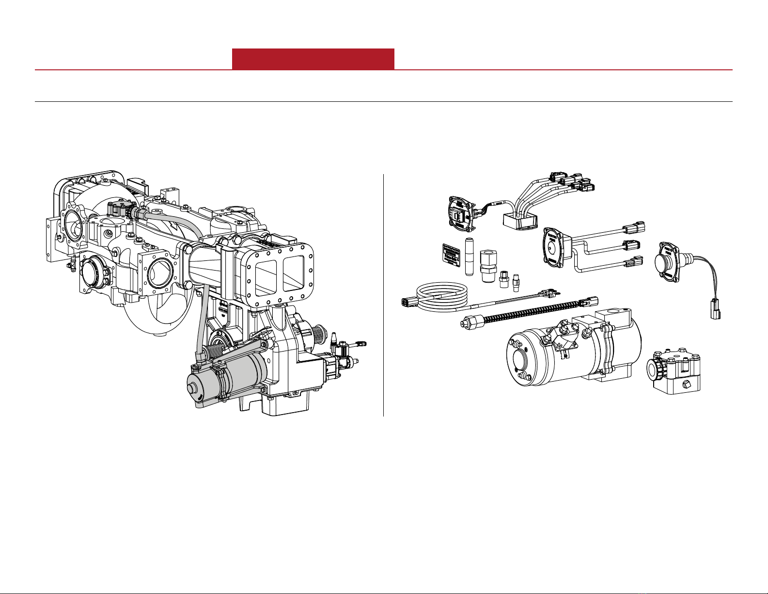
Product Overview 6
Congurations 6
Individually Installed Components 7
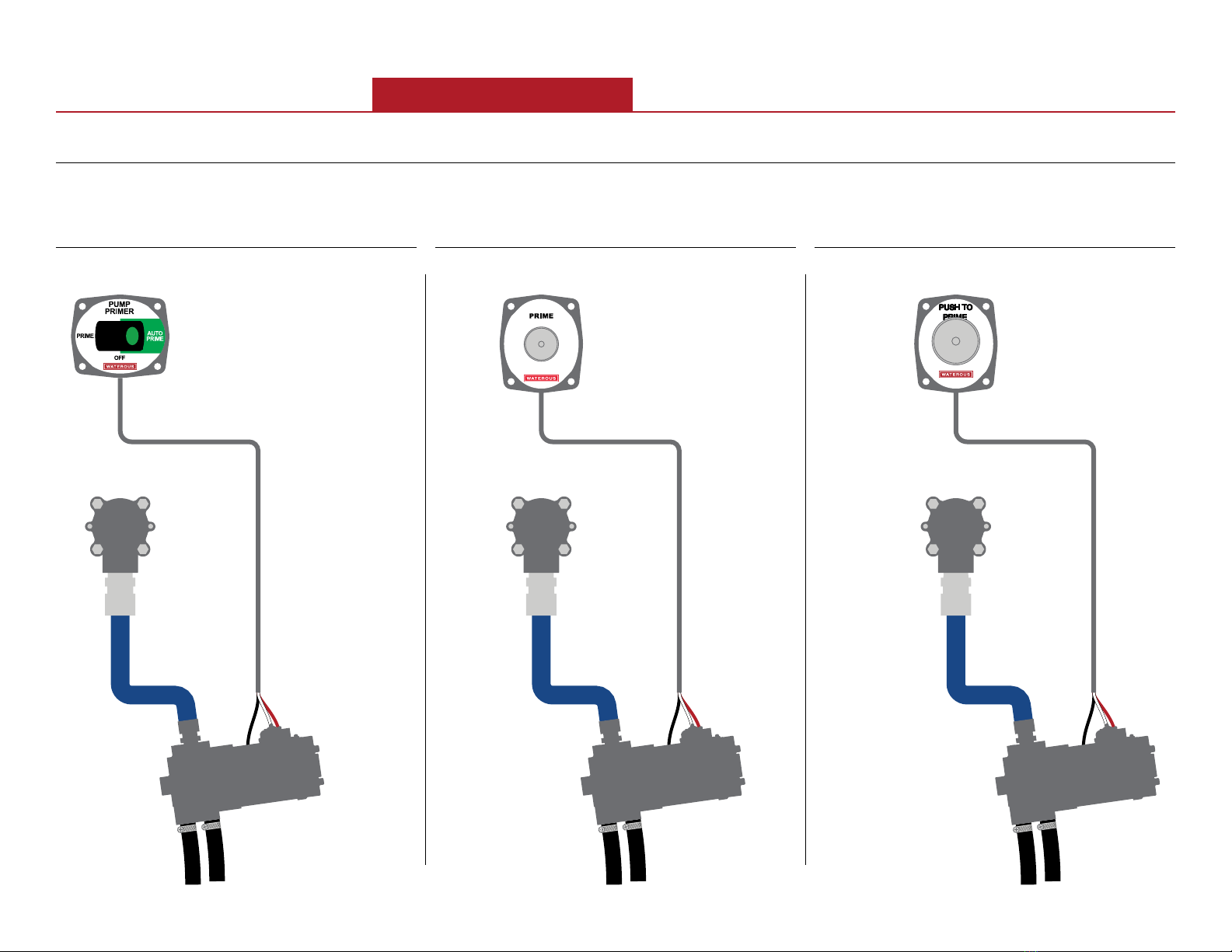
Panel Switch with Single Priming Pump
Overview 8
Auto-Prime Switch 8
Standard Push Button Switch 8
Oversized Push Button Switch 8
Multiple Priming Valve System Overview 9
Dual Priming Pump System Overview 10
Auto-Prime Switch 12
Standard Push Button Switch 14
Oversize Push Button Switch 15
Priming Pump—12V 16
Priming Pump—24V 17
Pressure Switch 18
Priming Valve Solenoid 19
Priming Valve 20
Priming Pump Cable 21
Priming Valve Solenoid Extension Cable 22
Extension Cable—Optional 23
Pressure Switch Extension Cable 24
Installation 25
Installation Overview 25
Determining Cable and Wire Routing 25
Preparing for the Installation 25
Optional Equipment 25
Hose and Tubing Requirements 25
Tubing 25
Hose 25
Determining the Installation Requirements 26
Installation Requirements 26
Auto-Prime Switch Cutout Dimensions 27
Standard Push Button Switch Dimensions 28
Oversized Push Button Switch Dimensions 29
Priming Pump Dimensions 30
Panel Cutout and Mounting Holes 31
Positioning the Switch 32
Mounting the Enclosure 33
Mounting the Panel 34
Installing the Standard Push Button Switch 35
Installing the Oversized Push Button Switch 36
Installing the Priming Pump 37
Installing the Priming Valve 38
Installing the Pressure Switch 39
Installing the Priming Valve Solenoid 40
Connecting to Apparatus Power 41
Priming Pump—12V 41
Priming Pump—24V 42
Dual Priming Pumps—12V 43
Dual Priming Pumps—24V 44
Connecting the Extension Cable 45
Priming Pump—12V 45
Priming Pump—24V 46
Dual Priming Pumps—12V 47
Dual Priming Pumps—24V 48
Connecting the Priming Components 49
Priming Pump and Priming Valve 49
Multiple Priming Valves 50
Dual Priming Pumps 51
Auto-Prime Push Button Switch 52
Standard Push Button Switch 53
Oversized Push Button Switch 54
Multiple Priming Valves 55
Multiple Priming Pumps 56
Priming the Pump—Auto-Prime Switch 57
Operation 58
Priming the Pump—Manual-Prime Switch 58
Maintenance 59
Maintenance Schedule 59
Vacuum Testing 59
Priming Valve 59
Priming Tank 59
Priming Pump 59