Watkins-Johnson Company WJ-8711A User manual

INSTALLATION, OPERATION, AND
INTERMEDIATE LEVEL MAINTENANCE MANUAL
FOR THE
WJ-8711A DIGITAL HF RECEIVER
P/N 181126-001, Revision Q
Copyright Signia-IDT, Inc. 1995
All Rights Reserved
Signia-IDT, Inc.
700 Quince Orchard Road
Gaithersburg, Maryland 20878-1794
November 2002
Courtesy of http://BlackRadios.terryo.org

PROPRIETARY STATEMENT
This document and subject matter disclosed herein are proprietary items to
which Signia-IDT, Inc. retains the exclusive right of dissemination, reproduction,
manufacture and sale.
This document is provided to the individual or using organization for their use
alone in the direct support of the associated equipment unless permission for
further disclosure is expressly granted in writing.
WARRANTY
Seller warrants for a period of one year from the date of shipment, unless a
different period has been agreed upon and incorporated into the Contract, that
the products delivered or services rendered will conform to the specifications
and be free from defects in workmanship and materials. THE FOREGOING
WARRANTIES ARE EXCLUSIVE AND IN LIEU OF ALL OTHER
WARRANTIES OF MERCHANTABILITY, FITNESS FOR PURPOSE, OR
OTHER WARRANTIES OR GUARANTIES OF ANY KIND OR
DESCRIPTION, WHETHER STATUTORY, EXPRESS, OR IMPLIED. If the
goods delivered or services performed fail to conform to the warranty stated in
this clause, Seller will correct the nonconformity at its expense by such repair,
adjustment, modification, or replacement of the goods or services as Seller
deems expedient. THE FOREGOING REMEDY OF BUYER FOR ANY
FAILURE OF THE GOODS OR SERVICES TO MEET ANY WARRANTY IS
EXCLUSIVE. BUYER EXPRESSLY AGREES THAT THE LIABILITY OF
SELLER UNDER ANY WARRANTY SHALL NOT INCLUDE DAMAGE TO
OUR LOSS OF PROPERTY OTHER THAN THE GOODS COVERED BY
THE CONTRACT; LOSS OF PROFITS OR REVENUE; INCREASED COSTS
OF ANY KIND; CLAIMS OF CUSTOMERS OF BUYER; OR ANY
INDIRECT, SPECIAL, INCIDENTAL, OR CONSEQUENTIAL DAMAGES.
As to goods or components where the customer has funded the repair, Seller will
warrant as limited above, the repaired portion of the unit for three months from
the date of reshipment. EQUIPMENT OR PARTS DESCRIBED AS BEING
MANUFACTURED BY OTHERS ARE SOLD BY SELLER AS IS and Buyer
must look to the respective manufacturer for any and all claims with regard to
said equipment or parts.
Courtesy of http://BlackRadios.terryo.org

iii
WARNING
This unit contains a RAM Integrated Circuit (A2U5) that includes an on-board
lithium source used as back up power for memory retention. Extreme care
should be used in storage, handling, and disposal of parts having lithium content.
Improper handling may present explosion hazard. If the Digital Assembly is to
be disposed, remove the RAM IC. If replacement of the IC is required, carefully
insert a blunt, nonmetallic, tool between the bottom face of the IC and the related
socket. Pry the IC up at a slight angle and remove with fingers.
•Wear eye protection when handling component with lithium content.
•Do not puncture, compact, incinerate, short circuit, or expose the lithium
energy source to temperatures above 176°F (80°C).
•Do not store ICs with lithium content loose in bins. Store `riginal
containers.
•Dispose of ICs with lithium content properly. Discharged cells should
be handled with care, as they retain significant energy. They should be
electrically isolated and packaged for disposal. Dispose in accordance
with local regulations for hazardous material disposal. DO NOT
INCINERATE OR COMPACT.
•Refer to Figure 7-23 for location of RAM IC (A2U5) on the Digital
Assembly (A2).
Courtesy of http://BlackRadios.terryo.org

iv
THIS PAGE INTENTIONALLY LEFT BLANK
Courtesy of http://BlackRadios.terryo.org

LIST OF EFFECTIVE PAGES WJ-8711A DIGITAL HF RECEIVER
v
LIST OF EFFECTIVE PAGES
Page Number Description Revision
iCover Q
ii Proprietary Statement Q
iii Warnings P
iv Intentionally Blank P
v List of Effective Pages Q
vi List of Effective Pages Q
vii Revision Record Q
viii Declaration of Conformity J
ix thru xv Table of Contents N
xvi Table of Contents N
1-iSection Cover J
1-0 Illustration J
1-1 Section One N
1-3 thru 1-4 Section One I
1-5 Section One P
1-6 thru 1-11 Section One L
1-12 Notes I
2-iSection Cover J
2-0 Illustration J
2-1 Section Two Q
2-3 thru 2-4 Section Two N
2-5 thru 2-6 Section Two K
2-7 Section Two P
2-8 thru 2-9 Section Two N
2-10 Section Two Q
2-11 Section Two P
2-12 Section Two Q
3-iSection Cover J
3-ii Intentionally Blank J
3-1 thru 3-44 Section ThreeN
4-iSection Cover J
4-ii Intentionally Blank J
4-1 thru 4-4 Section Four I
4-5 Section Four L
4-6 thru 4-8 Section Four I
4-9 Section Four L
4-10 Section Four I
4-11 thru 4-12 Section Four L
4-13 thru 4-14 Section Four I
4-15 Section Four L
4-16 Section Four I
4-17 Section Four L
4-18 thru 4-28 Section Four I
5-iSection Cover J
5-ii Intentionally Blank J
5-1 Section Five Q
5-2 thru 5-18 Section Five I
Courtesy of http://BlackRadios.terryo.org
WJ-8711A DIGITAL HF RECEIVER LIST OF EFFECTIVE PAGES
vi
LIST OF EFFECTIVE PAGES (Continued)
Page Number Description Revision
6-iSection Cover J
6-0 Illustration J
6-1 Section Six I
6-2 Section Six N
6-3 thru 6-5 Section Six I
6-6 Section Six N
6-7 thru 6-9 Section Six I
6-10 Section Six N
7-iSection Cover J
7-ii Intentionally Blank J
7-1 thru 7-10 Section Seven I
7-11 Section Seven P
7-12 thru 7-17 Section Seven K
7-18 Section Seven Q
7-19 thru 7-30 Section Seven K
8-iSection Cover J
8-ii Intentionally Blank J
8-1 thru 8-4 Section Eight Q
8-5 thru 8-6 Section Eight P
8-7 thru 8-9 Section Eight I
8-10 Section Eight P
8-11 thru 8-14 Section Eight I
8-15 Section Eight P
8-16 thru 8-28 Section Eight I
8-29 Section Eight P
8-30 thru 8-50 Section Eight I
FP-iSection Cover N
FP-ii Intentionally Blank N
FP-1/(FP-2 blank) Foldouts Q
FP-3/(FP-4 blank) Foldouts Q
FP-5/(FP-6 blank) Foldouts N
FP-7/(FP-8 blank) Foldouts N
FP-9/(FP-10 blank) Foldouts N
FP-11/(FP-12 blank) Foldouts N
FP-13/(FP-14 blank) Foldouts N
FP-15/(FP-16 blank) Foldouts N
FP-17/(FP-18 blank) Foldouts N
FP-19/(FP-20 blank) Foldouts N
FP-21/(FP-22 blank) Foldouts N
FP-23/(FP-24 blank) Foldouts N
FP-25/(FP-26 blank) Foldouts N
FP-27/(FP-28 blank) Foldouts N
FP-29/(FP-30 blank) Foldouts N
FP-31/(FP-32 blank) Foldouts N
FP-33/(FP-34 blank) Foldouts N
FP-35/(FP-36 blank) Foldouts N
FP-37/(FP-38 blank) Foldouts N
Courtesy of http://BlackRadios.terryo.org
WJ-8711A DIGITAL HF RECEIVER REVISION RECORD
vii
WJ-8711A DIGITAL HF RECEIVER
REVISION RECORD
Revision Description Date
AInitial issue. 11/93
BRevised specification related to IF bandwidth shape factors. 12/93
CProvides additional information in Section I concerning COR,
DSO1, 488, 8KRF, and PCSM options. Updates software release
history. Adds Appendix C for WJ-8711A/COR option and
Appendix G for WJ-8711/PCSM option.
2/94
DAdds Appendix H for WJ-871Y/485 option. Updates Appendix G
for WJ-871Y/PCSM option.
2/94
EProvides application information for the Mute Input terminal (TB1
terminal 12).
6/94
FProvides information on enhancements to the AGC software and on
the Synchronous AM (SAM) Detection Mode. Documents updated
Digital Assembly (A2).
3/95
GUpdated manual to reflect 871Y Control Version 04.01.05. Added
information about use of CI-V Level Converter when using CSMA
Interface.
11/95
HAdded information requiring the use of a shielded twisted pair
cable with the CSMA interface to ensure electromagnetic
compatibility with other devices. Added Declaration of
Conformity to IEC EMC standards. Also corrected errata. Bit 6 of
the Event Summary Status Register is not used. It cannot be set to
flag front panel parameter changes. Improved AGC attack time
specification from 15 ms to 5 msec.
04/96
IEliminated specifications related to environmental test methods
and vibration. Eliminated WJ-871Y/PCSM2 Personal Computer
Signal Monitor Option from list of available options. Added WJ-
871Y/PCSW freeware program to the equipment supplied list.
7/96
JAdded WJ part number to the title page. Incorporated a List of
Effective Pages. Added page numbers to section cover pages and
their back pages. Removed "intentionally left blank" pages and
replaced with "Notes" pages that are formatted with headers and
page numbers.
9/97
KIncorporated ECO 039216. 11/98
LIncorporated ECO 039120. 5/99
MIncorporated ECO 039595. 5/99
NIncorporated ECO 039674. 6/99
PIncorporated ECO 039883. 4/00
QIncorporated ECO 042507. 11/02
Courtesy of http://BlackRadios.terryo.org
viii
DECLARATION OF CONFORMITY
According to ISO/IEC Guide 22 and EN 45014
MANUFACTURER’S NAME:
WATKINS-JOHNSON COMPANY
Electronic Equipment Division
MANUFACTURER’S ADDRESS: 700 QUINCE ORCHARD ROAD
GAITHERSBURG, MARYLAND 20878-1794
U.S.A.
DECLARES THAT THE PRODUCT
PRODUCT NAME:
Digital HF Receiver
MODEL NUMBER: WJ-8711A
CONFORMS TO THE FOLLOWING SPECIFICATIONS AND/OR DIRECTIVES:
SAFETY:
IEC 1010-1: 1990 and EN61010-1: 1993 w/Amendment A2:
7/95
EMC:
EN50081-1 (Radiated and Conducted Emissions to EN55022,
Class B)
EN50082-1 (Including IEC 801-2: 1984, IEC 801-3: 1984 and
IEC 801-4: 1988)
EN55020 (Immunity for Receivers)
SUPPLEMENTARY INFORMATION:
Directives Compliance: Low Voltage (Safety) 73/23/EEC
EMC 89/336/EEC
AUTHORIZED SIGNATURE
BARRY N. WRIGHT
MANAGER, PRODUCT ASSURANCE
AND REGULATORY COMPLIANCE
LOCATION AND DATE OF DECLARATION:
Gaithersburg, Maryland, USA -November 12th, 1996
WATKINS-JOHNSON COMPANY
Courtesy of http://BlackRadios.terryo.org
WJ-8711A DIGITAL HF RECEIVER TABLE OF CONTENTS
ix
TABLE OF CONTENTS
WJ-8711A DIGITAL HF RECEIVER
SECTION I
GENERAL DESCRIPTION
Paragraph Page
1.1 Electrical Characteristics.......................................................................................... 1-1
1.2 Mechanical Characteristics ...................................................................................... 1-6
1.3 Equipment Supplied ................................................................................................. 1-7
1.4 Equipment Required But Not Supplied.................................................................... 1-7
1.5 Receiver Options ...................................................................................................... 1-7
1.5.1 WJ-871Y/REF Reference Generator Option............................................................ 1-7
1.5.2 WJ-8711/PRE Suboctave Preselector Option .......................................................... 1-7
1.5.3 WJ-8711A/COR Carrier-Operated Relay Option .................................................... 1-7
1.5.4 WJ-8711/DSO1 Digital Signal Output Option......................................................... 1-8
1.5.5 WJ-871Y/488 IEEE-488 Interface Option ............................................................... 1-8
1.5.6 WJ-871Y/8KRF 8 kHz Roofing Filter Option......................................................... 1-8
1.5.7 WJ-8711/SPK Internal Speaker Option ................................................................... 1-8
1.5.8 WJ-8711/BFP Blank Front Panel Option................................................................. 1-8
1.5.9 WJ-871Y/485 485 Interface Option......................................................................... 1-9
1.5.10 WJ-871Y/SEU Speech Enhancement Union ........................................................... 1-9
1.5.11 WJ-871Y/IFC 12.5 kHz IF Output Option............................................................... 1-9
1.5.12 WJ-871Y/FSK Frequency Shift Keying Option ...................................................... 1-9
1.6 WJ-8711 Software Version Release History............................................................ 1-9
1.6.1 WJ-8711A Internal Control Software Release History............................................ 1-9
1.6.2 WJ-8711A Front Panel Control Software Release History...................................... 1-10
1.6.3 WJ-8711A DSP Software Release History .............................................................. 1-11
SECTION II
INSTALLATION
Paragraph Page
2.1 Unpacking and Inspection ........................................................................................ 2-1
2.2 Installation................................................................................................................ 2-1
2.2.1 Rack Mounting......................................................................................................... 2-1
2.2.2 Mounting Feed for Table Top Operation................................................................. 2-3
2.2.3 Power Requirements ................................................................................................ 2-4
2.2.4 Connector Signals .................................................................................................... 2-4
2.2.4.1 RF IN, Antenna Input (A3J1)................................................................................... 2-5
2.2.4.2 SMO, Signal Monitor Output (A3J2)....................................................................... 2-6
2.2.4.3 EXT REF, External Reference Input (A3J3) ........................................................... 2-6
2.2.4.4 IF OUT, Post-Filtered IF Output (A2J1).................................................................. 2-6
2.2.4.5 CSMA, Carrier Sense/Multiple Access Port (A2J2)................................................ 2-6
Courtesy of http://BlackRadios.terryo.org
TABLE OF CONTENTS WJ-8711A DIGITAL HF RECEIVER
x
TABLE OF CONTENTS (Continued)
SECTION II (Continued)
Paragraph Page
2.2.4.6 A2J3, RS-232C Serial Interface Port ....................................................................... 2-6
2.2.4.7 TB1, Audio Terminal Block (TB1).......................................................................... 2-6
2.2.4.7.1 Line Audio Outputs (TB1 Terminals 1 thru 6) ........................................................ 2-6
2.2.4.7.2 Speaker Output (TB1 Terminals 7 and 8) ................................................................ 2-7
2.2.4.7.3 DC-Coupled Audio Output (TB1 Terminal 9)......................................................... 2-7
2.2.4.7.4 Remote Signal Strength Indicator Output (TB1 Terminal 10)................................. 2-7
2.2.4.7.5 Squelch Output (TB1 Terminal 11) ......................................................................... 2-7
2.2.4.7.6 Mute Input (TB1 Terminal 12)................................................................................. 2-7
2.2.4.8 POWER, 90-264 VAC Line Power Input (FL1J1) .................................................. 2-7
2.2.4.9 PHONES, Front Panel Headphones Jack (A1J1)..................................................... 2-7
2.2.4.10 Ground Stud ............................................................................................................. 2-8
2.2.5 Configuring the Receiver for Remote Operations.................................................... 2-8
2.3 Equipment Malfunctions.......................................................................................... 2-10
2.4 Preparation for Reshipment or Storage .................................................................... 2-11
SECTION III
LOCAL OPERATION
Paragraph Page
3.1 Introduction .............................................................................................................. 3-1
3.2 Description of Controls, Indicators, and Displays ................................................... 3-1
3.2.1 The Tuned Frequency Display ................................................................................. 3-2
3.2.2 The Tune Lock Key and Led.................................................................................... 3-2
3.2.3 The ←(Left) and →(Right) Arrow Keys ............................................................... 3-3
3.2.4 The Tuning Wheel.................................................................................................... 3-3
3.2.5 The ↑(Up) and ↓(Down) Arrow Keys ................................................................... 3-4
3.2.6 The Numeric Entry Keys (0-9 and Decimal Point).................................................. 3-5
3.2.7 The kHz (Kilohertz) and MHz (Megahertz) Keys ................................................... 3-6
3.2.8 The CE (Clear Entry) Key........................................................................................ 3-6
3.2.9 The Step Tune Key................................................................................................... 3-7
3.2.10 The Auxiliary Parameter Displays ........................................................................... 3-7
3.2.11 The IF BW Key and Led .......................................................................................... 3-7
3.2.12 The DET Mode Key and Led................................................................................... 3-8
3.2.13 The Squelch Key and Led ........................................................................................ 3-8
3.2.14 The AGC Key and Led............................................................................................. 3-9
3.2.15 The BFO Key and Led ............................................................................................. 3-9
3.2.16 The +/-Zero Key...................................................................................................... 3-9
3.2.17 The Blanker Key and Led ........................................................................................ 3-10
Courtesy of http://BlackRadios.terryo.org
WJ-8711A DIGITAL HF RECEIVER TABLE OF CONTENTS
xi
TABLE OF CONTENTS (Continued)
SECTION III (Continued)
LOCAL OPERATION
Paragraph Page
3.2.18 The Special Function Key and Led.......................................................................... 3-10
3.2.18.1 Selecting the Passband Tuning Mode with the SPECIAL FUNCTION Key .......... 3-11
3.2.18.2 Selecting the BITE Initialization Mode with the SPECIAL FUNCTION Key........ 3-12
3.2.18.3 Selecting the Remote Control Selection Mode
with the SPECIAL FUNCTION Key ....................................................................... 3-12
3.2.18.4 Selecting the Remote Baud Rate Entry Mode
with the SPECIAL FUNCTION Key ....................................................................... 3-12
3.2.18.5 Selecting the CSMA Address Mode with the SPECIAL FUNCTION Key ............ 3-13
3.2.18.6 Selecting the IF Bandwidth Select Mode
with the SPECIAL Function Key............................................................................. 3-13
3.2.18.7 Displaying the Currently Selected Reference Frequency ........................................ 3-13
3.2.18.8 Selecting the AGC Threshold Feature ..................................................................... 3-14
3.2.19 The Auxiliary Parameter Edit Knob ........................................................................ 3-15
3.2.20 The Memory/Scan Section Alphanumeric Display.................................................. 3-16
3.2.21 The Dwell Key and Led ........................................................................................... 3-16
3.2.22 The Step Size Key and Led ...................................................................................... 3-17
3.2.23 The Channel View key and Led............................................................................... 3-17
3.2.24 The Channel Execute Key and Led.......................................................................... 3-18
3.2.25 The Scan Type Key and Leds .................................................................................. 3-18
3.2.26 The Scan Setup Key and Led ................................................................................... 3-18
3.2.27 The Frequency Lockout Key.................................................................................... 3-20
3.2.28 The Channel Store Key ............................................................................................ 3-21
3.2.29 The Clear Key .......................................................................................................... 3-21
3.2.30 The Channel Include Key......................................................................................... 3-22
3.2.31 The Channel Skip Key ............................................................................................. 3-22
3.2.32 The Scan Key and Led ............................................................................................. 3-22
3.2.33 The Pause Key and Led............................................................................................ 3-23
3.2.34 The Memory/Scan Parameters Edit Knob................................................................ 3-23
3.2.35 The Phones Output Volume Control Knob.............................................................. 3-24
3.2.26 The Speaker Key and Leds....................................................................................... 3-24
3.2.37 The Speaker Output Volume Control Knob............................................................. 3-24
3.2.38 The RF Input Key..................................................................................................... 3-25
3.2.39 The Manual Gain Control Knob .............................................................................. 3-25
3.2.40 The Signal Level Meter............................................................................................ 3-25
3.2.41 The Remote Key and Led......................................................................................... 3-25
3.2.42 The Power Switch .................................................................................................... 3-26
3.3 Turning on the Receiver........................................................................................... 3-26
3.3.1 Performing a Cold Start at Power-Up ...................................................................... 3-26
3.4 Introduction Into Receiver Operations..................................................................... 3-27
3.5 Operation in the Manual Mode ................................................................................ 3-27
3.5.1 Entering the Tuned Frequency ................................................................................. 3-28
Courtesy of http://BlackRadios.terryo.org

TABLE OF CONTENTS WJ-8711A DIGITAL HF RECEIVER
xii
TABLE OF CONTENTS (Continued)
SECTION III (Continued)
LOCAL OPERATION
Paragraph Page
3.5.2 Selecting a Detection Mode ..................................................................................... 3-29
3.5.3 Selecting an IF Bandwidth ....................................................................................... 3-30
3.5.3.1 Including an IF Bandwidth Filter for Selection ....................................................... 3-31
3.5.4 Setting the Squelch Level......................................................................................... 3-31
3.5.5 Attenuating or Amplifying Input Signals Via the RF Input Path Selection............. 3-32
3.5.6 Selecting the Gain Control Mode............................................................................. 3-32
3.5.7 Aiding CW Detection with the BFO Function......................................................... 3-32
3.5.8 Passband Tuning in CW Detection Mode................................................................ 3-33
3.5.9 Blanking Out Noise Interference.............................................................................. 3-34
3.5.10 Using the Tunable Notch Filter................................................................................ 3-34
3.6 Storing Current Receiver Parameters in Memory .................................................... 3-36
3.7 Changing Receiver Parameters to Those Stored in a Memory Channel .................. 3-36
3.8 Operation in the Scan Mode..................................................................................... 3-36
3.8.1 Using the Dwell Timer............................................................................................. 3-37
3.8.2 Scan Setups .............................................................................................................. 3-37
3.8.2.1 CHANNEL Scan Setup ............................................................................................ 3-38
3.8.2.2 Frequency-to-Frequency (F1→F2) Scan Setup........................................................ 3-39
3.8.2.3 Frequency-to-Frequency with Lockouts (F1→F2 w/Lock) Scan Setup .................. 3-39
3.8.3 Placing the Receiver in Scan Mode.......................................................................... 3-40
3.8.4 Pausing and Restarting Scans................................................................................... 3-40
3.9 Running the Built-In-Test Function (BITE)............................................................. 3-41
3.10 Displaying the Receiver's Current Internal Control Software Version.................... 3-42
3.11 Setting Remote Operation Configurations from the Front Panel............................. 3-43
3.11.1 Selecting the RS-232 or the CSMA Interface for Remote Operations .................... 3-43
3.11.2 Selecting the Baud Rate for Remote Operations...................................................... 3-43
3.11.3 Selecting the Receiver's Address for CSMA Remote Operations............................ 3-43
SECTION IV
RS-232 REMOTE OPERATION
Paragraph Page
4.1 Introduction .............................................................................................................. 4-1
4.2 Interfacing With the WJ-8711A............................................................................... 4-2
4.3 Command Message Formatting................................................................................ 4-3
4.3.1 Terminators for Commands and Queries ................................................................. 4-3
4.3.2 Formats of Query Responses.................................................................................... 4-3
4.3.3 Representations of Numeric Arguments .................................................................. 4-3
Courtesy of http://BlackRadios.terryo.org
WJ-8711A DIGITAL HF RECEIVER TABLE OF CONTENTS
xiii
TABLE OF CONTENTS (Continued)
SECTION IV
RS-232 REMOTE OPERATION (Continued)
Paragraph Page
4.4 Receiver Device Messages....................................................................................... 4-4
4.5 Communication Messages........................................................................................ 4-16
4.6 Receiver Status Summary ........................................................................................ 4-20
4.6.1 Status Bytes .............................................................................................................. 4-23
4.6.2 Event Summary Status Register ............................................................................... 4-23
4.6.3 Receiver Status Register........................................................................................... 4-24
4.6.4 Device-Dependent Error Register ............................................................................ 4-25
4.7 Message Processing.................................................................................................. 4-26
4.8 RS-232 Communications Protocol........................................................................... 4-27
4.8.1 XON/XOFF Protocol ............................................................................................... 4-27
4.8.2 ENQ/ACK Protocol.................................................................................................. 4-28
4.8.3 Buffer Handling........................................................................................................ 4-28
4.8.3.1 Input Buffer .............................................................................................................. 4-28
4.8.3.2 Output Buffer ........................................................................................................... 4-28
SECTION V
CSMA REMOTE CONTROL
Paragraph Page
5.1 Introduction .............................................................................................................. 5-1
5.2 Controlling Multiple Receivers Via the CSMA Interface........................................ 5-1
5.3 Setting Up the Receiver For Remote CSMA Interface ............................................ 5-2
5.4 Electrical Requirements of the Interface.................................................................. 5-3
5.5 Serial Data Transmissions........................................................................................ 5-4
5.6 Command Message Formatting................................................................................ 5-4
5.7 Control Codes........................................................................................................... 5-5
5.8 Details on Command and Response Formats........................................................... 5-7
5.8.1 Tuned Frequency Command Without Acknowledge [00] ....................................... 5-7
5.8.2 Tuned Frequency Command With Acknowledge [05] ............................................ 5-8
5.8.3 Response To Tuned Frequency Requests [03]......................................................... 5-9
5.8.4 Response To Tuned Frequency Range Requests [02].............................................. 5-9
5.8.5 Detection Mode/IF Bandwidth Command Without Acknowledge [01] .................. 5-10
5.8.6 Detection Mode/IF Bandwidth Command With Acknowledge [06] ....................... 5-11
5.8.7 Response To Detection Mode/IF Bandwidth Requests [04].................................... 5-11
5.8.8 Gain Control Mode Command With Acknowledge [31] ......................................... 5-12
Courtesy of http://BlackRadios.terryo.org
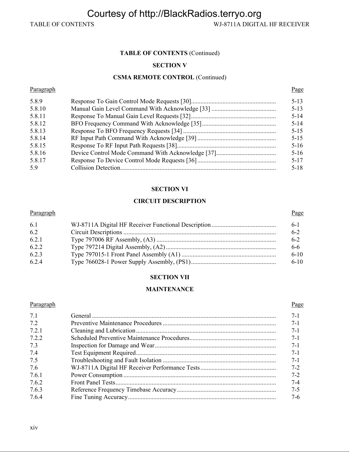
TABLE OF CONTENTS WJ-8711A DIGITAL HF RECEIVER
xiv
TABLE OF CONTENTS (Continued)
SECTION V
CSMA REMOTE CONTROL (Continued)
Paragraph Page
5.8.9 Response To Gain Control Mode Requests [30]...................................................... 5-13
5.8.10 Manual Gain Level Command With Acknowledge [33] ......................................... 5-13
5.8.11 Response To Manual Gain Level Requests [32]...................................................... 5-14
5.8.12 BFO Frequency Command With Acknowledge [35]............................................... 5-14
5.8.13 Response To BFO Frequency Requests [34] ........................................................... 5-15
5.8.14 RF Input Path Command With Acknowledge [39] .................................................. 5-15
5.8.15 Response To RF Input Path Requests [38]............................................................... 5-16
5.8.16 Device Control Mode Command With Acknowledge [37]...................................... 5-16
5.8.17 Response To Device Control Mode Requests [36] .................................................. 5-17
5.9 Collision Detection................................................................................................... 5-18
SECTION VI
CIRCUIT DESCRIPTION
Paragraph Page
6.1 WJ-8711A Digital HF Receiver Functional Description ......................................... 6-1
6.2 Circuit Descriptions ................................................................................................. 6-2
6.2.1 Type 797006 RF Assembly, (A3) ............................................................................ 6-2
6.2.2 Type 797214 Digital Assembly, (A2) ...................................................................... 6-6
6.2.3 Type 797015-1 Front Panel Assembly (A1) ............................................................ 6-10
6.2.4 Type 766028-1 Power Supply Assembly, (PS1)...................................................... 6-10
SECTION VII
MAINTENANCE
Paragraph Page
7.1 General ..................................................................................................................... 7-1
7.2 Preventive Maintenance Procedures ........................................................................ 7-1
7.2.1 Cleaning and Lubrication......................................................................................... 7-1
7.2.2 Scheduled Preventive Maintenance Procedures....................................................... 7-1
7.3 Inspection for Damage and Wear............................................................................. 7-1
7.4 Test Equipment Required......................................................................................... 7-1
7.5 Troubleshooting and Fault Isolation ........................................................................ 7-1
7.6 WJ-8711A Digital HF Receiver Performance Tests................................................ 7-2
7.6.1 Power Consumption ................................................................................................. 7-2
7.6.2 Front Panel Tests...................................................................................................... 7-4
7.6.3 Reference Frequency Timebase Accuracy............................................................... 7-5
7.6.4 Fine Tuning Accuracy.............................................................................................. 7-6
Courtesy of http://BlackRadios.terryo.org
WJ-8711A DIGITAL HF RECEIVER TABLE OF CONTENTS
xv
TABLE OF CONTENTS (Continued)
SECTION VII (Continued)
MAINTENANCE
Paragraph Page
7.6.5 Signal Strength Accuracy......................................................................................... 7-7
7.6.6 WJ-8711A Sensitivity Performance Test................................................................. 7-8
7.6.7 Audio Distortion Performance Test ......................................................................... 7-11
7.6.8 Squelch/Mute Performance Test .............................................................................. 7-13
7.6.9 Reconstructed IF Output Performance Test............................................................. 7-14
7.6.10 RF/IF Signal Path Performance Test........................................................................ 7-16
7.7 Corrective Maintenance Procedures ........................................................................ 7-18
7.7.1 Removing the Receiver Top Cover .......................................................................... 7-18
7.7.2 Replacing the Receiver Top Cover .......................................................................... 7-19
7.7.3 Front Panel Assembly (A1) Removal Procedures.................................................... 7-19
7.7.4 Front Panel Assembly (A1) Replacement Procedures ............................................. 7-19
7.7.5 Front Panel PC Assembly (A1A1) Removal Procedures......................................... 7-21
7.7.6 Front Panel PC Assembly (A1A1) Replacement Procedures .................................. 7-21
7.7.7 Digital Control PC Assembly (A2) Removal Procedures ........................................ 7-22
7.7.8 Digital Control PC Assembly (A2) Replacement Procedures ................................. 7-23
7.7.9 RF Tuner Assembly (A3) Removal Procedures....................................................... 7-24
7.7.10 RF Tuner Assembly (A3) Replacement Procedures ................................................ 7-24
7.7.11 Power Supply Assembly (PS1) Removal Procedures .............................................. 7-26
7.7.12 Power Supply Assembly (PS1) Replacement Procedures........................................ 7-27
7.7.13 Filter/Power (FL1J1) Removal Procedures.............................................................. 7-27
7.7.14 Filter/Power (FL1J1) Replacement Procedures ....................................................... 7-27
7.7.15 Ram/Battery (A2U5) Removal/Replacement Procedures........................................ 7-29
SECTION VIII
REPLACEMENT PARTS LIST
Paragraph Page
8.1 Unit Numbering Method .......................................................................................... 8-1
8.2 Reference Designation Prefix .................................................................................. 8-1
8.3 Provisioning Note –Inconsistencies In Part Numbering Conventions .................... 8-1
8.4 List of Manufacturers............................................................................................... 8-2
8.5 Parts List................................................................................................................... 8-2
8.6 WJ-8711A Digital HF Receiver, Main Chassis ....................................................... 8-5
8.6.1 Type 482108-1 Front Panel PC Assembly, A1A1 ................................................... 8-6
8.6.2 Type 797214-1 Digital Control PC Assembly, A2 .................................................. 8-10
8.6.3 Type 797006-1 RF Tuner PC Assembly, A3 ........................................................... 8-29
Courtesy of http://BlackRadios.terryo.org

TABLE OF CONTENTS WJ-8711A DIGITAL HF RECEIVER
xvi
TABLE OF CONTENTS (Continued)
FOLDOUTS
Foldout Page
FO-1 WJ-8711A Critical Dimensions Diagram ................................................................ FP-1
FO-2 Front Panel Controls, Indicators and Display .......................................................... FP-3
FO-3 Example of a Channel Scan Operation (3 Sheets) ................................................... FP-5
FO-4 Example of an F1 →F2 Scan Operation with and without Lockouts (2 Sheets) .... FP-11
FO-5 Type 797006-X RF Tuner Assembly (A3), Schematic
Diagram 581274 (3 Sheets)...................................................................................... FP-15
FO-6 Type 797214-1 Digital Control Assembly (A2), Schematic
Diagram 581839 (4 Sheets)...................................................................................... FP-21
FO-7 Type 482108-1 Front Panel Circuit Card Assembly (A2A1),
Schematic Diagram 581267 (2 Sheets) .................................................................... FP-29
FO-8 Type WJ-8711A Digital HF Receiver, Main Chassis
Schematic 581650 (3 Sheets) ................................................................................... FP-33
LIST OF TABLES
Table Page
1-1 WJ-8711A Digital HF Receiver Specifications ....................................................... 1-2
2-1 List of Connectors .................................................................................................... 2-5
3-1 Tunable Notch Filter Range ..................................................................................... 3-35
3-2 BITE Error Codes..................................................................................................... 3-41
4-1 Receiver Device Messages....................................................................................... 4-5
4-2 Communication Messages........................................................................................ 4-16
4-3 Status Byte Register, Bit Evaluation........................................................................ 4-20
4-4 Event Summary Status Register, Bit Evaluation...................................................... 4-24
4-5 Receiver Status Register, Bit Evaluation ................................................................. 4-25
4-6 Device-Dependent Error Register, Bit Evaluation................................................... 4-26
4-7 Supported RS-232C Communications Control Commands ..................................... 4-27
5-1 CSMA Control Code................................................................................................ 5-6
6-1 RF Data Control ....................................................................................................... 6-6
7-1 Required Test Equipment......................................................................................... 7-2
7-2 Receiver Sensitivity Performance Test Equipment Connection .............................. 7-9
7-3 Selected IF Bandwidth Frequency Range ................................................................ 7-16
Courtesy of http://BlackRadios.terryo.org

WJ-8711A DIGITAL HF RECEIVER TABLE OF CONTENTS
xvii
TABLE OF CONTENTS (Continued)
LIST OF ILLUSTRATIONS
Figure Page
1-1 WJ-8711A HF Receiver ........................................................................................... 1-0
2-1 Installation of Jonathan Type 110QD-16-2 Slide Mounts ....................................... 2-2
2-2 Installing the Mounting Feet for Table Top Operation............................................ 2-3
2-3 WJ-8711A Rear Panel.............................................................................................. 2-4
2-4 Locating and Setting Configuration DIP Switches A2S1 and A2S2 ....................... 2-9
2-5 Examples of Set DIP Switches A2S1 and A2S2...................................................... 2-10
4-1 Receiver Status Data Structure................................................................................. 4-20
5-1 Recommended Controller Setup .............................................................................. 5-2
5-2 Composition of One Byte of Serial Data ................................................................. 5-4
5-3 Format of Typical Command Message Packet......................................................... 5-4
5-4 Format of ACK and NAK Messages........................................................................ 5-5
5-5 Tuned Frequency Command Format Without Acknowledge .................................. 5-8
5-6 Tuned Frequency Command Format With Acknowledge........................................ 5-8
5-7 Tuned Frequency Request Response Format........................................................... 5-9
5-8 Tuned Frequency Range Request Response Format................................................ 5-10
5-9 Detection Mode/IF Bandwidth Command Format Without Acknowledge ............. 5-10
5-10 Detection Mode/IF Bandwidth Command Format With Acknowledge................... 5-11
5-11 Detection Mode/IF Bandwidth Request Response Format...................................... 5-12
5-12 Gain Control Mode Command Format .................................................................... 5-12
5-13 Gain Control Mode Request Format ........................................................................ 5-13
5-14 Manual Gain Level Command Format..................................................................... 5-13
5-15 Manual Gain Level Request Format ........................................................................ 5-14
5-16 BFO Frequency Command Format .......................................................................... 5-14
5-17 BFO Frequency Request Response Format.............................................................. 5-15
5-18 RF Input Path Command Format ............................................................................. 5-16
5-19 RF Input Path Request Response Format................................................................. 5-16
5-20 Device Control Mode Command Format................................................................. 5-17
5-21 Device Control Mode Request Response Format .................................................... 5-17
5-22 Jammer Code............................................................................................................ 5-18
6-1 Digital HF Receiver Functional Block Diagram...................................................... 6-0
6-2 Type 797006-1 RF Assembly Block Diagram ......................................................... 6-3
6-3 Type 797214-1 Digital Assembly Functional Block Diagram................................. 6-7
6-4 Type 797015-1 Front Panel Assembly Functional Block Diagram ......................... 6-11
7-1 Power Consumption Performance Test Equipment Connection.............................. 7-3
7-2 Front Panel Test Equipment Connections................................................................ 7-4
7-3 Reference Frequency Timebase Accuracy
Performance Test Equipment Connection................................................................ 7-5
7-4 Fine Tuning Accuracy Performance Test Equipment Connection........................... 7-6
7-5 Receiver Sensitivity Performance Test Equipment Connection .............................. 7-8
7-6 Audio Distortion Performance Test Equipment Connection ................................... 7-11
7-7 Squelch/Mute Performance Test Equipment Connection ........................................ 7-13
Courtesy of http://BlackRadios.terryo.org
TABLE OF CONTENTS WJ-8711A DIGITAL HF RECEIVER
xviii
TABLE OF CONTENTS (Continued)
LIST OF ILLUSTRATIONS
Figure Page
7-8 Reconstructed IF Output Performance Test Equipment Connection....................... 7-14
7-9 RF/IF Signal Path Performance Test Equipment Connection.................................. 7-16
7-10 Removing/Replacing Receiver Top Cover............................................................... 7-18
7-11 Front Panel Assembly (A1) Remove and Replace Procedures (Part 1)................... 7-20
7-12 Front Panel Assembly (A1) Remove and Replace Procedures (Part 2)................... 7-20
7-13 Front Panel PC Assembly (A1A1) Remove and Replace Procedures (Part 1) ........ 7-21
7-14 Front Panel PC Assembly (A1A1) Remove and Replace Procedures (Part 2) ........ 7-22
7-15 Digital Control PC Assembly (A2) Remove and Replace Procedures (Part 1) ....... 7-23
7-16 Digital Control PC Assembly (A2) Remove and Replace Procedures (Part 2) ....... 7-24
7-17 RF Tuner Assembly (A3) Remove and Replace Procedures (Part 1) ...................... 7-25
7-18 RF Tuner Assembly (A3) Remove and Replace Procedures (Part 2) ...................... 7-25
7-19 Power Supply (PS1) Remove and Replace Procedures (Part 1) .............................. 7-26
7-20 Power Supply (PS1) Remove and Replace Procedures (Part 2) .............................. 7-27
7-21 Filter/Power (FL1J1) Removal and Replacement Procedures (Part 1).................... 7-28
7-22 Filter/Power (FL1J1) Removal and Replacement Procedures (Part 2).................... 7-28
7-23 RAM/BATTERY (U5) Removal and Replacement Procedures.............................. 7-30
8-1 WJ-8711A Main Chassis Component Locations ..................................................... 8-4
LIST OF APPENDICES
Appendix A Type WJ-871Y/REF Reference Generator Option (P/N 181280-001)
Appendix B Type WJ-8711/PRE Suboctave Preselector Option (P/N 181281-001)
Appendix C WJ-8711A/COR Carrier-Operated Relay Option (P/N 181282-001)
Appendix D Type WJ-8710/DS01, WJ-8711/DS01, and WJ-8712/DS01 Digital Signal
Output Options (P/N 181272-001)
Appendix E WJ-8711/488 and WJ-8712/488 IEEE-488 Interface Options (P/N 181283-001)
Appendix F WJ-871Y/8KRF 8 kHz Roofing Filter Option (P/N 181284-001)
Appendix G Future Use
Appendix H WJ-871Y/485 RS-485 Interface Option (P/N 181273-001)
Appendix I Type WJ-871Y/SEU Speech Enhancement Unit (P/N 181274-001)
Appendix J WJ-871Y/IFC125 12.5 kHz IF Output Option (P/N 181275-001)
Appendix K Type WJ-871Y/FSK Frequency Shift Keying Option (P/N 181401-001)
Courtesy of http://BlackRadios.terryo.org

1-i
SECTION I
GENERAL DESCRIPTION
Courtesy of http://BlackRadios.terryo.org
GENERAL DESCRIPTION WJ-8711A DIGITAL HF RECEIVER
1-0
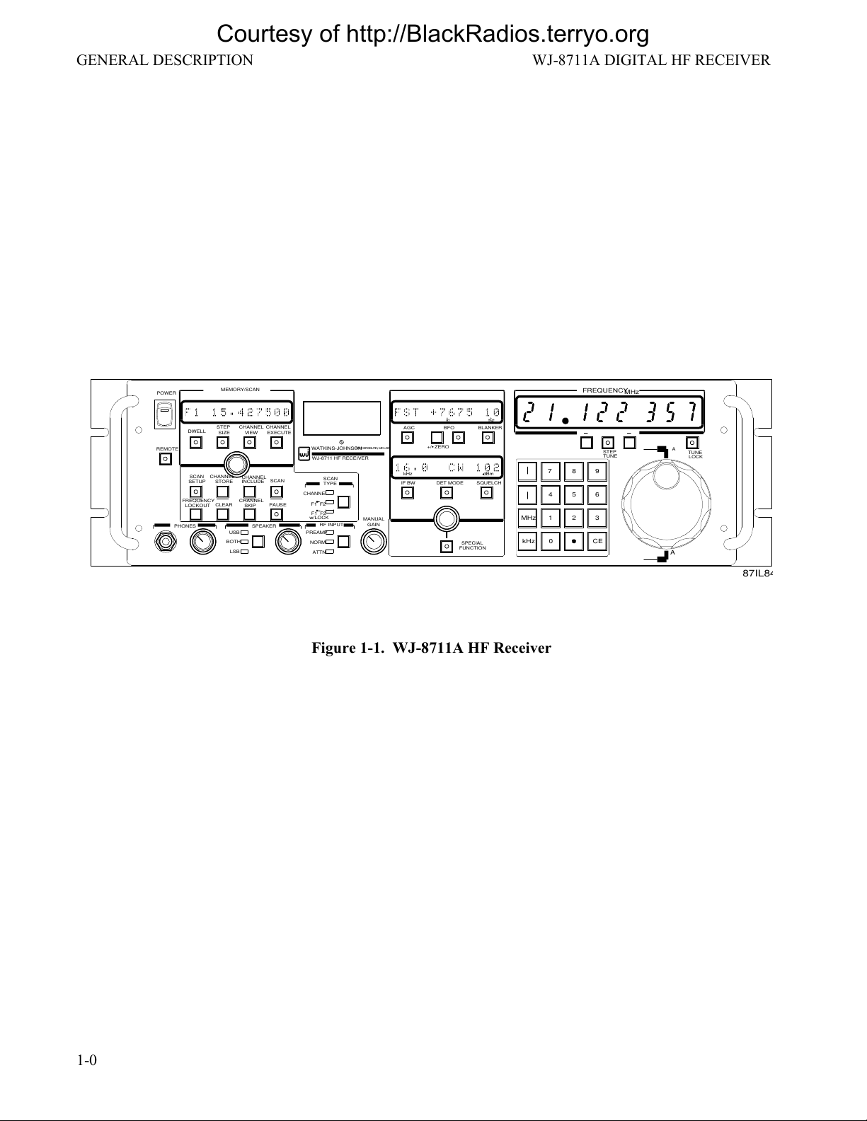
87IL84
A
A
MEMORY/SCAN
MHz
FREQUENCY
SCAN
EXECUTE
CHANNEL
VIEW
CHANNEL
SIZE
STEP
DWELL
SKIPLOCKOUT
INCLUDESTORE
SETUP SCAN
PAUSE
CHANNEL
CHANNEL
CHANNEL
CLEAR
FREQUENCY
TUNE
STEP
LOCK
MANUAL
REMOTE
FUNCTION
SPECIAL
+/- ZERO
TYPE
SCAN
F1 F2
CHANNEL
F1 F2
w/LOCK
TUNE
kHz
WJ-8711 HF RECEIVER
MHz
7
0
POWER
WATKINS-JOHNSON
CE
ATTN
NORM
PREAMP
LSB
BOTH
USB
GAIN
SPEAKERPHONES
SQUELCHDET MODEIF BW
BLANKERBFOAGC
kHz dBm
mSec
Hz
RF INPUT
4
1
8
5
2
9
6
3
GAITHERSBURG,MDUSA
Figure 1-1. WJ-8711A HF Receiver
Courtesy of http://BlackRadios.terryo.org
Table of contents


