trig TY91 User manual

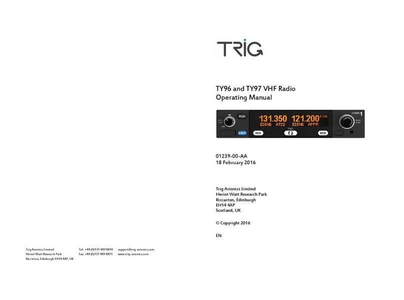
TY91/TY92 VHF radio
Installation Manual
00839-00-AF
24 November 2014
Trig Avionics Limited
Heriot Watt Research Park
Riccarton, Edinburgh
EH14 4AP
Scotland, UK
Copyright Trig Avionics Limited 2013, 2014

This page intentionally left blank

TY91/TY92 VHF Radio Installation Manual 24 November 2014
00839-00 Issue AF
______________________
Trig Avionics Limited i
CONTENTS
1. PREFACE...............................................................................................6
1.1 PURPOSE...........................................................................................6
1.2SCOPE...............................................................................................6
1.3 CHANGES FROM PREVIOUS ISSUE......................................................6
1.4 DOCUMENT CROSS-REFERENCES......................................................7
2. INTRODUCTION..................................................................................8
2.1 TY91/TY92 DESCRIPTION................................................................8
2.2 INTERFACES......................................................................................9
2.2.1 TY91/TY92 VHF radio Unit .....................................................9
2.2.2 TC90 Controller Unit...............................................................9
3. TECHNICAL SPECIFICATIONS.....................................................11
3.1 TY91 VHF RADIO UNIT (00882-00-01) .........................................11
3.2 TY92 VHF RADIO UNIT (00879-00-01) .........................................12
3.3 TC90 CONTROL UNIT (00857-00-01) .............................................14
3.4 LOW VOLTAGE OPERATION ............................................................14
3.5 INSTALLATION APPROVAL...............................................................15
4. UNIT AND ACCESSORIES SUPPLIED...........................................16
4.1 TY91 VHF RADIO ITEMS................................................................16
4.2 TY92 VHF RADIO ITEMS................................................................16
4.3 TC90 CONTROLLER ITEMS..............................................................16
4.4 TY91/TY92 INSTALLATION KIT .....................................................17
4.5 TC90 INSTALLATION KIT ................................................................17

TY91/TY92 VHF Radio Installation Manual 24 November 2014
00839-00 Issue AF
______________________
ii Trig Avionics Limited
4.6 REQUIRED ITEMS ............................................................................17
5. INSTALLATION.................................................................................19
5.1 UNPACKING AND INSPECTING EQUIPMENT......................................19
5.2 TC90 CONTROLLER MOUNTING......................................................19
5.2.1 Dual TC90 Considerations ....................................................20
5.3 VHF RADIO MAIN UNIT MOUNTING...............................................20
5.4 COOLING REQUIREMENTS ...............................................................21
5.5 TY91/TY92 VHF RADIO ELECTRICAL CONNECTIONS....................21
5.5.1 TY91/TY92 Interface –Pinout................................................21
5.6 TY91/TY92 VHF RADIO INTERFACE DETAILS...............................23
5.6.1 Speaker Output.......................................................................23
5.6.2 TMAP Bus..............................................................................23
5.6.3 Headphone Output.................................................................23
5.6.4 Controller Power ...................................................................23
5.6.5 Power On ...............................................................................24
5.6.6 PTT1/2 Key Input...................................................................24
5.6.7 Intercom Key Input.................................................................24
5.6.8 Transmit Interlock..................................................................24
5.6.9 Auxiliary Audio Input.............................................................25
5.6.10 Microphone Input...................................................................25
5.6.11 Power Input............................................................................26
5.6.12 Ground Returns......................................................................26
5.7 TC90 CONTROLLER ELECTRICAL CONNECTIONS ............................26
5.7.1 TC90 Interface - Pinout .........................................................26

TY91/TY92 VHF Radio Installation Manual 24 November 2014
00839-00 Issue AF
______________________
Trig Avionics Limited iii
5.8 TC90 CONTROLLER INTERFACE DETAILS .......................................27
5.8.1 TMAP Bus..............................................................................27
5.8.2 RS232 Input............................................................................28
5.8.3 Remote ON.............................................................................28
5.8.4 Power.....................................................................................28
5.8.5 Step Button.............................................................................28
5.8.6 Transfer Button ......................................................................29
5.9 DCONNECTOR CRIMP TERMINALS .................................................29
5.10 WIRING CONSIDERATIONS...............................................................30
5.10.1 TC90 Interconnect..................................................................30
5.10.2 Dual TC90 Interconnect.........................................................31
5.10.3 Audio wiring...........................................................................33
5.11 ANTENNA INSTALLATION................................................................33
5.11.1 Antenna Ground Plane...........................................................34
5.11.2 Antenna Cable........................................................................34
5.11.3 TNC Connector ......................................................................35
6. INSTALLATION SETUP AND TEST...............................................37
6.1 INITIAL POWER ON..........................................................................37
6.2 CONFIGURATION ITEMS...................................................................37
6.2.1 Intercom Volume....................................................................38
6.2.2 Intercom Squelch....................................................................38
6.2.3 Auxiliary Input Volume ..........................................................38
6.2.4 Auxiliary Input Muting...........................................................38
6.2.5 Sidetone Volume.....................................................................38

TY91/TY92 VHF Radio Installation Manual 24 November 2014
00839-00 Issue AF
______________________
iv Trig Avionics Limited
6.2.6 Radio Squelch Offset..............................................................39
6.2.7 Frequency Step Size ...............................................................39
6.2.8 Display Brightness .................................................................39
6.2.9 Microphone Sensitivity Adjustment........................................39
7. POST INSTALLATION CHECKS....................................................41
8. NORMAL OPERATION ....................................................................42
8.1 OVERVIEW......................................................................................42
8.2 DISPLAY..........................................................................................42
8.3 ON/OFF VOLUME KNOB..................................................................42
8.4 TUNING KNOBS...............................................................................43
8.5 FLIP-FLOP BUTTON..........................................................................43
8.6 MON BUTTON................................................................................43
8.7 MEM BUTTON................................................................................43
8.8 DUAL CONTROL OPERATION...........................................................44
8.9 DUAL CONTROL INDIVIDUAL FUNCTIONS........................................44
8.10 GENERAL LOW TEMPERATURE OPERATION....................................45
8.11 WARNING MESSAGES......................................................................45
8.12 FAULT ANNUNCIATION ...................................................................45
9. CONTINUED AIRWORTHINESS....................................................47
9.1 CLEANING THE TC90 CONTROLLER ................................................47
10. LIMITED WARRANTY.................................................................48
11. ENVIRONMENTAL QUALIFICATION FORMS ......................49
12. INSTALLATION DRAWINGS......................................................55

TY91/TY92 VHF Radio Installation Manual 24 November 2014
00839-00 Issue AF
______________________
Trig Avionics Limited v
12.1 MOUNTING TRAY FIXING AND OVERALL DIMENSIONS......................55
12.2 FRONT PANEL CONTROLLER DIMENSIONS ......................................56
12.3 FRONT PANEL CUT-OUT OPTIONS ...................................................57
13. WIRING DIAGRAMS.....................................................................59

TY91/TY92 VHF Radio Installation Manual 24 November 2014
00839-00 Issue AF
______________________
6 Trig Avionics Limited
1. Preface
1.1 Purpose
This manual describes the physical and electrical characteristics and the
installation requirements for a TY91/TY92 VHF radio and associated
controller.
1.2 Scope
This document applies to the installation of the TY91 and TY92 VHF radio.
This manual applies to TY91/TY92 software version 1.5 or later and TC90
controller software version 1.4 or later. The software versions and FPGA are
subject to change without notice.
1.3 Changes from Previous Issue
Changes from Issue AE to Issue AF are:
2.1
Additional description of a dual TC90 installation
2.2
TC90 interface table updated
Section 4
New part numbers and tables added
Section 5
Additional installation information included for dual TC90
installations
5.6.10
Statement added to address dynamic microphone
connections
Section 6
Additional installation information included for dual TC90
installations
Section 8
Dual TC90 operation information included
Section 11
Environmental tables updated to correct the lightning
induced transient susceptibility category from “B2H22” to
“B2H2L2”

TY91/TY92 VHF Radio Installation Manual 24 November 2014
00839-00 Issue AF
______________________
Trig Avionics Limited 7
Section 13
Additional wiring diagrams to include dual TC90
installation
Various
The phrase “receiver squelch” changed to “radio squelch”
to show consistency between installation and operation
manuals
1.4 Document Cross-References
00840-00
TY91 VHF radio Operating Manual
AD
ETSO 2C169a
VHF Radio communication receiving equipment
operating within the radio frequency range
117.875 –137 MHz
EASA
TSO C169a
Minimum Operational Performance standards for
Airborne Radio Communications equipment
standards
FAA
ETSO 2C128
Devices that prevent blocked channels used in
two-way radio communications due to
unintentional transmissions
EASA
TSO C128a
Equipment that prevents blocked channels used in
two-way radio communications due to
unintentional transmissions
FAA

TY91/TY92 VHF Radio Installation Manual 24 November 2014
00839-00 Issue AF
______________________
8 Trig Avionics Limited
2. Introduction
2.1 TY91/TY92 Description
The TY91/TY92 VHF radio system is an ED-23C compliant class C (25 kHz
offset carrier) and class E (8.33 kHz single carrier) VHF radio. The TY91 has
a nominal power output of 6 watts, and meets the power output requirements
for Class 4 and Class 6. The TY92 has a nominal power output of 16 watts,
and meets the power output requirements for Class 3 and Class 5. The
TY91/TY92 is certified to ETSO 2C169a 2C128a, TSO C169a and TSO
C128a.
The TY91 runs from either a 14 volt nominal or 28 volt nominal DC power
supply with no configuration changes required. The TY92 requires a 28 volt
nominal supply.
The TY91 and TY92 VHF radios are controlled using a separate front panel
controller, called the TC90. This allows the radio to be mounted separately
from the instrument panel, and reduces the amount of panel space taken by the
VHF radio. The TC90 is certified to ETSO 2C169a, and TSO C169a.
A single TY91 or TY92 VHF radio can also be controlled with two TC90
controllers. Either control head can tune the radio or adjust the receiver
settings.
Most settings altered on one TC90 control head are also automatically updated
on the second control head with the exception of the following which only
affect a single controller:
Push/Step frequency step size change.
Screen brightness
Frequencies stored in within the memory.

TY91/TY92 VHF Radio Installation Manual 24 November 2014
00839-00 Issue AF
______________________
Trig Avionics Limited 9
2.2 Interfaces
2.2.1 TY91/TY92 VHF radio Unit
The main VHF radio unit has a single TNC antenna connection and a single 25
way D-type connector. The 25 way D-type interface provides the following
services:
Power Input
The TY91 operates on 11 to 33 volts DC. The TY92
operates on 22 to 33 volts DC.
Front Panel Datalink
A two wire data link is used to connect the TY91/TY92
and the controller.
Front Panel Power
The controller is powered from the VHF radio.
Remote On/Off
The on-off switch is on the TC90 controller(s), and uses
this input to turn the radio on or off.
Microphone inputs
There are two microphone inputs, suitable for
conventional aircraft microphones.
Push-to-talk inputs
There are two push to talk inputs corresponding to the two
microphones.
Headphone output
A headphone output suitable for conventional aircraft
headsets with impedance in the region of 150 ohms.
Speaker output
A speaker output suitable for a cabin speaker with
impedance of 4 ohms or greater.
Intercom keyswitch
An optional input to allow the intercom to be switch
controlled.
Auxiliary audio
input
A single connection to allow audio annunciators or ident
tones to be routed to the headphones and speaker.
2.2.2 TC90 Controller Unit
The TC90 controller has a single 15 way D-type connector. It provides the
following services:

TY91/TY92 VHF Radio Installation Manual 24 November 2014
00839-00 Issue AF
______________________
10 Trig Avionics Limited
Power Input
The controller receives power from the VHF radio.
Front Panel Datalink
A two wire data link is used to connect the
TY91/TY92 and the controller. On a dual control
installation this connects between both controllers and
the TY91/TY92
Remote On/Off
The on-off switching is on the controller, and controls
this output.
External switch
inputs
Optional keyswitch inputs to enable remote transfer
and frequency stepping
Serial input
Optional input to allow preloading of frequencies,
generally from a GPS. On a dual TC90 installation the
loaded frequencies appear only the TC90 that is
connected to the GPS.

TY91/TY92 VHF Radio Installation Manual 24 November 2014
00839-00 Issue AF
______________________
Trig Avionics Limited 11
3. Technical Specifications
3.1 TY91 VHF Radio Unit (00882-00-01)
Specification
Characteristics
Compliance
ETSO 2C169a Class C, E, H1, H2, 4, 6, ETSO
2C128, TSO C169a Class C, E, 4, 6, TSO
C128a
FCC Identification
VZI00882
Applicable documents
EUROCAE ED-23C, EUROCAE ED-67,
EUROCAE ED-14F (RTCA DO-160F),
RTCA DO-186B, RTCA DO-207
Software
ED-12B (RTCA DO-178B) Level B
Hardware
DO-254 Level C
Power Requirements
11 –33 volts DC. Typical 2.8 watts @ 14volts,
receive; typical 28 watts @ 14 volts, transmit.
Maximum current 3.2A.
Altitude
55,000 feet
Humidity
95% @ +50°C for 6 hours; 85% @ +38°C for
16 hours.
Tested to Category A in DO-160F
Operating Temperature
-20°C to +70°C
Transmitter Frequency
118.000 MHz to 136.992 MHz; 760 channels
at 25 kHz spacing, 2280 channels at 8.33 kHz
spacing.
Transmitter Power
6 watts nominal carrier power
Transmitter Modulation
5K6 A3E

TY91/TY92 VHF Radio Installation Manual 24 November 2014
00839-00 Issue AF
______________________
12 Trig Avionics Limited
Stuck-mic timeout
35 seconds
Transmitter Duty Cycle
100% transmit is possible (subject to stuck mic
timeout)
Receiver Frequency
118.000 MHz to 136.992 MHz; 760 channels
at 25 kHz spacing, 2280 channels at 8.33 kHz
spacing.
Receiver Sensitivity
< 5uV for 6 dB SINAD
AGC Characteristic
< 6dB variation 5 uV to 100 mV EMF
Physical Specifications (in the mounting tray)
Height
48mm (1.9”)
Width
66mm (2.5”)
Length
160mm (6.3”)
Weight
0.77lbs. (350 g)
3.2 TY92 VHF Radio Unit (00879-00-01)
Specification
Characteristics
Compliance
ETSO 2C169a Class C, E, H1, H2, 3, 5, ETSO
2C128, TSO C169a Class C, E, 3, 5, TSO
C128a
FCC Identification
VZI00879
Applicable documents
EUROCAE ED-23C, EUROCAE ED-67,
EUROCAE ED-14F (RTCA DO-160F),
RTCA DO-186B, RTCA DO-207
Software
ED-12B (RTCA DO-178B) Level B
Hardware
DO-254 Level C

TY91/TY92 VHF Radio Installation Manual 24 November 2014
00839-00 Issue AF
______________________
Trig Avionics Limited 13
Power Requirements
22 –33 volts DC. Typical 2.8 watts @ 28volts,
receive; typical 80 watts @ 28 volts, transmit.
Maximum current 3.2A.
Altitude
55,000 feet
Humidity
95% @ +50°C for 6 hours; 85% @ +38°C for
16 hours.
Tested to Category A in DO-160F
Operating Temperature
-20°C to +55°C
Transmitter Frequency
118.000 MHz to 136.992 MHz; 760 channels
at 25 kHz spacing, 2280 channels at 8.33 kHz
spacing.
Transmitter Power
16 watts nominal carrier power
Transmitter Modulation
5K6 A3E
Stuck-mic timeout
35 seconds
Transmitter Duty Cycle
50% duty cycle –35 seconds on followed by 35
seconds off.
Receiver Frequency
118.000 MHz to 136.992 MHz; 760 channels
at 25 kHz spacing, 2280 channels at 8.33 kHz
spacing.
Receiver Sensitivity
< 5uV for 6 dB SINAD
AGC Characteristic
< 6dB variation 5 uV to 100 mV EMF
Physical Specifications (in the mounting tray)
Height
48mm (1.9”)
Width
66mm (2.5”)
Length
160mm (6.3”)
Weight
0.77lbs. (350 g)

TY91/TY92 VHF Radio Installation Manual 24 November 2014
00839-00 Issue AF
______________________
14 Trig Avionics Limited
3.3 TC90 Control Unit (00857-00-01)
Specification
Characteristics
Compliance
ETSO 2C169a, TSO C169a
Applicable documents
EUROCAE ED-23C, EUROCAE ED-14F (RTCA
DO-160F), RTCA DO-186B
Software
ED-12B (RTCA DO-178B) Level B
Altitude
35,000 feet
Humidity
95% @ +50°C for 6 hours; 85% @ +38°C for 16
hours. Tested to Category A in DO-160F
Operating Temperature
-20°C to +55°C
Physical Specifications (behind the panel)
Height
44mm (1.8”)
Width
63mm (2.4”)
Length
54mm (2.1”)
Weight
0.11lbs. (90 g)
3.4 Low Voltage Operation
Normal operating voltage for the TY91 is any voltage between 11 and 33 volts,
whilst normal operating voltage for the TY92 is any voltage between 22 and 33
volts. At these voltages all functions behave normally, and transmitter power
meets the applicable Class requirements of ED-23C.
The radio will continue to operate at a lower voltage than these ranges. As the
available voltage falls, the transmitter output power will be reduced, and at 9
volts the nominal transmitter power will be approximately 2.5 watts. The
transmitter will be inhibited below 8 volts.
The receiver also works below the nominal voltage. All receiver functions will

TY91/TY92 VHF Radio Installation Manual 24 November 2014
00839-00 Issue AF
______________________
Trig Avionics Limited 15
work normally, but as a safety feature to preserve battery power in an
emergency, at 10 volts or below the available speaker volume will reduce
significantly.
In addition a warning message, “Low Volts”, will be displayed on the
controller when the bus voltage falls below 10 volts in a TY91, or 18 volts in a
TY92.
3.5 Installation Approval
The conditions and tests required for the TSO approval of the TY91/TY92
VHF radio are minimum performance standards. It is the responsibility of
those installing this VHF radio on or within a specific type or class of aircraft
to determine that the aircraft operating conditions are within the TSO
standards. The VHF radio may be installed only if further evaluation by the
user/installer documents an acceptable installation that is approved by the
appropriate airworthiness authority.

TY91/TY92 VHF Radio Installation Manual 24 November 2014
00839-00 Issue AF
______________________
16 Trig Avionics Limited
4. Unit and Accessories supplied
4.1 TY91 VHF Radio Items
The TY91 VHF radio includes the following items:
Unit Description
Qty
Part Number
TY91 VHF Radio
1
00882-00-01
TY91/TY92 Mounting Tray
1
00667-00
TY91/TY92 Installation Kit
1
01453-00
4.2 TY92 VHF Radio Items
The TY92 VHF radio includes the following items:
Unit Description
Qty
Part Number
TY92 VHF radio
1
00879-00-01
TY91/TY92 Mounting Tray
1
00667-00
TY91/TY92 Installation Kit
1
01453-00
4.3 TC90 Controller Items
The TC90 controller includes the following items:
Unit Description
Qty
Part Number
TC90 VHF Radio Controller
1
00857-00-01
TC90 Installation Kit
1
00864-00
TC90 Mounting Template
1
00817-00

TY91/TY92 VHF Radio Installation Manual 24 November 2014
00839-00 Issue AF
______________________
Trig Avionics Limited 17
4.4 TY91/TY92 Installation Kit
The TY91/TY92 installation kit includes the following items:
Unit Description
Qty
Part Number
TY91/TY92 VHF Radio Installation
Manual
1
00839-00
TY91/TY92 Pilots Operating Manual
1
00840-00
Connector Co-axial TNC
1
00723-00
Headshell, 25 way
1
00726-00
25 way D-type contact housing (female)
1
00866-00
Crimp Terminal, Female, 22-24 AWG
25
00730-00
4.5 TC90 Installation Kit
The TC90 installation kit includes the following items:
Unit Description
Qty
Part Number
Mounting adapter (circular hole adapter)
2
00678-00
Headshell, 15 way
1
00867-00
15 way D-type contact housing (female)
1
00865-00
Crimp Terminal, Female, 22-24 AWG
15
00730-00
Long mounting screws, 4-40 thread
4
00736-00
Short mounting screws, 4-40 thread
4
00737-00
4.6 Required Items
Additional items you will require, but which are not in the TY91/TY92
package, include:
Antenna and fixing hardware. The TY91/TY92 is compatible with

TY91/TY92 VHF Radio Installation Manual 24 November 2014
00839-00 Issue AF
______________________
18 Trig Avionics Limited
any standard 50 ohm vertically polarised antenna with a VSWR better
than 2.5:1.
Cables. You need to supply and fabricate all required cables.
Guidance on cable types is given in section 5 below.
Fixings. To secure the VHF radio tray to the airframe you will need
at least 3 flat head screws and three self-locking nuts. If the aircraft
does not have existing mounting provisions you may need to fabricate
additional brackets to support the VHF radio tray.
Other manuals for TY91
2
This manual suits for next models
1
Table of contents
Other trig Radio manuals
