Watlow Electric EZ-ZONE PM User manual
0600-0059-0000 Rev. M Made in the U.S.A.
April 2013
User’s Guide
EZ-ZONE®PM
Integrated Controller Models
1241 Bundy Boulevard., Winona, Minnesota USA 55987
Phone: +1 (507) 454-5300, Fax: +1 (507) 452-4507 http://www.watlow.com
TOTAL
3 Year Warranty
CUSTOMER
SATISFACTION
Registered Company
Winona, Minnesota USA
ISO 9001
Safety Information
We use note, caution and warning symbols through-
out this book to draw your attention to important
operational and safety information.
A “NOTE” marks a short message to alert you to
an important detail.
A “CAUTION” safety alert appears with informa-
tion that is important for protecting your equip-
ment and performance. Be especially careful to
read and follow all cautions that apply to your
application.
A “WARNING” safety alert appears with infor-
mation that is important for protecting you,
others and equipment from damage. Pay very
close attention to all warnings that apply to your
application.
The electrical hazard symbol, Ó(a lightning bolt
in a triangle) precedes an electric shock hazard
CAUTION or WARNING safety statement.
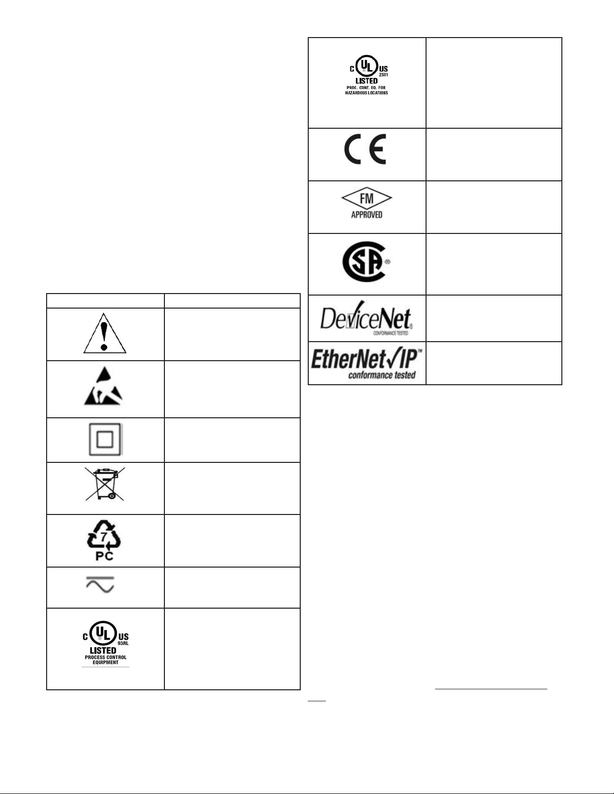
Symbol Explanation
CAUTION – Warning or Hazard
that needs further explanation
than label on unit can provide.
Consult User's Guide for further
information.
ESD Sensitive product, use proper
grounding and handling tech-
niques when installing or servic-
ing product.
Unit protected by double/rein-
forced insulation for shock hazard
prevention.
Do not throw in trash, use proper
recycling techniques or consult
manufacturer for proper disposal.
Enclosure made of Polycarbonate
material. Use proper recycling
techniques or consult manufac-
turer for proper disposal.
Unit can be powered with either
alternating current (ac) voltage or
direct current (dc) voltage.
Unit is a Listed device per Un-
derwriters Laboratories®. It has
been evaluated to United States
and Canadian requirements for
Process Control Equipment. UL
61010 and CSA C22.2 No. 61010.
File E185611 QUYX, QUYX7.
See: www.ul.com
Unit is a Listed device per Un-
derwriters Laboratories®. It has
been evaluated to United States
and Canadian requirements for
Hazardous Locations Class 1
Division II Groups A, B, C and
D. ANSI/ISA 12.12.01-2007. File
E184390 QUZW, QUZW7. See:
www.ul.com
Unit is compliant with European
Union directives. See Declaration
of Conformity for further details
on Directives and Standards used
for Compliance.
Unit has been reviewed and ap-
proved by Factory Mutual as a
Temperature Limit Device per FM
Class 3545 standard. See: www.
fmglobal.com
Unit has been reviewed and ap-
proved by CSA International for
use as Temperature Indicating-
Regulating Equipment per CSA
C22.2 No. 24. See: www.csa-inter-
national.org
Unit has been reviewed and ap-
proved by ODVA for compliance
with DeviceNet communications
protocol. See: www.odva.org
Unit has been reviewed and ap-
proved by ODVA for compliance
with Ethernet/IP communications
protocol. See: www.odva.org
Warranty
The EZ-ZONE®PM is manufactured by ISO
9001-registered processes and is backed by a three-
year warranty to the first purchaser for use, provid-
ing that the units have not been misapplied. Since
Watlow has no control over their use, and some-
times misuse, we cannot guarantee against failure.
Watlow’s obligations hereunder, at Watlow’s option,
are limited to replacement, repair or refund of pur-
chase price, and parts which upon examination prove
to be defective within the warranty period specified.
This warranty does not apply to damage resulting
from transportation, alteration, misuse or abuse. The
purchaser must use Watlow parts to maintain all
listed ratings.
Technical Assistance
If you encounter a problem with your Watlow control-
ler, review your configuration information to verify
that your selections are consistent with your applica-
tion: inputs, outputs, alarms, limits, etc. If the prob-
lem persists, you can get technical assistance from
your local Watlow representative (see back cover), by
e-mailing your questions to wintechsupport@watlow.
com or by dialing +1 (507) 494-5656 between 7 a.m.
and 5 p.m., Central Standard Time (CST). Ask for for
an Applications Engineer. Please have the following
information available when calling:
• Complete model number

• All configuration information
• User's Guide
• Factory Page
Return Material Authorization (RMA)
1. Call Watlow Customer Service, (507) 454-5300, for a
Return Material Authorization (RMA) number before
returning any item for repair. If you do not know why
the product failed, contact an Application Engineer or
Product Manager. All RMA’s require:
• Ship-to address
• Bill-to address
• Contact name
• Phone number
• Method of return shipment
• Your P.O. number
• Detailed description of the problem
• Any special instructions
• Name and phone number of person returning the
product.
2. Prior approval and an RMA number from the Customer
Service Department is required when returning any
product for credit, repair or evaluation. Make sure the
RMA number is on the outside of the carton and on all
paperwork returned. Ship on a Freight Prepaid basis.
3. After we receive your return, we will examine it and try
to verify the reason for returning it.
4. In cases of manufacturing defect, we will enter a repair
order, replacement order or issue credit for material
returned. In cases of customer misuse, we will provide
repair costs and request a purchase order to proceed
with the repair work.
5. To return products that are not defective, goods must
be in new condition, in the original boxes and they must
be returned within 120 days of receipt. A 20 percent
restocking charge is applied for all returned stock con-
trols and accessories.
6. If the unit is not repairable, you will receive a letter of
explanation. and be given the option to have the unit
returned to you at your expense or to have us scrap the
unit.
7. Watlow reserves the right to charge for no trouble found
(NTF) returns.
The EZ-ZONE PM User's Guide is copyrighted by Watlow
Electric, Inc., © April 2013 with all rights reserved.
EZ-ZONE PM is covered by U.S. Patent Numbers:
6005577; D553095; D553096; D553097; D560175; D55766;
and OTHER PATENTS PENDING

Watlow EZ-ZONE®PM Integrated Controller • 1 • Table of Contents
TC Table of Contents
Chapter 1: Overview .....................................4
Standard Features and Benefits ...............................4
Optional Features and Benefits ................................ 5
A Conceptual View of the PM .................................6
Getting Started Quickly....................................7
Chapter 2: Install and Wire................................16
Dimensions..............................................16
Installation.........................................20
Wiring..................................................22
Network Status .....................................36
Module Status ......................................36
Activity Status ......................................36
Link Status ........................................36
Network Status .....................................38
Module Status ......................................38
Chapter 3: Keys and Displays ..............................42
Attention Codes ..........................................43
Chapter 4: Home Page...................................45
Chapter 5: Operations Page ...............................52
Analog Input Menu ........................................ 54
Linearization Menu ........................................54
Process Value Menu.......................................55
Digital Input/Output Menu ..................................56
Limit Menu ..............................................57
Monitor Menu............................................57
Control Loop Menu........................................58
Alarm Menu .............................................61
Current Menu ............................................62
Math Menu ..............................................63
Special Output Function Menu ...............................64
Profile Status Menu .......................................65

Watlow EZ-ZONE®PM Integrated Controller • 2 • Table of Contents
TC Table of Contents (cont.)
Chapter 6: Setup Page ...................................67
Analog Input Menu ........................................ 69
Linearization Menu ........................................71
Process Value Menu.......................................74
Digital Input / Output Menu .................................75
Limit Menu ..............................................79
Control Loop Menu........................................80
Output Menu.............................................85
Alarm Menu .............................................88
Current Menu ............................................91
Math Menu ..............................................92
Special Output Function Menu ...............................93
Function Key.............................................94
Global Menu .............................................95
Communications Menu.....................................98
Real Time Clock Menu ....................................102
Chapter 7: Profiling Page ................................103
Profile Setup............................................103
Starting a Profile.........................................104
Profiling Menu ..........................................107
Chapter 8: Factory Page.................................113
Custom ...............................................114
Lock Menu .............................................114
Unlock Menu ...........................................116
Diagnostics Menu........................................116
Calibration Menu ........................................118
Chapter 9: Features....................................119
Changing PM Integrated Model Number to PM Express ..........121
Tuning the PID Parameters.................................123
Inputs .................................................125
Outputs................................................128
Resetting a Tripped Limit .................................. 130
Control Methods.........................................131
Alarms ................................................136

Watlow EZ-ZONE®PM Integrated Controller • 3 • Table of Contents
Current Sensing .........................................138
Open Loop Detection .....................................138
Programming the EZ Key/s.................................138
Using Lockout and Password Security........................139
Using Lockout Method 1 (Read and Set Lock).................. 139
Using Lockout Method 2 (Password Enable) ...................140
Modbus - Using Programmable Memory Blocks ................ 142
CIP - Communications Capabilities ..........................142
CIP Implicit Assemblies .................................143
Compact Assembly Class ................................ 143
Modifying Implicit Assembly Members .....................143
Profibus DP - (Decentralized Peripherals) .....................144
Software Configuration....................................144
Searching Network for Devices. . . . . . . . . . . . . . . . . . . . . . . . 145
Available Network Devices Displayed...................145
Chapter 10: Applications ................................148
Example 1: Single Loop Control .......................148
Example 2: Sensor Backup...........................148
Example 3: Square Root.............................149
Example 4: Ratio...................................149
Example 5: Differential ..............................150
Example 6: Cascade ................................150
Example 7: Wet Bulb / Dry Bulb .......................152
Example 8: Vaisala .................................152
Example 9: Motorized Valve Control ....................153
Chapter 11: Appendix ..................................154
Troubleshooting Alarms, Errors and Control Issues..............154
Modbus - Programmable Memory Blocks .....................158
CIP Implicit Assembly Structures............................160
Compact Class Assembly Structure ..........................161
Specications .....................................168
Ordering Information for PM Integrated Controller Models ........171
Index..................................................172
How to Reach Us ........................................178
TC Table of Contents (cont.)

Watlow EZ-ZONE®PM Integrated Controller •4 • Chapter 1 Overview
Chapter 1: Overview
1
The EZ-ZONE®PM takes the pain out of solving your thermal loop requirements.
Watlow’s EZ-ZONE PM controllers offer options to reduce system complexity and the cost of control-loop
ownership. You can order the EZ-ZONE PM as a PID controller or an over-under limit controller, or you can
combine both functions in the PM Integrated Limit Controller. You now have the option to integrate a high-
amperage power controller output, an over-under limit controller and a high-performance PID controller all in
space-saving, panel-mount packages. You can also select from a number of serial communications options to
help you manage system performance.
It just got a whole lot easier to solve the thermal requirements of your system. Because the EZ-ZONE PM
controllers are highly scalable, you only pay for what you need. So if you are looking for a PID controller, an
over-under limit controller or an integrated controller, the EZ-ZONE PM is the answer.
Standard Features and Benefits
Advanced PID Control Algorithm
• TRU-TUNE+
®
Adaptive tune provides tighter control for demanding applications.
• Auto Tune for fast, efficient start ups
EZ-ZONE configuration communications and software
• Saves time and improves the reliability of controller set up
FM Approved Over-under Limit with Auxiliary Outputs
• Increases user and equipment safety for over-under temperature conditions
• To meet agency requirements, output 4 is the fixed limit output. Other outputs can be configured to mirror
the limit output (4).
Parameter Save & Restore Memory
• Reduces service calls and down time
Agency approvals: UL Listed, CSA, CE, RoHS, W.E.E.E. FM, SEMI F47-0200, Class 1, Div 2 rating
on selected models
• Assures prompt product acceptance
• Reduces end product documentation costs
EZ-Key/s
• Programmable EZ-Key enables simple one-touch operation of repetitive user activities
Programmable Menu System
• Reduces set up time and increases operator efficiency
Three-year warranty
• DemonstratesWatlow’sreliabilityandproductsupport
Touch-safe Package
• IP2X increased safety for installers and operators
P3T Armor Sealing System
• NEMA 4X and IP66 offers water and dust resistance, can be cleaned and washed down (indoor use only)
• Backed up by UL 50 independent certification to NEMA 4X specification
Removable cage clamp wiring connectors
• Reliable wiring, reduced service calls
• Simplified installation

Watlow EZ-ZONE®PM Integrated Controller •5 • Chapter 1 Overview
Heat-Cool Operation
• Provides application flexibility with accurate temperature and process control
Optional Features and Benefits
High-amperage Power Control Output
• Drives 15 amp resistive loads directly
• Reduces component count
• Saves panel space and simplifies wiring
• Reduces the cost of ownership
Integrated PID and Limit Controller
• Reduces wiring time and termination complexity compared to connecting discrete products
• Decreases required panel space
• Lowers installation costs
• Increases user ad equipment safety for over/under temperature conditions
Current Monitoring
• Detects heater current flow and provides alarm indication of a failed output device or heater load
Serial Communications Capabilities
• Provides a wide range of protocol choices including Modbus
®
RTU, EtherNet/IPTM, PCCC (Programmable
Controller Communications Commands),
DeviceNet
TM, Modbus
®
TCP, and Profibus DP
• Supports network connectivity to a PC or PLC
Dual Channel Controller
• For selected models provides two PID controllers in one space saving package
Enhanced Control Capabilities
• Easily handle complex process problems such as cascade, ratio, differential, square-root, motorized valve
control without slidewire feedback, wet-bulb/dry-bulb and compressor control
Full-featured Alarms
• Improves operator recognition of system faults
• Control of auxiliary devices
Ten Point Linearization Curve
• Improves sensor accuracy
Remote Set Point Operation
• Supports efficient set point manipulation via a master control or PLC
Retransmit Output
• Supports industry needs for product process recording
Profile Capability
• Preprogrammed process control
• Ramp and soak programming with four files and 40 total steps

Watlow EZ-ZONE®PM Integrated Controller •6 • Chapter 1 Overview
A Conceptual View of the PM
The flexibility of the PM’s software and hardware allows a large range of configurations. Acquiring a better
understanding of the controller’s overall functionality and capabilities while at the same time planning out
how the controller can be used will deliver maximum effectiveness in your application.
It is useful to think of the controller in terms of functions; there are internal and external functions. An
input and an output would be considered external functions where the PID calculation or a logic function
would be an internal function. Information flows from an input function to an internal function to an output
function when the controller is properly configured. A single PM controller can carry out several functions
at the same time, for instance closed-loop control, monitoring for several different alarm situations, perform-
ing logical operations and operating switched devices, such as lights and motors. Each process needs to be
thought out carefully and the controller’s various functions set up properly.
Input Functions
The inputs provide the information that any given programmed procedure can act upon. In a simple form,
this information may come from an operator pushing a button or as part of a more complex procedure it may
represent a remote set point being received from another controller.
Each analog input typically uses a thermocouple, thermistor or RTD to read the temperature of some-
thing. It can also read volts, current or resistance, allowing it to use various devices to read humidity, air
pressure, operator inputs and others values. The settings in the Analog Input Menu (Setup Page) for each
analog input must be configured to match the device connected to that input.
Each digital input reads whether a device is active or inactive. A PM with digital input-output (DIO) hard-
ware can include up to eight DIO each of which can be used as either an input or an output. Each DIO must
be configured to function as either an input or output with the Direction parameter in the Digital Input/Out-
put Menu (Setup Page).
The Function or EZ Key on the front panel of the PM also operates as a digital input by toggling the func-
tion assigned to it in the Digital Input Function parameter in the Function Key Menu (Setup Page).
Internal Functions
Functions use input signals to calculate a value. A function may be as simple as reading a digital input to set
a state to true or false, or reading a temperature to set an alarm state to on or off. Or, it could compare the
temperature of a process to the set point and calculate the optimal power for a heater.
To set up an internal function, it’s important to tell it what source, or instance, to use. For example, an
alarm may be set to respond to either analog input 1 or 2 (instance 1 or 2, respectively).
Output Functions
Outputs can perform various functions or actions in response to information provided by a function, such as
operating a heater, driving a compressor, turning a light on or off, unlocking a door etc...
Assign an output to a Function in the Output Menu or Digital Input/Output Menu. Then select which in-
stance of that function will drive the selected output. For example, you might assign an output to respond to
alarm 4 (instance 4) or to retransmit the value of analog input 2 (instance 2).
You can assign more than one output to respond to a single instance of a function. For example, alarm 2
could be used to trigger a light connected to output 1 and a siren connected to digital output 5.
Input Events and Output Events
Input and output events are internal states that are used exclusively by profiles. The source of an event in-
put can come from a real-world digital input or an output from another function. Likewise, event outputs may
control a physical output such as an output function block or be used as an input to another function.

Watlow EZ-ZONE®PM Integrated Controller •7 • Chapter 1 Overview
Getting Started Quickly
The PM control has a page and menu structure that is listed below along with a brief description of its pur-
pose.
Setup Page
Push and hold the up and down keys (¿ ¯)
for 6 seconds to enter. (See the Setup Page
for further information)
Once received, a user would want to setup their control prior
to operation. As an example, define the input type and set
the output cycle time.
Operations Page
Push and hold the up and down keys (¿ ¯)
for 3 seconds to enter. (See the Operations
Page for further information)
After setting up the control to reflect your equipment, the
Operations Page would be used to monitor or change run-
time settings. As an example, the user may want to see how
much time is left in a profile step or perhaps change the
limit high set point.
Factory Page
Push and hold the Infinity and the green Ad-
vance keys (ˆ
‰
) for 6 seconds to enter. (See
the Factory Page for further information)
For the most part the Factory Page has no bearing on the
control when running. A user may want to enable password
protection, view the control part number or perhaps create a
custom Home Page.
Home Page
The control is at the Home Page when ini-
tially powered up.
Pushing the green Advance key
‰
will allow the user to see
and change such parameters as the control mode, enable au-
totune and idle set point to name a few.
Profile Page
Push and hold the the green Advance key
‰
for 6 seconds to enter. (See the Profile Page
for further information)
If equipped with this feature a user would want to go here
to configure a profile.
The default PM loop configuration out of the box is shown below:
• Analog Input functions set to thermocouple, type J
•Heat algorithm set for PID, Cool set to off
•Output 1 set to Heat
•Control mode set to Auto
•Set point set to 75 °F
If you are using the input type shown above, simply connect your input and output devices to the control.
Power up the control and push the up arrow ¿ on the face of the control to change the set point from the
default value of 75 °F to the desired value. As the Set Point increases above the Process Value, output 1 will
come on and it will now begin driving your output device. The PV function as shown in the graphic below is
only available with PM4/8/9 models.
Note:
The output cycle time will have a bearing on the life of mechanical relay outputs and can be different based
on the type of output ordered. The output cycle time can be changed in the Setup Page under the Output
Menu.
EZ-ZONE PM Default Configuration
Heat
Thermocouple Type J
Analog Input 1
PID
Controller
Heat
Loop 1
Input Sensor
Output
Function
Input
Function
Output 1
Process
Value
(PV)
Function
Off

Watlow EZ-ZONE®PM Integrated Controller •8 • Chapter 1 Overview
EZ-ZONE®PM Integrated Model 1/16 DIN System Diagram
With a Current Transformer, Without Communications Card (Slot B)
Note:
Number of inputs and outputs and various combinations of the same will vary
depending upon part number; see ordering matrix for more detail.
EZ Key
Programmable Event
Digital Output (or Input) 5 & 6
(optional) none, switched dc
Digital Input (or Output) 5 & 6
(optional) none, switch, volts dc
Current
Transformer
Board
(optional)
Slot B
Input
Functions
Output
Functions
- None
- Idle set point
- Tune
- Alarm clear, request
- Force alarm
- Silence alarm
- Manual/auto mode
- Control outputs off
- Remote set point
enable
- Lock keypad
- TRU-TUNE+
®
disable
- Loop & alarms off
- Profile disable
- Profile hold/resume
- Profile start
- Profile start/stop
- Restore user settings
- Event inputs
Output Status
5
1
3
2
4
Indicates Zone
Address
Indicates I/O
Status
Zone
Address
Analog Input 1
none, Thermocouple, RTD (100Ω,
1kΩ), Thermistor 5kΩ, 10kΩ, 20kΩ,
40kΩ) Process (V, mV, mA) or 1k
Potentiometer
Output 1
none, switched dc/open collector, 5A
mechanical relay (form C), process
(V, mA), or 0.5A SSR (form A)
Output 2
none, 15A NO-ARC, switched dc,
5A mechanical relay (form A), or
0.5A SSR (form A)
Analog Input 2
Current Transformer
PID
Controller
(Optional -
Ramp/Soak max 4
files, 40 steps)
Slot A
(Optional)
Input Sensor
off, heat, cool
alarm, retransmit,
duplex, event
off, heat, cool
alarm, event
off, heat, cool
alarm, retransmit,
duplex, event
off, heat, cool
alarm, event
off, heat, cool
alarm, event
Modbus
Address
1 - 247
Standard Bus
Zone Address
1 - 16
Supervisory &
Power Board
Slot C
Current
Transformer
EIA-485 Communication
Standard Bus
(optional Modbus RTU)
RUI, EZ-ZONE
Controllers, PLC, PC
or HMI
Output 3
none, switched dc/open collector, 5A
mechanical relay (form C), process
(V, mA), or 0.5A SSR (form A)
Output 4
none, 15A NO-ARC, switched dc,
5A mechanical relay (form A), or
0.5A SSR (form A)
6
Current Monitoring
• detects heater current flow
• provides an alarm indication of a failed-load issue.

Watlow EZ-ZONE®PM Integrated Controller •9 • Chapter 1 Overview
EZ-ZONE®PM Integrated Model 1/16 DIN System Diagram
With Auxillary Input, Without Communications Card (Slot B)
Note:
Number of inputs and outputs and various combinations of the same will vary
depending upon part number; see ordering matrix for more detail.
EZ Key
Programmable Event
Digital Output (or Input) 5 & 6
(optional) none, switched dc
Digital Input (or Output) 5 & 6
(optional) none, switch, volts dc
Auxillary
Input
(optional)
Slot B
Input
Functions
Output
Functions
- None
- Idle set point
- Tune
- Alarm clear, request
- Force alarm
- Silence alarm
- Manual/auto mode
- Control outputs off
- Remote set point
enable
- Lock keypad
- TRU-TUNE+
®
disable
- Loop & alarms off
- Profile disable
- Profile hold/resume
- Profile start
- Profile start/stop
- Restore user settings
- Event inputs
Output Status
5
1
3
2
4
Indicates Zone
Address
Indicates I/O
Status
Zone
Address
Analog Input 1
none, Thermocouple, RTD (100Ω,
1kΩ), Thermistor 5kΩ, 10kΩ, 20kΩ,
40kΩ) Process (V, mV, mA) or 1k
Potentiometer
Output 1
none, switched dc/open collector, 5A
mechanical relay (form C), process
(V, mA), or 0.5A SSR (form A)
Output 2
none, 15A NO-ARC, switched dc,
5A mechanical relay (form A), or
0.5A SSR (form A)
PID
Controller
(Optional -
Ramp/Soak max 4
files, 40 steps)
Slots A
(Optional)
Input Sensor
off, heat, cool
alarm, retransmit,
duplex, event
off, heat, cool
alarm, event
off, heat, cool
alarm, retransmit,
duplex, event
off, heat, cool
alarm, event
off, heat, cool
alarm, event
Modbus
Address 1 - 247
Standard Bus
Zone Address
1 - 16
Supervisory &
Power Board
Slot C
EIA-485 Communication
Standard Bus
(optional Modbus RTU)
RUI, EZ-ZONE
Controllers, PLC, PC
or HMI
Output 3
none, switched dc/open collector, 5A
mechanical relay (form C), process
(V, mA), or 0.5A SSR (form A)
Output 4
none, 15A NO-ARC, switched dc,
5A mechanical relay (form A), or
0.5A SSR (form A)
Analog Input 2
none, CT, Thermocouple, RTD (100
Ω, 1kΩ), Thermistor 5kΩ, 10kΩ,
20kΩ, 40kΩ) Process (V, mV, mA)
or 1k Potentiometer
Input Sensor
6
Remote Set Point Operation
• Supports efficient set point manipulation from a remote device, such as a master control or PLC.

Watlow EZ-ZONE®PM Integrated Controller •10 • Chapter 1 Overview
EZ-ZONE®PM Integrated Model 1/16 DIN With Limit, System Diagram
Without Communications Card (Slot B)
Note:
Number of inputs and outputs and various combinations of the same will vary
depending upon part number; see ordering matrix for more detail.
EZ Key
Programmable Event
Digital Output (or Input) 5 & 6
(optional) none, switched dc
Digital Input (or Output) 5 & 6
(optional) none, switch, volts dc
Limit Controller
Board
(optional)
Slot B
Input
Functions
Output
Functions
- None
- Limit reset
- Idle set point
- Tune
- Alarm clear, request
- Force alarm
- Silence alarm
- Manual/auto mode
- Control outputs off
- Remote set point
enable
- Lock keypad
- TRU-TUNE+®disable
- Loop & alarms off
- Profile disable
- Profile hold/resume
- Profile start
- Profile start/stop
- Restore user settings
- Event inputs
Output Status
5
1
3
2
4
Indicates Zone
Address
Indicates I/O
Status
Zone
Address
Analog Input 1
none, Thermocouple, RTD (100Ω,
1kΩ), Thermistor 5kΩ, 10kΩ, 20kΩ,
40kΩ) Process (V, mV, mA) or 1k
Potentiometer
Output 1
none, switched dc/open collector, 5A
mechanical relay (form C), process
(V, mA), or 0.5A SSR (form A)
Output 2
none, 15A NO-ARC, switched dc,
5A mechanical relay (form A), or
0.5A SSR (form A)
PID
Controller
(Optional -
Ramp/Soak max 4
files, 40 steps)
Slots A
(Optional)
Input Sensor
off, heat, cool
alarm, retransmit,
duplex, event
off, heat, cool
alarm, event
off, heat, cool
alarm, retransmit,
duplex or event
Limit
off, heat, cool
alarm, event
Modbus
Address 1 - 247
Standard Bus
Zone Address
1 - 16
Supervisory &
Power Board
Slot C
EIA-485 Communication
Standard Bus
(optional Modbus RTU)
RUI, EZ-ZONE
Controllers, PLC, PC
or HMI
Output 3
none, switched dc/open collector, 5A
mechanical relay (form C), process
(V, mA), or 0.5A SSR (form A)
Output 4
5A mechanical relay (form A)
Analog Input 2
none, CT, Thermocouple, RTD (100
Ω, 1kΩ), Thermistor 5kΩ, 10kΩ,
20kΩ, 40kΩ) Process (V, mV, mA)
or 1k Potentiometer
Input Sensor
If Limit, this output must
be Limit
6
Integrated PID and Limit Controller
• Reduces wiring time and termination complexity compared to connecting separate products
• Reduces panel space
• Reduces installation costs
• Increases dependability with backup control sensor operation
• Increases user and equipment safety for over-under temperature conditions

Watlow EZ-ZONE®PM Integrated Controller •11 • Chapter 1 Overview
EZ-ZONE®PM Integrated Model 1/16 DIN System Diagram
with Expanded Communications (Slot B)
Note:
Number of inputs and outputs and various combinations of the same will vary
depending upon part number; see ordering matrix for more detail.
EZ Key
Programmable Event
Digital Output (or Input) 5 & 6
(optional) none, switched dc
Digital Input (or Output) 5 & 6
(optional) none, switch, volts dc
Input
Functions
Output
Functions
- None
- Idle set point
- Tune
- Alarm clear, request
- Force alarm
- Silence alarm
- Manual/auto mode
- Control outputs off
- Remote set point
enable
- Lock keypad
- TRU-TUNE+®disable
- Loop & alarms off
- Profile disable
- Profile hold/resume
- Profile start
- Profile start/stop
- Restore user settings
- Event inputs
Output Status
5
1
3
2
4
Indicates Zone
Address
Indicates I/O
Status
Zone
Address
Analog Input 1
none, CT, Thermocouple, RTD (100
Ω, 1kΩ), Thermistor 5kΩ, 10kΩ,
20kΩ, 40kΩ) Process (V, mV, mA)
or 1k Potentiometer
Output 1
none, switched dc/open collector, 5A
mechanical relay (form C), process
(V, mA), or 0.5A SSR (form A)
Output 2
none, 15A NO-ARC, switched dc,
5A mechanical relay (form A), or
0.5A SSR (form A)
PID
Controller
(Optional -
Ramp/Soak max 4
files, 40 steps)
Slot A
(Optional)
Input Sensor
off, heat, cool
alarm, retransmit,
duplex, event
off, heat, cool
alarm, event
off, heat, cool
alarm, event
EIA-485 Communication
Standard Bus
(optional Modbus RTU)
RUI, EZ-ZONE
Controllers, PLC, PC
or HMI
Communications
EIA 232/485 Modbus RTU/TCP,
EtherNet/IP, DeviceNet, Profibus
Modbus Address
1 - 247
Standard Bus
Zone Address
1 - 16
Supervisory &
Power Board
Slot C
Communications
Board
Slot B
6
Serial Communication Capabilities
• Supports network connectivity to a PC or PLC
• Available in a wide range of protocol choices, including Modbus RTU, EtherNet/IP™, Modbus TCP

Watlow EZ-ZONE®PM Integrated Controller •12 • Chapter 1 Overview
EZ-ZONE®PM Integrated Model 1/8 and 1/4 DIN System Diagram
Without 6 Digital I/O (slot D), Without Communications (slot E)
EZ-ZONE PM Integrated 8th DIN System Diagram
Without 6-digital I/O (slot D), Without Comms Card (slot E)
Input
Function
Output
Function
If limit, this output
must be limit
Output 4
none, 15A NO-ARC, switched dc,
5A mechanical relay (form A), or
0.5A SSR (form A)
Output 1
none, switched dc/open collector,
5A mechanical relay (form C),
process, or 0.5A SSR (form A)
Analog Input 1
none, Thermocouple, RTD (100Ω,
1kΩ), Thermistor 5kΩ, 10kΩ, 20kΩ,
40kΩ) Process (V, mV, mA) or 1k
Potentiometer
PID
Controller
(Optional -
Ramp/Soak max 4
files, 40 steps)
Slots A
(Optional)
100 to 240Vac
20 to 28 Vac or 12 to 40Vdc
Modbus
Address 1 - 247
Standard Bus
Zone Address
1 - 16
Supervisory &
Power Board
Slot C
Input Sensor
EIA-485 Communication
Standard Bus
(optional Modbus RTU)
RUI, EZ-ZONE
Controllers, PLC, PC
or HMI
off, heat, cool,
retransmit, alarm,
duplex or event
off, heat, cool,
alarm, event or
limit
Output Status
LEDs
5
6
1
3
2
4
Zone
Address
LEDs
Channel
Indicates Zone
Address & Channel
Indicates I/O
Status
off, heat, cool,
alarm, or event
8
7
PID Controller,
Limit, or Current
Transformer Sense
(CT)
Slots B
(Optional)
Analog Input 2
none, CT, Thermocouple, RTD (100
Ω, 1kΩ), Thermistor 5kΩ, 10kΩ,
20kΩ, 40kΩ) Process (V, mV, mA)
or 1k Potentiometer
Input Sensor
Output 2
none, 15A NO-ARC, switched dc,
5A mechanical relay (form A), or
0.5A SSR (form A)
Output 3
none, switched dc/open collector,
5A mechanical relay (form C),
process, or 0.5A SSR (form A)
off, heat, cool,
retransmit, alarm,
duplex or event
off, heat, cool,
alarm or event
Power Supply
Note:
Number of inputs and outputs and various combinations of the same will vary
depending upon part number; see ordering matrix for more detail.
Digital Input (or Output) 5 & 6 (optional)
Programmable Functions
EZ Key 1 & 2
Programmable Functions
Digital Output (or Input) 5 & 6
(optional) none, switched dc
- None
- Limit reset
- Idle set point
- Tune
- Alarm clear, request
- Silence alarm
- Manual/auto mode
- Control mode
- Remote set point
enable
- Lock keypad
- Force alarm
- TRU-TUNE+
®disable
- Loop & alarms off
- Profile disable
- Profile hold/resume
- Profile start
- Profile start/stop
- Restore user settings
- Event inputs
- Math

Watlow EZ-ZONE®PM Integrated Controller •13 • Chapter 1 Overview
EZ-ZONE®PM Integrated Model 1/8 and 1/4 DIN System Diagram
With 6 Digital I/O (slot D), Without Communications (slot E)
Input
Function
Output
Function
off, heat, cool
alarm, retransmit,
duplex or event
EZ-ZONE PM Integrated 8th DIN System Diagram
With 6-digital I/O (slot D), Without Comms Card (slot E)
Analog Input 1
none, Thermocouple, RTD (100Ω,
1kΩ), Thermistor 5kΩ, 10kΩ, 20kΩ,
40kΩ) Process (V, mV, mA) or 1k
Potentiometer
PID Controller,
Limit, or
Current Trans-
former Sense
(CT)
Slots B
(Optional)
PID
Controller
(Optional -
Ramp/Soak max
4 files, 40 steps)
Slots A
(Optional)
Input Sensor
Output 2
none, 15A NO-ARC, switched dc,
5A mechanical relay (form A), or
0.5A SSR (form A)
Analog Input 2
none, CT, Thermocouple, RTD (100
Ω, 1kΩ), Thermistor 5kΩ, 10kΩ,
20kΩ, 40kΩ) Process (V, mV, mA)
or 1k Potentiometer
6 - Digital
Inputs / Outputs
Slot D
(Optional)
Power Supply
100 to 240Vac
20 to 28 Vac or 12 to 40Vdc
Modbus
Address 1 - 247
Standard Bus
Zone Address
1 - 16
Supervisory &
Power Board
Slot C
EIA-485 Communication
Standard Bus
(optional Modbus RTU)
RUI, EZ-ZONE
Controllers, PLC, PC
or HMI
Output Status
LEDs
5
6
1
3
2
4
Zone
Address
LEDs
Channel
Indicates Zone
Address & Channel
Indicates I/O
Status
8
7
Input Sensor
If limit, this output
must be limit
Output 1
none, switched dc/open collector, 5A
mechanical relay (form C), process
(V, mA), or 0.5A SSR (form A)
off, heat, cool
alarm or event
Output 3
none, switched dc/open collector, 5A
mechanical relay (form C), process
(V, mA), or 0.5A SSR (form A)
off, heat, cool
alarm, event or limit
off, heat, cool
alarm, retransmit,
duplex or event
Output 4
none, 15A NO-ARC, switched dc,
5A mechanical relay (form A), or
0.5A SSR (form A)
off, heat, cool
alarm or event
off, heat, cool
alarm or event
Digital Input (or Output) 7-12 (optional)
Programmable Functions
Digital Output (or Input) 7-12
(optional) none, switched dc
Digital Input (or Output) 5 & 6 (optional)
Programmable Functions
EZ Key 1 & 2
Programmable Functions
- None
- Limit reset
- Idle set point
- Tune
- Alarm clear, request
- Silence alarm
- Manual/auto mode
- Control mode
- Remote set point
enable
- Lock keypad
- Force alarm
- TRU-TUNE+®disable
- Loop & alarms off
- Profile disable
- Profile hold/resume
- Profile start
- Profile start/stop
- Restore user settings
- Event inputs
- Math
Digital Output (or Input) 5 & 6
(optional) none, switched dc
Note:
Number of inputs and outputs and various combinations of the same will vary
depending upon part number; see ordering matrix for more detail.

Watlow EZ-ZONE®PM Integrated Controller •14 • Chapter 1 Overview
EZ-ZONE®PM Integrated Model 1/8 and 1/4 DIN with CT System Diagram
Without 6 Digital I/O (slot D), Without Communications (slot E)
EZ-ZONE PM Integrated 8th DIN with CT System Diagram
Without 6-digital I/O (slot D), Without Comms Card (slot E)
Input
Function
Output
Function
If limit, this output
must be limit
Output 4
none, 15A NO-ARC, switched dc,
5A mechanical relay (form A), or
0.5A SSR (form A)
Output 1
none, switched dc/open collector,
5A mechanical relay (form C),
process, or 0.5A SSR (form A)
Analog Input 1
none, Thermocouple, RTD (100Ω,
1kΩ), Thermistor 5kΩ, 10kΩ, 20kΩ,
40kΩ) Process (V, mV, mA) or 1k
Potentiometer
PID
Controller
(Optional -
Ramp/Soak max 4
files, 40 steps)
Slots A
(Optional)
Power Supply
100 to 240Vac
20 to 28 Vac or 12 to 40Vdc
Modbus
Address 1 - 247
Standard Bus
Zone Address
1 - 16
Supervisory &
Power Board
Slot C
Input Sensor
EIA-485 Communication
Standard Bus
(optional Modbus RTU)
RUI, EZ-ZONE
Controllers, PLC, PC
or HMI
off, heat, cool,
retransmit, alarm,
duplex or event
off, heat, cool,
alarm, event or
limit
Output Status
LEDs
5
6
1
3
2
4
Zone
Address
LEDs
Channel
Indicates Zone
Address & Channel
Indicates I/O
Status
off, heat, cool,
alarm, or event
8
7
Current Transformer
Sense (CT)
Slots B
(Optional)
Analog Input 2
Current Transformer
Current
Transformer
Output 2
none, 15A NO-ARC, switched dc,
5A mechanical relay (form A), or
0.5A SSR (form A)
Output 3
none, switched dc/open collector,
5A mechanical relay (form C),
process, or 0.5A SSR (form A)
off, heat, cool,
retransmit, alarm,
duplex or event
off, heat, cool,
alarm or event
Note:
Number of inputs and outputs and various combinations of the same will vary
depending upon part number; see ordering matrix for more detail.
Digital Input (or Output) 5 & 6 (optional)
Programmable Functions
EZ Key 1 & 2
Programmable Functions
Digital Output (or Input) 5 & 6
(optional) none, switched dc
- None
- Idle set point
- Tune
- Alarm clear, request
- Silence alarm
- Manual/auto mode
- Control mode
- Remote set point
enable
- Lock keypad
- Force alarm
- TRU-TUNE+®disable
- Loop & alarms off
- Profile disable
- Profile hold/resume
- Profile start
- Profile start/stop
- Restore user settings
- Event inputs
- Math

Watlow EZ-ZONE®PM Integrated Controller •15 • Chapter 1 Overview
EZ-ZONE®PM Integrated Model 1/8 and 1/4 DIN System Diagram
Without 6 Digital I/O (slot D), With Communications (slot E)
EZ-ZONE PM Integrated 8th DIN System Diagram
Without 6-digital I/O (slot D), With Comms Card (slot E)
Input
Function
Output
Function
If limit, this output
must be limit
Output 4
none, 15A NO-ARC, switched dc,
5A mechanical relay (form A), or
0.5A SSR (form A)
Output 1
none, switched dc/open collector,
5A mechanical relay (form C),
process, or 0.5A SSR (form A)
Analog Input 1
none, Thermocouple, RTD (100Ω,
1kΩ), Thermistor 5kΩ, 10kΩ, 20kΩ,
40kΩ) Process (V, mV, mA) or 1k
Potentiometer
PID
Controller
(Optional -
Ramp/Soak max 4
files, 40 steps)
Slots A
(Optional)
Power Supply
100 to 240Vac
20 to 28 Vac or 12 to 40Vdc
Modbus
Address 1 - 247
Standard Bus
Zone Address
1 - 16
Supervisory &
Power Board
Slot C
Input Sensor
EIA-485 Communication
Standard Bus
(optional Modbus RTU)
RUI, EZ-ZONE
Controllers, PLC, PC
or HMI
off, heat, cool,
retransmit, alarm,
duplex or event
off, heat, cool,
alarm, event or
limit
Output Status
LEDs
5
6
1
3
2
4
Zone
Address
LEDs
Channel
Indicates Zone
Address & Channel
Indicates I/O
Status
off, heat, cool,
alarm, or event
8
7
PID Controller,
Limit, or Current
Transformer Sense
(CT)
Slots B
(Optional)
Analog Input 2
none, CT, Thermocouple, RTD (100
Ω, 1kΩ), Thermistor 5kΩ, 10kΩ,
20kΩ, 40kΩ) Process (V, mV, mA)
or 1k Potentiometer
Input Sensor
Output 2
none, 15A NO-ARC, switched dc,
5A mechanical relay (form A), or
0.5A SSR (form A)
Output 3
none, switched dc/open collector,
5A mechanical relay (form C),
process, or 0.5A SSR (form A)
off, heat, cool,
retransmit, alarm,
duplex or event
off, heat, cool,
alarm or event
Communications
Board
Slots E
(Optional)
Communications
Modbus RTU/TCP, DeviceNet,
EtherNet/IP, Profibus
Note:
Number of inputs and outputs and various combinations of the same will vary
depending upon part number; see ordering matrix for more detail.
Digital Input (or Output) 5 & 6 (optional)
Programmable Functions
EZ Key 1 & 2
Programmable Functions
Digital Output (or Input) 5 & 6
(optional) none, switched dc
- None
- Limit reset
- Idle set point
- Tune, TRU-TUNE+
®
- Alarm clear, request
- Silence alarm
- Manual/auto mode
- Control mode
- Remote set point
enable
- Lock keypad
- Force alarm
- Loop & alarms off
- Profile disable
- Profile hold/resume
- Profile start
- Profile start/stop
- Restore user settings
- Event inputs
- Math

Watlow EZ-ZONE®PM Integrated Controller •16 • Chapter 2 Install and Wire
Chapter 2: Install and Wire
2
Dimensions
1/16 DIN (PM6)
L1
K1
J1
L2
K2
T1
S1
R1
L3
K3
J3
L4
K4
T2
S2
R2
98
99
CF
CD
CE
B5
D6
D5
15.8 mm
(0.62 in)
101.6 mm
(4.00 in) 53.3 mm
(2.10 in)
53.3 mm
(2.10 in)
51.2 mm
(2.02 in)
Side Front
Top Back
1/16 DIN (PM6) Recommended Panel Spacing
Recommended panel spacing
panel thickness 1.53 to 9.52 mm
(0.060 to 0.375)
44.96 to 45.47 mm
(1.77 to 1.79 inches)
44.96 to 45.47 mm
(1
.77 to 1.79 inches)
21.6 mm
(0.85 in)
minimum
21.6 mm
(0.85 in)
minimum

Watlow EZ-ZONE®PM Integrated Controller •17 • Chapter 2 Install and Wire
1/8 DIN (PM8) Vertical Dimensions
(3.95 in)
100.33 mm
(2.16 in)
54.8 mm
(2.10 in)
53.34 mm
(4.00 in)
101.60 mm
(0.62 in)
15.75 mm
(0.06 in)
1.52 mm
(0.40 in)
10.16 mm
(1.21 in)
30.73 mm
1/8 DIN (PM8) Vertical Recommended Panel Spacing
Panel thickness (0.060 in) 1.53 mm
to (0.375 in) 9.52 mm
21.6 mm
(0.85 in)
Minimum
21.6 mm
44.96 to 45.60 mm
(1.77 to 1.79 inches)
92.00 to 92.80 mm
(3.62 to 3.65 inches)
(0.85 in)
Minimum
Table of contents
Other Watlow Electric Controllers manuals


Popular Controllers manuals by other brands

LEGRAND
LEGRAND Wattstopper LMPL-101 installation instructions

ABB
ABB PSTX30 Spare part instruction

SCHUNK
SCHUNK SRU-plus Assembly guide

EWS
EWS EC3020 instruction manual

dixell
dixell XC660D Installing and operating instructions

Outback Power Systems
Outback Power Systems MX60 Installation, programming, and user's manual

Smarteh
Smarteh Longo LPC-2.A03 user manual

Dahua
Dahua DHI-ARC3008C user manual

Truma
Truma MonoControl CS Gastank Operating instructions & installation instructions

Lumiax
Lumiax Smart CC Series user manual

JLCooper Electronics
JLCooper Electronics TransportPro RS422 user manual

HTD
HTD MC-66 Multi-Zone owner's manual


