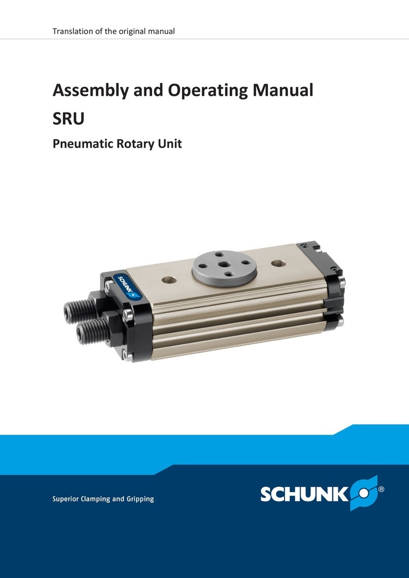
Montageanleitung
Assembly Manual
SRU-plus
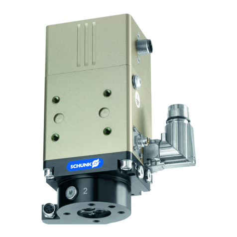
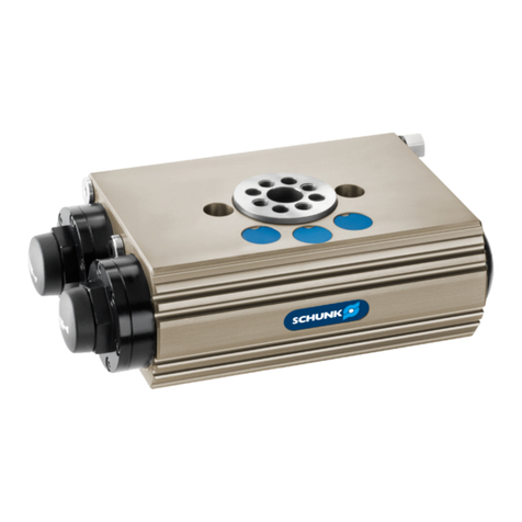
Pneumatische Schwenkeinheit
Pneumatic Swivel Unit
Dear customer,
thank you for trusting our products and our
family-owned company, the leading technology
supplier of robots and production machines.
Our team is always available to answer any
questions on this product and other solutions.
Ask us questions and challenge us. We will find
a solution!
Best regards,
Your SCHUNK team
Copyright:
This manual is protected by copyright. The au-
thor is SCHUNK GmbH & Co. KG. All rights re-
served. Any reproduction, processing, distribu-
tion (making available to third parties), transla-
tion or other usage - even excerpts - of the
manual is especially prohibited and requires
our written approval.
Technical changes:
We reserve the right to make alterations for the
purpose of technical improvement.
© SCHUNK GmbH & Co. KG
All rights reserved.
Document number:0389710
Edition:01.00|28/02/2018|de-en
SCHUNK GmbH & Co. KG
Spann- und Greiftechnik
Bahnhofstr. 106 – 134
D-74348 Lauffen/Neckar
Tel.+49-7133-103-0
Fax +49-7133-103-2399
schunk.com
Further informations and documents as well as detailed
assembly and operating instructions for the product can be
downloaded at schunk.com
1 Variants
This operating manual applies to the following variations:
– SRU-plus/SRU-plus D
– SRU-plus Rotating angle 90°
– SRU-plus Rotating angle 180°
– SRU-plus End position adjustability 3°
– SRU-plus End position adjustability 90°
– SRU-plus with fluid feed-through
– SRU-plus with pneumatic center positioning (M)
– SRU-plus with locked center position (VM)
– SRU-plus with electrical feed-through (EDF)
2 Applicable documents
– General terms of business*
– Catalog data sheet of the purchased product *
– Assembly and operating manual for the product including
declaration of incorporation *
– Assembly and operating manuals of the accessories *
The documents marked with an asterisk (*) can be downloaded
on our homepage schunk.com
3 Basic safety notes
3.1 Intended use
The product may only be used for swiveling permissible attach-
ment parts or workpieces.
– The product may only be used within the scope of its tech-
nical data, }Chap.4, Technical data.
– When implementing and operating components in safety-re-
lated parts of the control systems, the basic safety principles
in accordance with DIN EN ISO 13849-2 apply. The proven
safety principals in accordance with DIN EN ISO 13849-2 also
apply to categories 1, 2, 3 and 4.
– The product is intended for installation in a machine/system. The
applicable guidelines must be observed and complied with.
– The product is intended for industrial and industry-oriented
use.
– Appropriate use of the product includes compliance with all
instructions in this manual.
3.2 Personnel qualification
– All work may only be performed by qualified personnel.
– Before working with the product, the personnel must have
read and understood the complete assembly and operating
manual.
3.3 Personal protective equipment
– When working on and with the product, observe the occu-
pational health and safety regulations and wear the required
personal protective equipment.
– Wear protective gloves to guard against sharp edges and
corners or rough surfaces.
– Wear heat-resistant protective gloves when handling hot
surfaces.
– Wear close-fitting protective clothing and wear long hair in a
hairnet when dealing with moving components.
3.4 Constructional changes
– Constructional changes may only be done with the permis-
sion of SCHUNK.
3.5 Notes for transport
– When handling heavy weights, use lifting equipment to lift
the product and transport it by appropriate means.
– Secure the product against falling during transportation and
handling.
– Stand clear of suspended loads.
3.6 Notes for assembly
– Before assembly, secure the danger zone by suitable measures.
– Switch off the power supply before mounting work, ensure
that no residual energy is present and secure against recon-
nection.
3.7 Notes for operation
– Observe safety distances.
– Never put safety devices out of operation.
– When the power supply is connected, do not move parts by
hand.
– Observe applicable country-specific safety and accident pre-
vention regulations.
Possible electrostatic energy
Components or assembly groups may become electrostatically
charged. When the electrostatic charge is touched, the dis-
charge may trigger a shock reaction leading to injuries.
– The operator must ensure that all components and assembly
groups are included in the local potential equalisation in ac-
cordance with the applicable regulations.
– While paying attention to the actual conditions of the working
environment, the potential equalisation must be implemented
by a specialist electrician according to the applicable regulations.
– The effectiveness of the potential equalisation must be veri-
fied by executing regular safety measurements.
4 Technical data
4.1 Basic data
Designation Value
Noise emission [dB(A)] ≤ 70
Pressure medium Compressed air, compressed air quality
according to ISO 8573-1:7 4 4
Min. pressure [bar] See catalog data sheet
Max. pressure [bar] See catalog data sheet
Basic EDF data
Designation Value
Max. voltage [V] 24
Max. current per wire [A] 1
Maximum transmission rate
PROFIBUS [MBaud] 1.5
The catalog contains diagrams for designing the maximum per-
missible mass moment of inertia.
The SCHUNK contact person provides support for designing fur-
ther applications.
More technical data is included in the catalog data sheet.
Whichever is the latest version.
5 Design
Design
1 Housing 10 Pinion for fluid feed-through
2 Back stops (0° - 180°) 11 Monitoring with movable cam
3 Back stops (0° - 90°) 12 Monitoring with fixed cam
4 Pinion 13 Sensor holder with sensor
5 Piston with shock absorbers 14 Attaching center position
(0°-90°-180°)
6 Cover 15 Back stops locked center position
7 Cover 16 Pistions with shock absorbers
locked center position
8 Clamp shells* 17 Attaching locked
center position (0°-90°-180°)
9 Flange for fluid feed-through
* The variant "explosion-protected version" does not contain a clamp
shell. It is clamped by an eccentric.
5.1 Variant with electrical feed-through (EDF)
Assembly with EDF
1 Base unit with fluid feed-through 5 Monitoring with movable cam
2 EDF flange 6 Monitoring with fixed cam
3 EDF flange, version "D" 7 Distributor plate
4 Sensor holder with sensor 8 Distributor plate, version "D"
6 Assembly
6.1 Assembling and connecting
WARNING
Risk of injury due to unexpected movement of the
machine/system!
With a horizontal swiveling axis, secure locking is not guaran-
teed during the ventilation stage when a swivelling move-
ment is being performed from 3 o'clock (180°) to 6 o'clock
(90°) or from 9 o'clock (0°) to 6 o'clock (90°).
•Screw the separating sleeves into air connections "A" and "B".
•Control both piston chambers of the "A" and "B" air con-
nections separately for the purpose of holding torque.
NOTICE
Risk of damage to the product!
If the end position is approached too hard, the product may
be damaged.
•As a rule, a rotary movement must take place without
impact and bouncing.
•To do this, carry out sufficient throttle and dampening.
•Observe specifications in the catalog data sheet.
NOTICE
Risk of damage to the product!
If during first actuation the exhaust throttle valves are open,
the product may move in an uncontrolled manner.
•Before actuation, check that the exhaust throttle valves are
closed and if necessary close any open ones completely.
ØScrew on rotary actuator, }Chap.6.2.1, Mechanical connection.
ðUse centering sleeves.
ðObserve the tightening torque for the mounting screws,
see tightening torque table.
ØScrew attachment on the pinion with two fitting screws and
two mounting screws, }Chap.6.2.1, Mechanical connection.
ØIn air connections "A" and "B", screw in throttle valves and
connect compressed air lines.
Or with hose-free direct connection:
Screw locking screws into air connections "A" and
"B", }Chap.6.2.2, Pneumatic connection.
Mount throttle valves in the supply lines "a" and "b".
ØScrew in locking screws in open and not required air
connections where appropriate.
ØWith the variant with electrical feed-through (EDF), con-
nect connection cable, }Chap.6.2.3, Electrical connection.
ØFor application cases with horizontal swivel axes, mount
separating sleeves, }Chap.6.3, Mounting separating
sleeve.
ØAdjust angle of rotation, }Chap.6.4.1, Adjust swivel angle.
ØAdjust swiveling speed, }Chap.6.4.2, Adjust swiveling
speed.
ØAdjust absorber stroke, }Chap.6.4.3, Adjust absorber
stroke.
ØMount sensor if necessary, }Chap.6.5, Installing the
sensors.
6.2 Connections
6.2.1 Mechanical connection
NOTE
Adapter plates between the product and the machine/sys-
tem as well as the product and the attachment part must be
made of high-strength aluminum or steel. The tolerance
class for the fitting bore is H7.
Connections on
housing
The product can be assembled from two sides.
– On the attachment side via through-bores (1)
– On the side of the apparatus via threaded holes (2)
Centering sleeves for the mounting screws are included in the
accessory pack.
Assembling possibilities
Item Mounting
SRU-plus
20 25 30 35 40 50 60
1 Mounting screws M8 M8 M8 M8 M10 M12 M12
Max. screw-in depth from
locating surface [mm]
24 24 24 24 25 25 25
2 Centering sleeves Ø12 Ø12 Ø12 Ø12 Ø14 Ø16 Ø16
Attachment connections without fluid feed-through
Attachment connection without fluid feed-through
A Screw connection diagram
SRU-plus
B Screw connection diagram
SRU-plus, compatible with OSE
Item Designation
SRU-plus
20 25 30 35 40 50 60
1 Thread for mounting screws M5 M6 M6 M6 M8 M10 M10
Max. depth of engagement
from locating surface [mm]
9 10 9 10 9 15 15
2 Centering sleeve Ø6 Ø6 Ø6 Ø6 Ø8 Ø10 Ø10
3 Thread for mounting screws M5 M6 M6 M6 M6 M8 M8
Max. depth of engagement
from locating surface [mm]
9 9 9 9 11 13 13
4 Threads for fitting screws M5 M5 M5 M5 M6 M8 M8
Max. depth of engagement
from locating surface [mm]
10 10 10 10 11 17 20
Attachment connections with fluid feed-through
Attachment connection with fluid feed-through up to size 30,
example size 25
Attachment connection with fluid feed-through up to size 35,
example size 50
A Screw connection diagram
SRU-plus
B Screw connection diagram
SRU-plus, compatible with OSE
Item Designation
SRU-plus
20 25 30 35 40 50 60
1 Thread for mounting screws M5 M5 M5 M6 M8 M10 M10
Max. depth of engagement
from locating surface [mm]
9 9 9 10 9 15 15
2 Thread for mounting screws M5 M5 M5 M5 M6 M8 M8
Max. depth of engagement
from locating surface [mm]
9.5 9 9 9 11 13 13
3 Centering sleeve Ø8 Ø8 Ø8 Ø6 Ø8 Ø10 Ø10
4 Threads for fitting screws – – – M5 M6 M8 M8
Max. depth of engagement
from locating surface [mm]
– – – 10 11 20 20
6.2.1.1 Variant with electrical feed-through (EDF)
With the variant with electrical feed-through (EDF), it can only be
assembled on the side of the apparatus via the threaded hole.
Assembly option
1 Threaded holes
assembly on the apparatus side
2 Customer's adapter plate
Attachment connection
If the hose-free direct connection is used, the set-screws must
be removed.
With the variant with electrical feed-through, assembly of the
attachment with fitting screws is not possible.
Attachment connection
1 Set-screw 2 Side air connection
6.2.2 Pneumatic connection
NOTE
• Observe the requirements for the compressed air supply,
}Chap.4, Technical data.
• In case of compressed air loss (cutting off the energy line),
the components lose their dynamic effects and do not
remain in a secure position. However, the use of a SDV-P
pressure maintenance valve is recommended in this case in
order to maintain the dynamic effect for some time.
Product variants are also offered with mechanical gripping
force via springs, which also ensure a minimum clamping
force in the event of a pressure drop.
Air connections, variant with center position
Designation Function
Hose-free direct connection
a Swiveling 0° -90° / 0° - 180°
b Swiveling 90° - 0° / 180° - 0°
c Approach center position (M)
Extend locking position (VM)
d
Hose connection
A Swiveling 0° -90° / 0° - 180°
B Swiveling 90° - 0° / 180° - 0°
C Approach center position (M)
Extend locking position (VM)
D
– Only open the air connections required.
– Seal those main air connections that are not needed using
the locking screws from the accessory pack.
– For hose-free direct connections, use the O-rings from the ac-
cessory pack.
– Use throttle valve from the accessory pack for the main air
connections.
– With hose-free direct connections, throttle valves must be
fitted in front of the main air connections.
Pay attention to the following table when using throttle valves.
