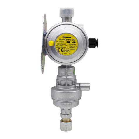
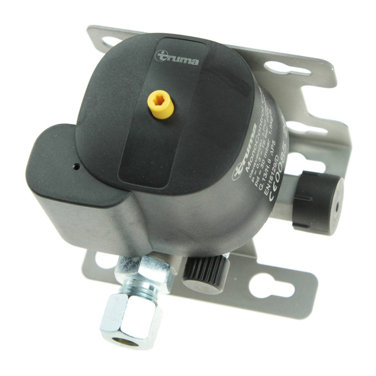
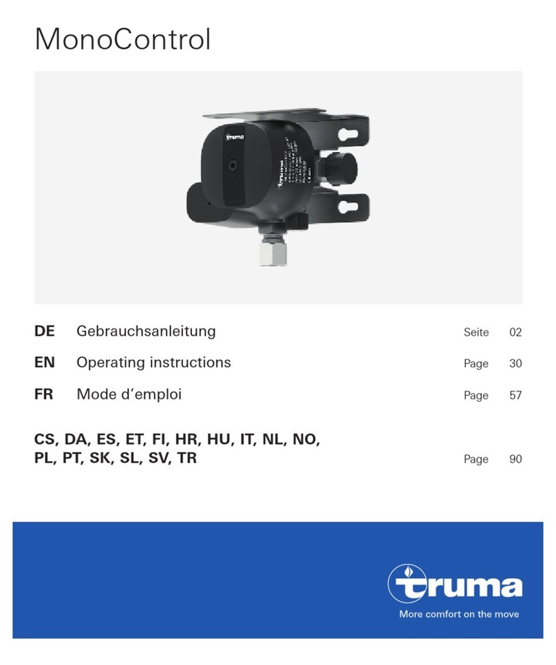
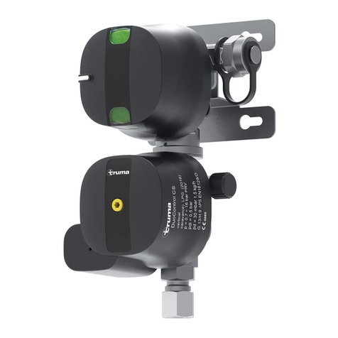
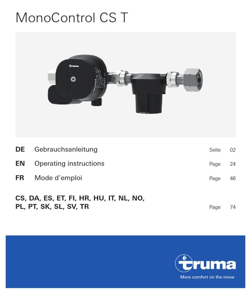
Truma MonoControl CS Gastank Operating instructions

Page 51
MonoControl CS Gastank
Gebrauchsanweisung Seite 2
Einbauanweisung Seite 6
Im Fahrzeug mitzuführen!
Operating instructions Page 9
Installation instructions Page 12
To be kept in the vehicle!
Mode d‘emploi Page 16
Instructions de montage Page 20
À garder dans le véhicule !
Istruzioni per l‘uso Pagina 24
Istruzioni di montaggio Pagina 27
Da tenere nel veicolo!
Gebruiksaanwijzing Pagina 30
Inbouwhandleiding Pagina 33
Im vertuig meenemen!
Brugsanvisning Side 37
Monteringsanvisning Side 40
Skal medbringes i køretøjet!
Instrucciones de uso Página 43
Instrucciones de montaje Página 47
¡Llévalas en el vehículo!

2
MonoControl CS Gastank
Die Druckregelgeräte und Schlauchleitungen müssen
spätestens 10 Jahre (bei gewerblicher Nutzung 8 Jahre)
nach Herstellungsdatum gegen neue ausgewechselt werden.
Der Betreiber ist dafür verantwortlich.
* entspricht bei einem mittleren Fahrzeuggewicht einer Auf-
prallgeschwindigkeit von ca. 15 – 20 km/h auf ein festes
Hindernis.
Hinweise zum Heizen während der Fahrt:
Bei Motorcaravans ab Baujahr 01/2007 muss gemäß der Heiz-
geräterichtlinie 2001/56/EG mit den Ergänzungen 2004/78/EG
und 2006/119/EG für den Betrieb einer Flüssiggasheizung
während der Fahrt, eine Sicherheits-Absperreinrichtung vorge-
sehen werden, welche bei einem Leitungsabriss durch Unfall
verhindert, dass ungewollt Gas austreten kann.
Die Truma Gasdruck-Regelanlage MonoControl CS Gastank
mit integriertem Crashsensor, erfüllt alle relevanten Normen,
Vorschriften und Richtlinien und erlaubt somit den europawei-
ten Betrieb der Gasanlage, auch während der Fahrt.
Für das Heizen während der Fahrt in Caravans empfehlen wir
ebenfalls die Verwendung einer Sicherheitseinrichtung.
Für Fahrzeuge vor Baujahr 01/2007 gibt es keine Einschrän-
kungen für den Betrieb der Gasanlage während der Fahrt **.
** Ausnahme für Frankreich:
In Frankreich ist der Betrieb der Gasanlage während der Fahrt,
nur in typgeprüften Fahrzeugen mit Erstzulassung ab dem
01.01.2007 erlaubt. Bei älteren Fahrzeugen ist der Betrieb der
Gasanlage während der Fahrt auch in Verbindung mit einer
Sicherheits-Absperreinrichtung nicht zulässig.
Verwendete Symbole
Symbol weist auf mögliche Gefahren hin.
Hinweis mit Informationen und Tipps.
Verwendungszweck
MonoControl CS ist eine Sicherheits-Gasdruck-Regelanlage
für Caravans und Motorcaravans. Die Gastankversion ist für
den direkten Anschluss an das Entnahmeventil mit Anschluss
Außengewinde W 21,8 x 1/14" LH (G.5). Die Gasdruck-Regel-
anlage gewährleistet einen gleichmäßigen Ausgangsdruck
von 30 mbar oder 50 mbar (je nach Variante) bei einem zuläs-
sigen Eingangsdruck von 0,3 – 16 bar.
Bei einem Unfall mit einer direkt auf das Auslöseelement ein-
wirkenden Verzögerung von 3,5 g± 0,5 g * unterbricht der
integrierte Crashsensor den Gasfluss.
Die Verwendung der Gasdruck-Regelanlage in geschlossenen
Räumen (Haushalt, Mobilheimen) auf Seewasserbooten oder
in EX-Zone 0 (z. B. Tankwagen) ist nicht zulässig.
Die integrierte Überdrucksicherung entspricht den Anforde-
rungen als Sicherheitseinrichtung für den gewerblichen Be-
reich gegen unzulässig hohen Druckanstieg (z. B. in Deutsch-
land nach BGV D 34).

3
Für den Betrieb der Gasdruck-Regelanlage MonoControl CS
ist die Verwendung von Gastanks aus denen Gas aus der Gas-
phase entnommen wird zwingend vorgeschrieben. Gastanks
aus denen Gas aus der Flüssigphase entnommen wird (z. B.
für Stapler) sind für den Betrieb verboten, da sie zur Beschädi-
gung der Gasanlage führen.
Inbetriebnahme
Gegebenenfalls Gasfernschalter öffnen.
1. Entnahmeventil öffnen.
2. Gegebenenfalls (z. B. nach Neueinbau) grünen Resetknopf
(Rücksetzung des Crashsensor-Auslöseelements) an
MonoControl CS Gastank drücken.
1.
2.
Dichtigkeitsprüfung des
Hochdruckbereichs
Die Verschraubungen müssen mit geeigneten Mitteln
– beispielsweise mit einem Lecksuchspray nach EN 14291 –
auf Dichtigkeit geprüft werden.
Der Betreiber ist dafür verantwortlich.
Dichtigkeitsprüfung des
Niederdruckbereichs
(maximaler Prüfdruck 150 mbar)
Prüfung nur vom Fachmann!
Alle Verbraucher abstellen.
Absperrventile und gegebenenfalls Gasfernschalter öffnen.
Schraubkappe des Prüfanschlusses (b) abschrauben
und Prüfpumpe mit Prüfschlauch an den Prüfanschluss
anschließen.
b
Dichtigkeitsprüfung durchführen (z. B. in Deutschland nach
G 607).
–
–
–
–
Gebrauchsanweisung

4
Bei undichter Gasanlage Entnahmeventil schließen, die
Gasanlage umgehend durch einen Fachmann in Ordnung
bringen lassen und das Entnahmeventil zwischenzeitlich
nicht mehr öffnen.
Nach erfolgreicher Prüfung Schraubkappe wieder auf den
Prüfanschluss aufschrauben.
Wartung
Die Gasdruck-Regelanlage MonoControl CS ist wartungsfrei.
Die Prüfung der Gasanlage ist in Deutschland alle 2 Jahre von
einem Flüssiggas-Sachkundigen (DVFG, TÜV, DEKRA) zu wie-
derholen. Sie ist auf der entsprechenden Prüfbescheinigung
(G 607) zu bestätigen.
In Ländern ohne Prüfpflicht empfehlen wir zur eigenen Sicher-
heit alle 2 Jahre eine Prüfung der Gasanlage.
Druckregelgeräte und Schlauchleitungen müssen spätestens
10 Jahre (bei gewerblicher Nutzung 8 Jahre) nach Herstel-
lungsdatum gegen neue ausgewechselt werden. Der Betrei-
ber ist dafür verantwortlich.
–
–
Zubehör
EisEx, Reglerbeheizung
(Art.-Nr. 53101-01)
Gasfernschalter
zum Absperren der Gasversorgung aus dem Innenraum
des Fahrzeugs
GS 8 (Art.-Nr. 57013-01)
GS 10 (Art.-Nr. 57023-01)
Gerad-Reduzierung Z 10 / RVS 8
(Art.-Nr. 50020-04000)
Umschaltventil UV 10
(Art.-Nr. 25140-01)

5
Technische Daten
(ermittelt nach EN 12864 bzw. Truma Prüfbedingungen)
Gasart
Flüssiggas (Propan / Butan)
Eingangsdruck
0,3 – 16 bar
Ausgangsdruck
je nach Variante 30 mbar oder 50 mbar
Reglerleistung
1,5 kg/h
Reglereingang
Überwurfmutter W 21,8 x 1/14" LH (G.5)
Reglerausgang
Schneidringverschraubung 50 mbar 8 mm oder 30 mbar 10 mm
Auslösewert horizontal
3,5 g±0,5 g
Konformitätserklärung
Die Truma Gasdruck-Regelanlage MonoControl CS entspricht
der Druckgeräte-Richtlinie 97/23/EG unter Anwendung der
EN 12864/D und der Richtlinie 2004/78/EG Anhang VIII
„Sicherheitsanforderungen an mit Flüssiggas betriebene
Verbrennungsheizgeräte und Heizanlagen“.
Produkt-Ident-Nummer
CE-0085BQ0102
DG approval number: 3894
Technische Änderungen vorbehalten!

6
Gasrest: Nicht rauchen, keine offenen Flammen!
Montage nur vom Fachmann!
Einbauanweisung vor dem Einbau unbedingt lesen und
befolgen!
Einbauvarianten
Der Ausgangsdruck 30 mbar (Typschild gelb) bzw.
50 mbar (Typschild orange) an der Gasdruck-Regelan-
lage muss mit dem Betriebsdruck der eingebauten Geräte
übereinstimmen.
Vor dem Einbau unbedingt auf die Lage der Tankarmaturen
achten! Für den Einbau bietet Truma bei 30 mbar 2 Varianten
(90° und 105°) an.
90° 105°
Bei 50 mbar ist die 90° Variante lieferbar.
MonoControl CS muss so eingebaut werden, dass das
Auslöseelement (A) immer in senkrechter Position steht.
A
Ein nicht senkrecht angeordneter Crashsensor kann
nur unzureichend in seine erforderliche Ausgangslage
zurückgesetzt werden. Dies kann zu Fehlauslösungen führen.
Einbaumaße (in mm)
51,5
W21,8x1/14"LH
~ 208
A
44
1,25
Einbau und Anschluss
MonoControl CS Gastank
Die Gasdruck-Regelanlage sollte so montiert werden, dass das
Typenschild lesbar, der grüne Resetknopf (Rücksetzung des
Crashsensor-Auslöseelements) erkennbar und gut erreichbar
ist.
Einbauanweisung

7
Einbaubeispiel
1
2
3
4
1 MonoControl CS Gastank
2 Umschaltventil UV 10 (Art.-Nr. 25140-01)
3 Gasrohrleitungen 30 mbar 10 mm, 50 mbar 8 mm
4 DuoControl CS
Entnahmeventil schließen
Gewindeanschluss (G.5) des Reglereingangs am Entnahme-
ventil anschrauben.
Nach dem Anziehen der Überwurfmuttern darf das Druck-
regelgerät nicht mehr verdreht werden. Ein Verdrehen kann
wieder zu undichten Verbindungen bzw. zu einer Schräglage
des Auslöseelements (A) führen.
Das Auslöseelement (A) muss immer in senkrechter
Position stehen.
Das Gaszuleitungsrohr gemäß der gültigen Installationsvor-
schriften für Schneidringverschraubungen (z. B. EN ISO 8434-1)
am Reglerausgang anschließen. Beim Festziehen sorgfältig
mit einem zweiten Schlüssel an den dafür vorgesehenen
Schlüsselflächen gegenhalten.
Für den Anschluss an 30 mbar Anlagen empfehlen wir
zur Sicherstellung des erforderlichen Gasdrucks, Gas-
rohrleitungen mit 10 mm zu Verwenden.
–
–
–
–
–
Für 30 mbar-Anlagen mit 8 mm Gasrohrleitungen bietet
Truma eine Gerad-Reduzierung Z 10 / RVS 8 als Zubehör an.
Eingang der Gasdruck-Regelanlage (z. B. mit einem Leck-
suchspray nach EN 14291) auf Dichtigkeit überprüfen.
Nach erfolgtem Einbau muss der Fachmann die gesamte
Gasanlage auf korrekte Montage und Dichtigkeit überprüfen.
Eine vorhandene Gasprüfbescheinigung muss entsprechend
ergänzt / geändert werden.
Diese Prüfung ersetzt nicht die regelmäßig wiederkeh-
rende Gasprüfung!
Anschließend müssen alle Funktionen gemäß der Gebrauchs-
anweisung geprüft werden. Die Gebrauchsanweisung ist dem
Betreiber auszuhändigen.
–
–
–

8
Truma Hersteller-Garantieerklärung
1. Garantiefall
Der Hersteller gewährt Garantie für Mängel des Gerätes, die
auf Material- oder Fertigungsfehler zurückzuführen sind. Da-
neben bestehen die gesetzlichen Gewährleistungsansprüche
gegen den Verkäufer fort.
Der Garantieanspruch besteht nicht:
für Verschleißteile und bei natürlicher Abnutzung,
infolge Verwendung von anderen als Truma Originalteilen in
den Geräten,
infolge Schäden durch Fremdstoffe (z. B. Öle, Weichmacher)
im Gas,
infolge Nichteinhaltung der Truma Einbau- und
Gebrauchsanweisungen,
infolge unsachgemäßer Behandlung,
infolge unsachgemäßer Transportverpackung.
2. Umfang der Garantie
Die Garantie gilt für Mängel im Sinne von Ziffer 1, die inner-
halb von 24 Monaten seit Abschluss des Kaufvertrages zwi-
schen dem Verkäufer und dem Endverbraucher eintreten. Der
Hersteller wird solche Mängel durch Nacherfüllung beseitigen,
das heißt nach seiner Wahl durch Nachbesserung oder Ersatz-
lieferung. Leistet der Hersteller Garantie, beginnt die Garan-
tiefrist hinsichtlich der reparierten oder ausgetauschten Teile
nicht von neuem, sondern die alte Frist läuft weiter. Weiterge-
hende Ansprüche, insbesondere Schadensersatzansprüche
–
–
–
–
–
–
des Käufers oder Dritter sind ausgeschlossen. Die Vorschriften
des Produkthaftungsgesetzes bleiben unberührt.
Die Kosten der Inanspruchnahme des Truma Werkskunden-
dienstes zur Beseitigung eines unter die Garantie fallenden
Mangels – insbesondere Transport-, Wege-, Arbeits- und
Materialkosten – trägt der Hersteller, soweit der Kundendienst
innerhalb von Deutschland eingesetzt wird. Kundendienstein-
sätze in anderen Ländern sind nicht von der Garantie gedeckt.
Zusätzliche Kosten aufgrund erschwerter Aus- und Einbaubedin-
gungen des Gerätes (z. B. Demontage von Möbel- oder Karosse-
rieteilen) können nicht als Garantieleistung anerkannt werden.
3. Geltendmachung des Garantiefalles
Die Anschrift des Herstellers lautet:
Truma Gerätetechnik GmbH & Co. KG,
Wernher-von-Braun-Straße 12,
85640 Putzbrunn.
In Deutschland ist bei Störungen grundsätzlich das Truma
Servicezentrum zu benachrichtigen; in anderen Ländern ste-
hen die jeweiligen Servicepartner zur Verfügung (siehe Truma
Serviceheft oder www.truma.com). Beanstandungen sind
näher zu bezeichnen. Ferner ist die Fabriknummer des Gerätes
sowie das Kaufdatum anzugeben.
Damit der Hersteller prüfen kann, ob ein Garantiefall vorliegt,
muss der Endverbraucher das Gerät auf seine Gefahr zum
Hersteller bringen oder ihm übersenden.
Bei Einsendung ins Werk hat der Versand per Frachtgut zu
erfolgen. Im Garantiefall übernimmt das Werk die Transport-
kosten bzw. Kosten der Einsendung und Rücksendung. Liegt
kein Garantiefall vor, gibt der Hersteller dem Kunden Bescheid
und nennt die vom Hersteller nicht zu übernehmenden Repa-
raturkosten; in diesem Fall gehen auch die Versandkosten zu
Lasten des Kunden.
9
The pressure regulating devices and hoses must be re-
placed with new ones no more than 10 years after their
date of manufacture (every 8 years if used commercially). This
is the responsibility of the operator.
* With an average vehicle weight, this corresponds to a colli-
sion speed of approx. 15 – 20 km/h with a fixed obstruction.
Notes on heating while driving:
With motor homes as of construction year 01/2007, in accord-
ance with the heating equipment directive 2001/56/EC with
annexes 2004/78/EC and 2006/119/EC for the operation of a
liquid gas heater while driving, a safety shut-off device must
be provided that prevents gas from inadvertently escaping if a
line breaks in the event of an accident.
The Truma MonoControl CS gas tank gas pressure regulation
system with integrated crash sensor complies with all of the
relevant standards, regulations and directives and therefore
allows the gas system to be used throughout Europe, also
while driving.
We also recommend the use of a safety device for heating
while driving in caravans.
For vehicles manufactured before 01/2007 there are no restric-
tions for operating the gas system while driving **.
** Exception for France:
In France the operation of a gas system while driving is only
permitted in type-tested vehicles with initial registration as of
01.01.2007. In older vehicles the operation of the gas system
while driving is also non-permissible in combination with a
safety shut-off device.
Symbols used
Symbol indicates a possible hazard.
Comment including information and tips.
Intended use
MonoControl CS is a safety gas pressure regulation system
for caravans and motor homes. The gas tank version is for
direct connection to the extraction valve with a male thread
W 21.8 x 1/14" LH (G.5). The gas pressure regulation system
provides a uniform output pressure of 30 mbar or 50 mbar
(depending on the variant) with a permissible admission pres-
sure of 0.3 – 16 bar.
In the event of an accident with deceleration of 3.5 g± 0.5 g*
acting directly upon the triggering element, the integrated
crash sensor interrupts the flow of gas.
The use of the gas pressure regulation system is not permit-
ted in confined spaces (households, caravan holiday homes),
on seagoing boats or in explosion protection zone 0 (e.g.
tankers).
The integrated overpressure safety device complies with the
requirements for a commercial safety device against exces-
sively high pressure increases (for example, in Germany
according to BGV D 34).
MonoControl CS Gas Tank

10
The use of gas tanks from which gas is extracted in the gas
phase is mandatory when operating the MonoControl CS
gas pressure regulation system. Gas tanks from which gas is
taken in the liquid phase (e.g. for fork lifts) must not be used,
since they would result in damage to the gas system.
Start-up
Open gas remote switch if present.
1. Open extraction valve.
2. If necessary (e.g. after a new installation), press the green
reset button (crash sensor triggering element reset) at the
MonoControl CS gas tank.
1.
2.
Checking for leaks in the high pressure area
The screw joints must be tested for leaks using suitable
means (such as a leak finder spray in accordance with
EN 14291).
This is the responsibility of the operator.
Checking for leaks in the low pressure area
(maximum test pressure 150 mbar)
Test must be conducted by a technician!
Turn off all consumers.
Open stop valves and, if present, gas remote switch.
Remove the threaded cap from the test connection (b)
and connect the test pump with test hose to the test
connection.
b
Conduct leak test (in Germany according to G 607, for
example).
If gas system exhibits a leak, close the extraction valve and
have the gas system repaired immediately by an expert; do
not open the extraction valve until repair is complete.
When testing is complete, screw the threaded cap back
onto the test connection.
–
–
–
–
–
–
Operating instructions

11
Maintenance
The MonoControl CS gas pressure regulation system is main-
tenance free.
In Germany, the gas system must be retested every 2 years by
a liquid gas specialist (DVFG, TÜV, DEKRA). The test must be
confirmed on the respective test certificate (G 607).
In countries where testing is not mandatory, we recommend
that the gas system is tested every 2 years for your own
safety.
The pressure regulating devices and hoses must be replaced
with new ones within 10 years of their date of manufacture
(every 8 years if used commercially). This is the responsibility
of the operator.
Accessories
EisEx regulator heating
(part no. 53101-01)
Gas remote switch
for turning off the gas supply from inside the vehicle
GS 8 (part no. 57013-01)
GS 10 (part no. 57023-01)
Straight reducer Z 10 / RVS 8
(part no. 50020-04000)
Changeover valve UV 10
(part no. 25140-01)
Technical Data
(measured in accordance with EN 12864 under Truma test
conditions)
Gas type
Liquid gas (propane / butane)
Admission pressure
0.3 – 16 bar
Output pressure
30 mbar or 50 mbar, according to variant
Regulator capacity
1.5 kg/h
Regulator inlet
union nut W 21.8 x 1/14" LH (G.5)
Regulator outlet
Olive screw connection 50 mbar 8 mm or 30 mbar 10 mm
Horizontal triggering value
3.5 g± 0.5 g
Conformity Declaration
The Truma MonoControl CS gas pressure regulation system
complies with the pressure-device directive 97/23/EC under
application of EN 12864/D and directive 2004/78/EC Annex VIII
“Safety Requirements for LPG-Operated Combustion Heating
Devices”.
Product Identification Number
CE-0085BQ0102
DG approval number: 3894
The right to effect technical modifications is reserved!

12
Residual gas: Do not smoke, avoid open flames!
Installation must be conducted by a technician!
Always read the installation instructions prior to installation
and observe them!
Installation options
The output pressure of 30 mbar (yellow type plate) and
50 mbar (orange type plate) at the gas pressure regula-
tion system must correspond with the operating pressure of
the installed equipment.
Please be sure to note the position of the tank fittings before
installation! Truma has 2 variants (90° and 105°) for installation
with 30 mbar.
90° 105°
The 90° variant is available for 50 mbar.
The MonoControl CS must be installed in such a way that the
triggering element (A) is always in a vertical position.
A
It will not be possible to reset a crash sensor that is not
installed vertically to its required original position. This
can lead to spurious activation.
Installation dimensions (in mm)
51.5
W21.8x1/14"LH
~ 208
A
44
1.25
MonoControl CS gas tank installation and
connection
The gas pressure regulation system should be installed so that
the type plate is legible and the green reset button (crash sensor
triggering element reset) is recognisable and easy to access.
Installation instructions

13
Installation example
1
2
3
4
1 MonoControl CS gas tank
2 UV 10 changeover valve (part no. 25140-01)
3 30 mbar 10 mm, 50 mbar 8 mm gas pipes
4 DuoControl CS
Close extraction valve.
Screw the screw fitting (G.5) of the regulator inlet to the
extraction valve.
Do not twist pressure regulator after tightening the union
nuts. Twisting can result in leaking connections and move
the triggering element (A) into an angled position.
The triggering element (A) must always be in a vertical
position.
Connect the gas supply pipe to the regulator outlet
according to the respective installation instructions for olive
screw connections (e.g. EN ISO 8434-1). When tightening,
carefully use a second spanner on the provided spanner
surfaces to keep the entire assembly from turning.
For connecting to 30 mbar systems we recommend
the use of 10 mm gas pipes in order to ensure that the
required gas pressure is provided.
–
–
–
–
–
For 30 mbar systems with 8 mm gas pipes Truma can sup-
ply a straight reducer Z 10 / RVS 8 as an accessory.
Check inlet of gas pressure regulator for leaks (e.g. using a
leak finder spray in accordance with EN 14291).
When the installation operation has been completed, arrange
for the entire gas system to be leak-tested and checked by
a specialist technician to ensure correct installation. If a gas
testing certificate already exists it must be supplemented /
updated.
This test does not replace the regularly scheduled gas
check!
Then all functions must be tested in accordance with the oper-
ating instructions. The operating instructions must be handed
over to the vehicle operator.
–
–
–

14
Manufacturer’s terms of warranty
1. Case of warranty
The manufacturer grants a warranty for malfunctions in the
appliance which are based on material or production faults.
In addition to this, the statutory warranty claims against the
seller remain valid.
A claim under warranty shall not pertain
for parts subject to wear and in cases of natural wear and
tear,
as a result of using components in the units that are not
original Truma parts in the units,
as a result of damage caused by foreign substances (such
as oil, softener) in the gas,
as a consequence of failure to respect Truma instructions
for installation and use,
as a consequence of improper handling,
as a consequence of improper transport packing.
–
–
–
–
–
–
2. Scope of warranty
The warranty is valid for malfunctions as stated under item
1, which occur within 24 months after conclusion of the pur-
chase agreement between the seller and the final consumer.
The manufacturers will make good such defects by subse-
quent fulfil-ment, i.e. at their discretion either by repair or
replacement. In the event of manufacturers providing service
under warranty, the term of the warranty shall not re-com-
mence anew with regard to the repaired or replaced parts;
rather, the old warranty period shall continue to run. More ex-
tensive claims, in particular claims for compensatory damages
by purchasers or third parties, shall be excluded. This does not
affect the rules of the product liability law.
The manufacturer shall bear the cost of employing the Truma
customer service for the removal of a malfunction under war-
ranty – in particular transportation costs, travelling expenses,
job and material costs, as long as the service is carried out in
Germany. The warranty does not cover customer service work
in other countries.
Additional costs based on complicated removal and installa-
tion conditions of the appliance (e.g. removal of furniture or
parts of the vehicle body) do not come under warranty.

15
3. Raising the case of warranty
The manufacturer‘s address is:
Truma Gerätetechnik GmbH & Co. KG,
Wernher-von-Braun-Straße 12,
85640 Putzbrunn.
In Germany, always notify the Truma Service Centre if prob-
lems are encountered; in other countries the relevant service
partners should be contacted (see Truma Service Booklet or
www.truma.com). Any complaints are to be described in de-
tail. Please also specify the device serial number and date of
purchase.
In order for the manufacturers to be able to determine wheth-
er an incident subject to guarantee has occurred, the end user
must, at his own risk, bring the device to the manufacturers or
send it to them.
In instances of the device being sent to the works, dispatch is
to be effected by freight transport. In cases under guarantee,
the works shall bear the transport costs or the costs of deliv-
ery and return. If the damage is deemed not to be a warranty
case, the manufacturer shall notify the customer and shall
specify repair costs which shall not be borne by the manufac-
turer; in this case, the customer shall also bear the shipping
costs.

16
Les détendeurs et les lyres doivent être remplacés à
neuf au plus tard 10 ans après la date de fabrication
(8 ans en cas d’utilisation professionnelle). La responsabilité
incombe à l‘exploitant.
* correspond avec un poids de véhicule moyen à une vitesse
de collision d‘environ 15 à 20 km/h sur un obstacle solide.
Remarques sur le chauffage pendant le trajet :
La directive sur les appareils de chauffage 2001/56/CE com-
plétée par les directives 2004/78/CE et 2006/119/CE pour le
fonctionnement d‘un chauffage au gaz liquéfié pendant le
trajet prévoit pour les camping-cars postérieurs à l‘année de
construction 01/2007 un dispositif d‘arrêt de sécurité qui em-
pêche les sorties involontaires de gaz en cas d‘arrachement
de conduite causée par un accident.
Le détendeur de pression de gaz Truma MonoControl CS pour
réservoir à gaz avec capteur de collision intégré répond à tou-
tes les normes, consignes et directives pertinentes, permettant
ainsi le fonctionnement de l‘installation de gaz dans toute
l‘Europe, même pendant le trajet.
Nous recommandons également l‘utilisation d‘un dispositif
de sécurité pour le chauffage dans les caravanes pendant le
trajet.
Les véhicules antérieurs à l‘année de construction 01/2007 ne
sont soumis à aucune restriction quant au fonctionnement de
l‘installation de gaz pendant le trajet **.
MonoControl CS pour réservoir à gaz
Symboles utilisés
Ce symbole indique des risques possibles.
Informations et conseils.
Utilisation
MonoControl CS est un détendeur de pression de gaz de
sécurité pour les caravanes et les camping-cars. La version
pour réservoir à gaz est conçue pour le raccordement direct
à la soupape de prélèvement avec le raccord de filet extérieur
W 21,8 x 1/14" LH (G.5). Le détendeur de pression de gaz
garantit une pression de sortie homogène de 30 mbar ou
50 mbar (selon la variante) avec une pression d‘entrée autori-
sée de 0,3 à 16 bar.
En cas d‘accident avec un retard de 3,5 g± 0,5 g* agissant
directement sur l‘élément de déclenchement, le capteur de
collision intégré interrompt le flux de gaz.
L‘utilisation du détendeur de pression de gaz dans des locaux
fermés (domicile, mobile-homes), sur des bateaux naviguant
en mer ou dans des zones EX 0 (camion-citerne, par exemple)
est interdite.
La protection intégrée contre les surpressions répond aux
exigences de dispositif de sécurité en milieu professionnel
concernant les augmentations de pression dépassant la valeur
autorisée (par exemple en Allemagne selon la réglementation
de prévention des accidents BGV D 34).

17
Mode d’emploi
** Exception pour la France :
En France, le fonctionnement de l‘installation de gaz pendant
le trajet est autorisé uniquement dans les véhicules homo-
logués dont la première mise en circulation est postérieure
au 01/01/2007. Pour les véhicules plus anciens, le fonction-
nement de l‘installation de gaz pendant le trajet est interdit,
même associée à un dispositif d‘arrêt de sécurité.
Pour le fonctionnement du détendeur de pression de gaz
MonoControl CS, l‘utilisation de réservoirs à gaz à partir des-
quelles du gaz en phase gazeuse est prélevé est obligatoire.
Les réservoirs à gaz à partir desquels du gaz en phase liquide
est prélevé (par exemple pour des élévateurs) sont interdits
pour l‘exploitation car ils provoquent une détérioration de
l‘installation de gaz.
Mise en service
Le cas échéant, ouvrir l‘interrupteur de gaz.
1. Ouvrir la soupape de prélèvement.
2.Le cas échéant (par exemple après un montage en neuf),
presser le bouton de reset vert (réinitialisation de l‘élément
déclencheur du capteur de collision) du MonoControl CS pour
réservoir à gaz.
1.
2.

18
Vérification d‘étanchéité de la partie
haute pression
L‘étanchéité des raccords doit être contrôlée avec des
moyens appropriés, par exemple avec un aérosol détec-
teur de fuites selon la norme EN 14291.
La responsabilité incombe à l‘exploitant.
Vérification d‘étanchéité de la partie
basse pression
(pression de vérification maximum 150 mbar)
Faire effectuer la vérification uniquement par un
spécialiste !
Arrêter tous les consommateurs.
Ouvrir les vannes d‘arrêt et le cas échéant l‘interrupteur
de gaz.
Dévisser le capuchon à vis du raccord de contrôle (b) et rac-
corder la pompe de contrôle avec le tuyau de contrôle sur le
raccord de contrôle.
b
–
–
–
Effectuer la vérification d‘étanchéité (par exemple selon
G 607 en Allemagne).
En cas d‘installation de gaz non étanche, fermer la soupape
de prélèvement, faire immédiatement remettre l‘installation
de gaz en état par un spécialiste et ne plus ouvrir la soupape
de prélèvement entre-temps.
Une fois la vérification réalisée, revisser le capuchon à vis
sur le raccord de contrôle.
Maintenance
Le détendeur de pression de gaz MonoControl CS est exempt
de maintenance.
En Allemagne, le contrôle de l‘installation de gaz doit être
renouvelé tous les 2 ans par un expert du gaz liquéfié (DVFG,
TÜV, DEKRA). Le contrôle doit être confirmé sur le certificat
de contrôle correspondant (G 607).
Dans les pays sans obligation de contrôle, nous recomman-
dons pour la sécurité de l‘utilisateur une vérification de l‘instal-
lation de gaz tous les 2 ans.
Les détendeurs et les lyres doivent être remplacés à neuf au
plus tard 10 ans après la date de fabrication (8 ans en cas
d’utilisation professionnelle). La responsabilité incombe à
l‘exploitant.
–
–
–

19
Accessoires
Chauffage de détendeur « EisEx »
(n° d‘art. 53101-01)
Interrupteur de gaz
pour arrêter l‘alimentation en gaz à partir de l‘intérieur du
véhicule
GS 8 (n° d‘art. 57013-01)
GS 10 (n° d‘art. 57023-01)
Réduction droite Z 10 / RVS 8
(n° d‘art. 50020-04000)
Soupape de commutation UV 10
(n° d‘art. 25140-01)
Caractéristiques techniques
(déterminées selon la norme EN 12864 ou les conditions
d‘essai Truma)
Type de gaz
Gaz liquéfié (propane / butane)
Pression d‘entrée
0,3 – 16 bar
Pression de sortie
30 mbar ou 50 mbar, selon la variante
Débit du détendeur
1,5 kg/h
Entrée de détendeur
Écrou chapeau W 21,8 x 1/14" LH (G.5)
Sortie de détendeur
Raccord à olive 50 mbar 8 mm ou 30 mbar 10 mm
Valeur de déclenchement à l‘horizontale
3,5 g±0,5 g
Déclaration de conformité
Le détendeur de pression de gaz Truma MonoControl CS
répond à la directive 97/23/CE relative aux équipements sous
pression par application de la norme EN 12864/D et de la
directive 2004/78/CE Annexe VIII « Exigences en matière de
sécurité applicables aux chauffages à combustion GPL et aux
systèmes de chauffage au GPL ».
Numéro d‘identification de produit
CE-0085BQ0102
DG approval number : 3894
Sous réserve de modifications techniques !

20
Instructions de montage
Restes de gaz : défense de fumer, pas de flammes
nues. Faire effectuer le montage uniquement par
un spécialiste !
Impérativement lire et suivre les instructions de montage
avant le montage !
Variantes de montage
La pression de sortie de 30 mbar (plaque signalétique
jaune) ou 50 mbar (plaque signalétique orange) sur
l‘installation de détente de gaz doit concorder avec la pression
de service des appareils intégrés.
Avant le montage, veiller impérativement à l‘emplacement des
robinets de réservoir. Pour la pression de 30 mbar, Truma pro-
pose 2 variantes de montage (90° et 105°).
90° 105°
La variante à 90° est disponible pour la pression de 50 mbar.
Monter le MonoControl CS de telle sorte que l‘élément de
déclenchement (A) se trouve toujours en position verticale.
A
Un capteur de collision non disposé à la verticale ne
se remet que de manière insuffisante dans sa position
initiale nécessaire. Cela peut provoquer des déclenchements
erronés.
Dimensions de montage (en mm)
51,5
W21,8x1/14"LH
~ 208
A
44
1,25
Table of contents
Languages:
Other Truma Controllers manuals

Truma
Truma SecuMotion Operating instructions

Truma
Truma DuoControl CE-0085CT0438 User manual

Truma
Truma DuoControl Operating instructions

Truma
Truma MonoControl CS User manual

Truma
Truma DuoControl vertical User manual

Truma
Truma MonoControl CE-0085CT0438 User manual

Truma
Truma MonoControl CS T User manual

Truma
Truma DuoControl CS User manual

Truma
Truma SDC12 User manual

Truma
Truma Duomatic L Plus Instruction sheet