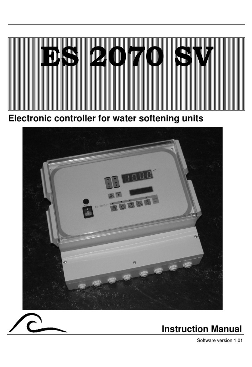
EWS EC3020 User manual

Controller for exchange cylinder systems
EC3020
Instruction manual
Software version 2.00

Contents
General description ………………….………..............................................….. 1
Step “Service Filter 1”, “Standby filter 1”
Step “Service Filter 2”, “Standby filter 2”
Step “No Service”
Step “No Service 1+2”
Step “No Service 2+1”
Value and function display …………..................................................…………. 4
Info display …………………................................................………….…………. 5
Alarm……………………………................................................…………………. 7
CM Min
Power failure
Exchange cylinder 1
Exchange cylinder 2
Exchange cylinder 1+2
Exchange cylinder 2+1
Input functions ……………………….…......................................................…….. 10
Tank empty
Tank full
Alarm reset
Output functions ……...........................................................…….…………..........12
Service valve 1
Service valve 2
Alarm

Changing and calling up basic parameters.............................................……… 13
1. Language
2. Number of filters
3. Conductivity meter
4. Temperature
5. Correction factor
6. Level switches
7. Alarm
Connection diagram……….…………................................................….………… 19
Installation recommendations and commissioning ………..……….…....….… 20
Technical specifications………..……….…….......................................…....….… 22
Declaration of Conformity…..…..…….……............................................…..........23

EC3020 General description
1
General description
The EC3020 controller is used for the fully automatic monitoring and control of
single or duplex cylinders for exchange cylinder systems, whereby the filter
cylinders have to be regularly exchanged.
The basic controller parameters can be changed at any time; the programmed
values are not lost in the event of a power failure.
The controller operates according to 7 steps, indicated as "Service Filter 1",
“Standby Filter 1”, "Service Filter 2", “Standby Filter 2”, “No Service”, “No Service
1+2” and “No Service 2+1”.
The controller checks the conductivity of the water and if this exceeds a settable
limit value, performs the following actions:
- In case of single filter systems, switches to “No Service”.
The Service valve is closed and, once the cylinder is exchanged, the system must
be switched on by hand using the external key.
- In case of duplex systems, switches to the other filter cylinder.
If the engaged filter cylinder, within a programmed period, also produces water with
too high conductivity, the system is switched off.
After replacing the filter cylinders, these can be switched on by hand, using the key
on the outside of the controller.
In single filter systems, the service valves of the cylinder must be connected to
“SV1”.

EC3020 General description
2
Step "Service Filter 1”, “Standby filter 1”
Filter cylinder 1 produces demineralised during “Service filter 1”.
As an option, it is possible to regulate the Service valve by 1 or 2 level switches.
If 1 level switch is set, the Service valve is opened after a delay, which can be
programmed.
If 2 level switches are set, the Service valve is opened after a fixed delay of one
second.
If the filter does not need to produce any water, the Service valve is closed and
“Standby filter 1” appears in the LCD display.
The following values are monitored
- Conductivity under the minimum limit value (only if the Service valve is
opened)
-The maximum conductivity limit value (from version 1.01.02 only if the
service valve is opened).
-Inlet tank low level
-Inlet tank high level
Step "Service Filter 2”, “Standby filter 2”
Filter cylinder 2 produces demineralised during “Service filter 2”.
As an option, it is possible to regulate the service valve by 1 or 2 level switches.
If 1 level switch is set, the service valve is opened after a delay, which can be
programmed.
If 2 level switches are set, the service valve is opened after a fixed delay of one
second.
If the filter does not need to produce any water, the service valve is closed and
“Standby filter 2” appears in the LCD display.

EC3020 General description
3
The following values are monitored
- Conductivity under the minimum limit value (only if the service valve is
opened)
-The maximum conductivity limit value (from version 1.01.02 only if the
service valve is opened).
-Inlet tank low level
-Inlet tank high level
Step "No Service”
This step only appears in single filter systems.
The system is switched off when the filter cylinder is saturated.
Once the filter cylinder is exchanged, it can be switched on by pressing the external
key (press 1x).
Step "No Service 1+2”
If both filter cylinders shortly after one another produce water with too high
conductivity, the system is switched off. Once the filter cylinders are exchanged,
these must be switched on by pressing the external key (press 2x). Filter 1 will in
this case be switched on first.
During this step, conductivity is not monitored and the service valves remain closed.
Step "No Service 2+1”
If both filter cylinders shortly after one another produce water with too high
conductivity, the system is switched off. Once the filter cylinders are exchanged,
these can be switched on by pressing the external key (press 2x). Filter 2 will in
this case be switched on first.
During this step, conductivity is not monitored and the service valves remain closed.

EC3020 Value and function display 4
Value and function display
First LCD line
The current status of the system is shown in the first line of the LCD display:
"Service Filter 1", "Standby filter 1", “Service Filter 2”, “Standby filter 2”,
“No Service 1+2” and “No Service 2+1”.
In case of an alarm situation, an alternating message appears.
Second LCD line
The measured conductivity is shown in the second line of the LCD display.
ATTENTION! If the message "OFL" appears in the second line, the value falls
outside the measurement range.
Example:
Service
F
ilter 1
CM 40.0uS/cm

EC3020 Info display 5
Info display
Various information can be called up by pressing the information key.
Pressing the key again changes the information shown.
Input positions
The current switch positions of the input functions are shown here.
EM = low level switch
FU = high level switch
Output positions
The current switch positions of the outputs SV1, SV2 and AL are shown here.
SV1 = Service valve filter 1
SV2 = Service valve filter 2
AL = Alarm
Input
EM- FU-
Output
SV1- SV2- AL-

EC3020 Info display 6
Software version
The software is regularly updated to ensure that the product complies with the latest
insights and needs.
The number of the operational version is indicated.
Software version
EC3020 1.01.00

EC3020 Alarm 7
Alarm
If the alarm relay is activated, it can be deactivated by pressing the external key.
Although this deactivates the relay, the message is still shown in the LCD display.
Press the key again to remove the message.
CM MIN
The conductivity value of the conductivity meter has dropped below the set
minimum limit value. The system remains operational.
The message in the LCD display can be switched off as soon as the minimum limit
value is again exceeded. The alarm relay can be activated.
Power failure
It is possible to program an alarm in case a power failure occurs while the controller
is operational.
Limit CM Min
under valued
S
ignal
S
upply failure

EC3020 Alarm 8
Exchange cylinder 1
This message appears if filter 1 has produced water with too high conductivity and
the filter cylinder needs to be exchanged.
The message is not programmable and is always transmitted to the alarm relay.
Exchange cylinder 2
This message appears if filter 2 has produced water with too high conductivity and
this filter cylinder needs to be exchanged.
The message is not programmable and is always transmitted to the alarm relay.
Exchange
Cylinder 1
Exchange
Cylinder 2

EC3020 Alarm 9
Exchange cylinder 1 +2
This message appears if both filters shortly after one another produce water with
too high conductivity and the cylinders of these filters need to be exchanged. When
switching on the system by hand, filter 1 will be engaged first.
The message is not programmable and is always transmitted to the alarm relay.
Exchange cylinder 2+1
This message appears if both filters shortly after one another produce water with
too high conductivity and the cylinders of these filters need to be exchanged. When
switching on the system by hand, filter 2 will be engaged first.
The message is not programmable and is always transmitted to the alarm relay.
Exchange
Cylinder 1+2
Exchange
Cylinder 2+1

EC3020 Input functions 10
Input functions
The inputs ‘storage tank empty’ (EM), ‘storage tank full’ (FU) and ‘Alarm reset’
(IN) are included as standard.
Tank full / Tank empty
The input functions ‘Tank full’ (FU) and ‘Tank empty’ (EM) are used for the
automatic filling of a storage tank.
The use of 0, 1 or 2 level switches can be set in step 5.1.
Filling up takes place:
- always if no level switch is connected.
- subject to a programmable delay if one level switch is set.
- subject to a fixed delay of one second if two level switches are set.
The input function FU is active when the contact is open.
The input function EM is active when the contact is closed.
If the storage tank is empty, the contact of both level switches should be closed.
Alarm reset
No further programming possible. The input is connected to the built-in switch on
delivery.

EC3020 Input functions 11
Conductivity probe
The connection for the conductivity probe is indicated by ‘CC’.
The measurement range of the conductivity probe depends on the cell constant.
The cell constant can be programmed in step 2.1.
Also, it is possible to set the minimum and maximum limit values with a
programmable delay time. Whether the alarm relay should be activated in the case
of a specific message can be set in step 9.1.
It is also possible to compensate for the temperature factor in the conductivity
measurement. The water temperature can be programmed in step 3.
Example:
Set/measured water temperature: T = 11 °C
Measured conductivity value: C
11
= 100 μS/cm
Applicable correction factor: K = 1.4
Shown conductivity value: C
25
= 140 μS/cm

EC3020 Output functions 12
Output functions
The outputs ‘Service valve 1’ (IV), ’Service valve 2’ (PU) and ‘Alarm’ (AL) are
included as standard.
Service valve 1
Service valve 1 is opened if the first filter is activated and, possibly dependent on
one or more level switches, demineralised water must be produced.
The maximum current load on this output is 8A (fused).
Service valve 2
Service valve 1 is opened if the second filter is activated and, possibly dependent
on one or more level switches, demineralised water must be produced.
The maximum current load on this output is 8A (fused).
Alarm
The alarm relay can be activated under certain conditions, such as:
- minimum conductivity value exceeded
- power failure
- switch to filter 1
- switch to filter 2
- system switch off
Energizing of the alarm relay in case of a failure can also be programmed.

EC3020 Changing and calling up the basic parameters 13
Changing and calling up the basic parameters
On taking the controller into operation, the operating values of the reverse osmosis
system are set by entering the basic parameters.
These values can be changed at any time, but will not be lost in the event of a
power failure.
To prevent accidental program changes, the key must be pressed for
four seconds before gaining access to the programming mode.
Simply press the same key to navigate the programming mode.
The programming mode is automatically exited approx. 2 minutes after
the last key operation or by entering the indicated key combination.
Press the top key to move the cursor.
Use the bottom key to change numerical values, which you have
selected with the cursor, within the available range.
Also use this key to switch between ‘-‘ and ‘|’ in case of option questions.

EC3020 Changing and calling up the basic parameters 14
1. Language
The language can be set in the step.
2. Number of filters
Enter the number of filters installed in the system.
3. Conductivity meter
A measurement cell with a specific cell constant must be selected depending on the
required conductivity of the water. Here, a cell constant of 0.01 to 10.00 cm
-1
can be
programmed for the conductivity meter.
An electronic interruption of the
measurement cell, electronic defects in the system or air in the measurement cell
Step no.: 1.1
D Nl E F
Step no.: 3.1
Constant 0.10
Step no.: 3.2
Value Min 1.0
Step no.: 2.1
No. of filters 2

EC3020 Changing and calling up the basic parameters 15
can erroneously result in very low conductivity values. For monitoring purposes, a
limit value of 0.0 to 999 μS/cm can be entered.
After a programmed delay time of 1 to 9999 seconds, a drop below the limit value
will result in the error message ‘Value CD Min below the limit value’ being shown in
the LCD display.
A change in the quality of the supply water can lead to change in conductivity. For
monitoring purposes, a limit value of 0.2 to 6500,0 μS/cm can be entered.
If, after a programmed delay time of 1 to 9999 seconds, the maximum conductivity
value is exceeded, the system will switch to the other filter cylinder.
If, after switching to the other filter cylinder, the maximum conductivity is exceeded
within the second programmed delay time, the system will be switched off and can
only be switched on again by hand.
Step no.: 3.3
Delay 60
s
Step no.: 3.4
Value Max 100.0
Step no.: 3.5
Delay 180
s
Step no.: 3.6
Delay2 180
s

EC3020 Changing and calling up the basic parameters 16
4. Temperature
By entering the water temperature, the indicated conductivity value can be
compensated to allow for the current temperature.
The conductivity measurement is based on a water temperature of 25 °C. In case of a
higher or lower temperature, this can be compensated by hand.
5. Compensation correction factor
Other measuring errors, which may arise through valorisation or cable capacities, for
example, can be compensated here by entering a correction factor, varying from 0.10
to 5.0.
Take a water sample and measure the conductivity using an accurate conductivity
meter: this results in the calibration value. Record the controller reading as the
measurement value.
Use the formula below to calculate the correction factor:
Step no.: 4.1
Temperature 25°C
Step no.: 5.1
Factor 1.00*
Correction factor
Measured value
Reference value
=

EC3020 Changing and calling up the basic parameters 17
6. Level switches
Refilling of the storage tank is controlled with the aid of level switches.
Level switch = 1 :
The storage tank is immediately refilled if the level of the water drops below full. A
maximum quantity is always available.
The ‘IN” input can in that case be used as overpressure safeguard.
Level switch = 2 :
An alternative is to use two level switches for refill control. Here, the system is
switched on and when the low level is reached and switched off when the high level
is reached.
Advantage: the system is not switched on and off as often.
The ‘IN” input is used for connecting the low level switch.
The refill delay on the high level switch can be programmed between 1 and 99
seconds.
This step can only be programmed if 1 level switch is set.
Step no.: 6.1
Level switch 1
Step no.: 6.2
Delay FU 4s
Table of contents
Other EWS Controllers manuals
