WATSON INDUSTRIES SPS-P230 User manual

Watson Industries, Inc. SPS-P230 Rev A 10/17/2017
1
STABILIZED PAN AND TILT PLATFORM SYSTEM
OWNER'S MANUAL
PART NUMBER: SPS-P230
WATSON INDUSTRIES, INC.
3035 MELBY STREET
EAU CLAIRE, WI 54703
Phone: (715) 839-0628
FAX: (715) 839-8248
email: support@watson-gyro.com

Watson Industries, Inc. SPS-P230 Rev A 10/17/2017
2
Table Of Contents
Introduction................................................................................................................... 3
Product Description...................................................................................................... 3
Servo System .................................................................................................................................................................4
Joystick Controller.........................................................................................................................................................5
Operation ...................................................................................................................... 5
Start-Up..........................................................................................................................................................................5
Time Constant................................................................................................................................................................5
Pointing Angle...............................................................................................................................................................6
Inertial Mode..............................................................................................................................................................6
Position Mode............................................................................................................................................................7
Error Correction.............................................................................................................................................................7
Centrifugal Force:......................................................................................................................................................7
Delta Velocity (Acceleration):...................................................................................................................................7
Safety Features...............................................................................................................................................................7
Over-current detection:..............................................................................................................................................7
Electronic limit stop:..................................................................................................................................................8
Mechanical limit stop:................................................................................................................................................8
Reverse power connection:........................................................................................................................................8
Installation .................................................................................................................... 8
Mounting:.......................................................................................................................................................................8
Servo System: ............................................................................................................................................................8
User Payload:...........................................................................................................................................................10
Environment: ...............................................................................................................................................................11
Connections: ................................................................................................................................................................11
Power:..........................................................................................................................................................................11
Specifications.............................................................................................................. 12
RS-232 Output Format ............................................................................................... 13
Joystick Controller...................................................................................................... 14
Joystick ........................................................................................................................................................................14
Power Button ...............................................................................................................................................................14
Position Mode Button..................................................................................................................................................14
Home Button................................................................................................................................................................15
Rate Bias Button..........................................................................................................................................................15
Joystick Controller Pinout............................................................................................................................................15
Servo System Pinout....................................................................................................................................................16
RS-232 Input Commands ........................................................................................... 16
Warning ...................................................................................................................... 17
Appendix A................................................................................................................. 19
Appendix B................................................................................................................. 22
Activating Command Mode (Double Spacebar Mode)................................................................................................22
Determining Output Channels .....................................................................................................................................22
Setting Output Channels ..............................................................................................................................................23
Adjust Time Constant ..................................................................................................................................................23
Set Joystick Tilt Axis Parameters ................................................................................................................................24
Set Joystick Pan Axis Parameters................................................................................................................................25
Set New Home Position...............................................................................................................................................26
Set Baud Rate...............................................................................................................................................................27
Watson Industries prides itself on solving customer problems and serving their needs in a timely fashion. This manual
is intended to facilitate this goal and to provide written information about your product. We ask that you carefully read
this manual. Becoming familiar with the manual will help you understand the product’s capabilities and limitations, as
well as provide you with a basic understanding of its operation. If, after reading the manual, you require further
assistance, do not hesitate to call Watson Industries with your questions and comments.

Watson Industries, Inc. SPS-P230 Rev A 10/17/2017
3
CAUTION!
Watson Sensors are rugged devices that have been used successfully in a number of harsh
environments. The components have been qualified to withstand a mechanical shock of 200g 's or
greater, and most enclosures provide an added level of protection. However, dropping a sensor
from waist height onto a hard floor can cause a shock level of 600g's. At this level, damage is
likely to occur.
Introduction
This manual is intended to help in understanding the installation and operation requirements of the
Watson Stabilized Pan & Tilt Platform System. This platform employs gyros to stabilize the
platform to allow devices to be accurately positioned on target irrespective of the motion of the
vehicle on which it is mounted. Details of the operation and adjustments are provided to allow the
owner to obtain optimum performance from this product.
Watson Industries has many years of experience developing stabilized platform sensor packages for
camera and antenna applications. Now we have taken the next step and are offering a complete
system.
Watson Industries also provides custom systems for special requirements. Our system design is
modular and configurable for economical and quick adaptation to a wide variety of hardware
configurations. Watson Industries’ excellent product support and applications engineering goes
along with every product.
Product Description
Watson Industries SPS-P230 Stabilized Pan & Tilt Platform System consists of two components.
The first component is the Servo System and the second component is the Joystick Controller.
These components are connected together by a 5-meter Interface Cable.
Power
Tilt
Pan
owerPosition
Mode
Overcurrent
Pan
Bias
Rate
Home
Tilt

Watson Industries, Inc. SPS-P230 Rev A 10/17/2017
4
Y
Servo System
The Servo System is built around a rugged pan and tilt mechanism. This is a high-resolution digital
system that uses high quality, wide bandwidth, low noise, and solid-state gyros. The whole system
is user configurable to adapt to a wide range of payloads and requirements.
Figure 1 Two-axis gyro Stabilized Platform installation
Each axis uses a servomotor, which drives the platform through an anti-backlash gear, a precision
potentiometer for positional measurements, and a pair of limit stops. The anti-backlash gear
minimizes the backlash from platform motions to less than 10 Arc Seconds. Furthermore, Watson
Industries has installed two gyros and a triaxial accelerometer that are used to calculate corrective
commands to the drive motors.
The two gyros are rugged vibrating-structure gyroscopes, whose angular rate signals are converted
from analog to 16-bit digital form. The effects of temperature variation on the DC bias of the gyros
are digitally corrected.
The micro controller assesses the desired motion of the platform based on joystick commands
received through the RS-422 serial link from the Joystick Controller. It then compares this desired
motion against the real motion of the platform, sensed by the gyros and accelerometers, developing
a rate error value. A servo-control system uses the angular rate and integral of the angular rate to

Watson Industries, Inc. SPS-P230 Rev A 10/17/2017
5
derive a motor voltage that drives the error to zero. In other words, the servo-control system
ensures that the motion of the platform matches that of the joystick commands.
The servo driver module in the mount enclosure accepts commands from the micro controller in
digital form, converts them to pulse-width modulation using two full-bridge switching motor
drivers and then applies the modulated signal to the two motors.
The platform is carefully designed to be rugged and reliable. Particular attention has been paid to
minimizing the effects of noise at every point in the system. This ensures that full advantage can
be taken of the low noise performance of the gyroscopes a highly stable platform.
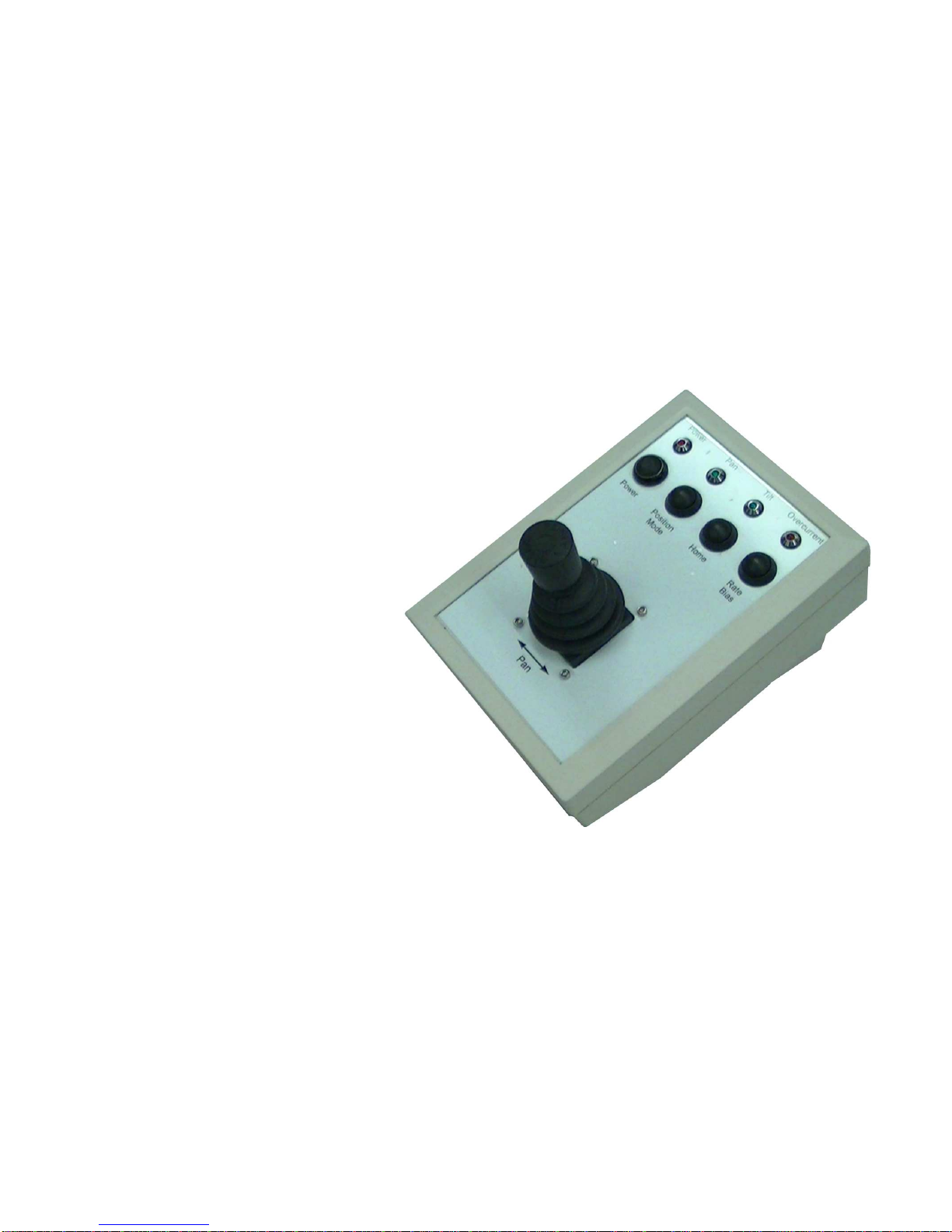
Joystick Controller
The Joystick Controller has a joystick, four buttons, four led indicator lights and three connectors.
The joystick controls the positioning of the SPS-P230 payload. The joystick itself is used to pan
and tilt the payload. The indicator lights and buttons that are used to inform the operator or to
control the operation of the SPS-P230 in different ways.
Operation
Start-Up
The system is automatic. Once power is applied, the stabilized platform system will drive to its
preset home position with any errors corrected by using a short time constant. The time constant of
the corrections is increased in increments until it reaches the full operational time constant. The
initialization mode has a 10 second duration. Please allow a 30 second warm-up before operating
the unit.
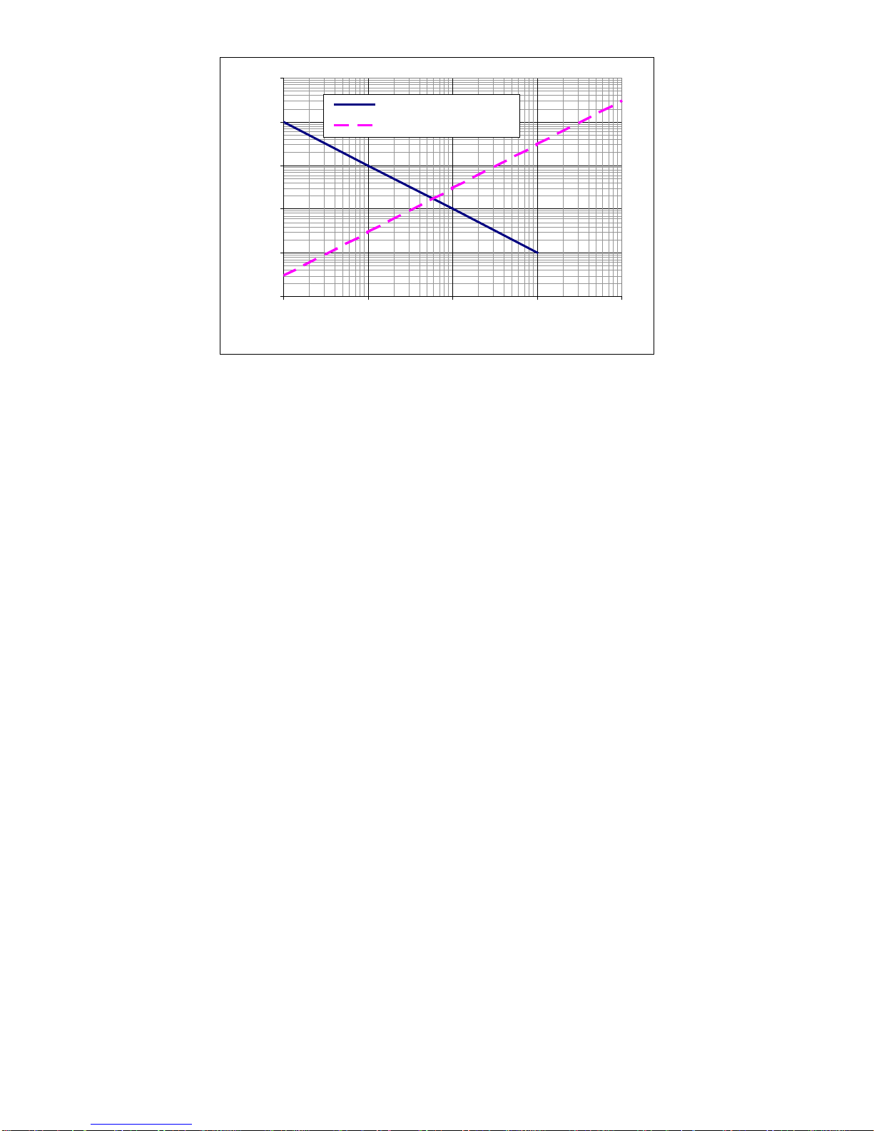
Time Constant
The operational time constant of error correction is chosen for the predicted influences on the
accuracy of the system. Chief among the sources of error are the dynamics of the vehicle and the
drift tendencies of the gyroscopes.
Vehicle dynamics are characterized as being violent when they exist for a short time and gentle
when they are sustained over a long period. They are derivative in nature. In contrast, gyroscopes
have little error in the short term, but these errors grow rapidly as they accumulate in the system.
They are integral in nature. The time constant must be chosen to match the circumstances such that
the least error is likely as shown in example the below:
Watson Industries, Inc. SPS-P230 Rev A 10/17/2017
6
0.01
0.1
1
10
100
1000
1 10 100 1000 10000
Seconds
Error (Degrees)
Dynamic Disturbances
Sensor Drift
Figure 2 Errors versus Time Constant
The correction time constant for this system is adjustable based on the conditions detected by the
system. When increasing errors are detected, the time constant is made longer so that the gyros are
in more control of the angles. This is done on the assumption that short-term errors are more likely
to be caused by vehicle dynamics.
The dynamics of aircraft, ships, or land vehicles all have individual patterns and intensities.
Sometimes, only experience will expose the best time constant setting for the lowest error. This is
why the time constants are settable by the user through the RS-232 connection of the Joystick
Controller. Please consult with Watson Industries before altering the time constants of the unit.
Pointing Angle
In initialization, the unit will drive to a preset “Home” pointing angle based on the potentiometer
reading for each axis. After initialization, the unit can be commanded to return to this pointing
angle by pressing the Home Button on the Joystick Controller. The stable platform will hold this
angle until any joystick motion is detected. Full ranges of offsets to this starting point (within
mechanical limits) are settable by the user through a RS-232 connection of the Joystick Controller
(See Appendix B - Set New Home Position Section).
Inertial Mode
In this mode, the unit will stabilize both the pan and tilt axis of the platform. In “I” mode, the pan
and tilt axis will compensate so that the platform can stay pointed at a specific location regardless
of the motions of the vehicle on which it is mounted. Any joystick commands to move the platform
are relative to its stabilized position. Inertial mode is the default mode at startup for the platform.
When the platform is operating in inertial mode, the LED on the position mode button will not be
illuminated. The user can toggle between Inertial Mode and Position mode by pressing the Position
Mode button on the Joystick Controller.

Watson Industries, Inc. SPS-P230 Rev A 10/17/2017
7
Position Mode
Position or “P” mode is a relative positioning mode. It uses the rate gyros to detect motion on the
pan axis and hold the platform in the last commanded position relative to the vehicle. The tilt axis
operates differently. In Position mode, as well as Inertial Mode, the tilt axis stays stabilized and
will maintain an inertial position irrespective of vehicle motions. Position Mode is activated by
pressing the Position Mode button on the Joystick Controller. When the platform is operating in
position mode, the LED on the position mode button will be illuminated.
Error Correction
Short-term disturbances will not affect the stable mount system, but as these errors become longer
term, joystick commands will become necessary to correct them. Two common sources of long-
term errors for the “P” mode are discussed below.
Centrifugal Force:
The centrifugal force from turns at a significant speed could pull the pointing angle into error over
time, depending on the pointing angle. If this is a problem, setting the system time constant to a
higher time interval may help.
Delta Velocity (Acceleration):
The compensation for forward acceleration is the same as the centrifugal force compensation.
Safety Features
Over-current detection:
There is current sensing for each axis of this system that is connected to the micro controller. If
sustained excessive motor current is detected (i.e. greater than one amp on either axis), the system
will reduce the drive circuit gain by a factor of 4 to reduce the drive current. The gain will be held
low for 2 seconds after the current is below the limit. Since the components of the system are
balanced, the only regular cause of sustained over current is driving against resistance such as an
obstruction. Such a load on the system could cause the motor to burn out and this must be
Vehicle Motion
Vehicle Motion
Position Mode
Inertial Mode

Watson Industries, Inc. SPS-P230 Rev A 10/17/2017
8
prevented. If an obstruction causes an over current state, the obstruction should be identified and
removed. If an overcurrent state is detected, the overcurrent LED on the Joystick Controller will be
illuminated.
Electronic limit stop:
The system tracks the orientation of the mount by reading the potentiometer outputs and will
prevent driving past a preset angle value held in the micro controller’s non-volatile memory.
Driving the mount away from this limit is not inhibited.
Mechanical limit stop:
This is a mechanical limit adjusted to keep the mount from colliding with its structure. It uses
micro switches to turn off the ability to drive further into the stop by interrupting one side of the
motor driver. This is a last line of defense from a system failure, as it is fully independent from the
other safety systems. Driving the mount away from this limit is not inhibited.
Reverse power connection:
Power is diode protected from voltage polarity reversal. Recovery is immediate and without
damage.
Installation
The servo system is mounted with careful alignment and
bolted together. Additionally, the payload (supplied
separately) must be attached to the SPS. The steps for
this process are described below and should be read and
understood before any installation or assembly begins.
WARNING – Do not apply power until the installation
is complete!
Mounting:
Servo System:
The servo system is the part of the SPS that will
stabilize the payload. The servo system consists of the
main servo housing and the payload-mounting arm. The main servo housing has a circular plate
with four M6 threaded holes and four #12 or M6 clearance holes for mounting. Several steps
should be followed for a proper installation of the servo system:
1. The servo system is heavy and must be supported during installation to its mounting place.

Watson Industries, Inc. SPS-P230 Rev A 10/17/2017
9
2. Adjust the position of the mounting ring of the servo system so that the paint mark on the
mounting ring will line up in line with the center position of the intended field of view. The
stop pin on the servo system also needs to be aligned fore of the center position of intended
field of view.

Watson Industries, Inc. SPS-P230 Rev A 10/17/2017
10
3. Loosely attach the servo system to the mounting position using four mounting bolts,
washers and possibly nuts. Use bolts that do not protrude beyond the mounting ring.
4. Once the servo system is aligned, secure the four mounting bolts.
User Payload:
Once the servo system is correctly installed, a payload may be installed on the arm of the servo
system. The SPS has no counterweight and is limited by this load imbalance to a 99 lb (45 Kg)
payload. WARNING – Do not apply power until the installation is complete!

Watson Industries, Inc. SPS-P230 Rev A 10/17/2017
11
Environment:
This product has been surface treated for resistance to salt air and precipitation. This resistance is
limited however, and the system should be kept clean and should be inspected for signs of
corrosion damage regularly.
As in all moving mechanisms there is concern about ice interfering with operation. The system has
internal protection against damage from stalling the motors, but performance may be reduced.
The system should be considered fragile:
DO NOT APPLY LOADS OR FORCES TO THE PAYLOAD.
Connections:
This product has two components. The Servo System and the Joystick Controller Box. First
connect the Servo System and Joystick Controller box together using the 5 meter Interface Cable
The 7 pin connector end of the Interface Cable is attached to the Joystick Controller box and the 8
pin connector end is connected to the Servo System. Make sure the power switch is in the off
position (up – non depressed position). Now the power connection is attached to the Joystick
Controller Box. The mating connector is included. Be sure to use the proper gauge wire for this
connection as the unit can draw up to 6 Amps of current @ 28 VDC. See Joystick Controller
Pinout Section.
The Power Switch on the Joystick Controller Box switches on power to the entire system.
Power:
This unit has an internal regulator to allow operation over a moderate voltage input range. Best
operation is obtained at 28 VDC level, although operation is fully satisfactory down to 18 VDC and
up to 30 VDC. The peak current is about 6 amperes. Internal capacitors are provided to remove a
reasonable level of power line noise, however, capacitors should be added for long power line
wiring or if noise is induced from other loads on the circuit.

Watson Industries, Inc. SPS-P230 Rev A 10/17/2017
12
Specifications
Platform
Range: Pan ±170° (Electronic) ±175° (Mechanical)
Range: Tilt ±90° (Electronic) ±95° (Mechanical)
Slew Rate: Bank, Elevation ±45°/sec
Tilt Accuracy: Static ±1.5°
Tilt Accuracy: Dynamic ±3.0°
Noise: 0.1° rms
Stability: ±1.5° Over 20 minutes
Environmental
Temperature: Operating -20°C to +50°C
Temperature: Storage -50°C to +80°C
Vibration: Operating 0.5 g rms 100 Hz to 1 KHz
Vibration: Survival 2 g rms 100 Hz to 1 KHz
Electrical
Startup Time: Operational 10 seconds
Startup Time: Full Performance 90 seconds
Input Power: 18 to 30 VDC
Input Current: 2A @ 28VDC 6A Peak
Physical
Size: Including Mounting Flanges 6.7"W x 15.8"L x 9.2"H 17.0 x 40.1 x 23.4 (cm)
Weight: 28lb (12.7Kg) Not including payload
Connection: RS-232 9 pin female "D" subminiature On joystick controller
Connection: Power MS3112E-8-4P (4 pin male) On joystick controller
Connection: Interface MS3102A-16S-1S (7 pin female)
MS3102A-20-7P (8 pin male) On joystick controller
On servo controller
Interface Cable: 5 meter MS3106A-16S-1P 7 pin male end
mates to joystick controller MS3106A-20-7S 8 pin female end
mates to servo system
Capacity: 45 Kg
Base Mounting Holes: Qty 8 (4 x M6 threaded; 4 x #12
M6 clearance) 4" dia. bolt circle
Payload Mounting Holes: Qty 8 #12 (M6 clearance) 4" dia. bolt circle
• Specifications are subject to change without notice.
• This product may be subject to export restrictions. Export Classification ECCN EAR99.

Watson Industries, Inc. SPS-P230 Rev A 10/17/2017
13
RS-232 Output Format
The nominal RS-232 output consists of a string of decimal ASCII characters sent asynchronously at
regular intervals at about 10 strings per second. The string is set to be sent at 9600 baud with eight
data bits, one stop bit, no parity, and no handshaking. The factory settings for the contents of the
string is formed as follows:
1. A six character string representing the tilt angle starting with a space, then a “+” or a “-“,
followed by two digits, a decimal point, and one digit for up to ±89.9 degrees.
2. A six character string representing the pan angle starting with a space, then a “+” or a “-“,
followed by three digits, a decimal point, and one digit for up to ±179.9 degrees.
3. A six character string representing the tilt axis angular rate starting with a space, then a “+”
or a “-“, followed by two digits, a decimal point and one digit for up to ±99.9
degrees/second.
4. A six character string representing the pan axis angular rate starting with a space, then a “+”
or a “-“, followed by two digits, a decimal point and one digit for up to ±99.9
degrees/second.
5. A five character string representing the power supply voltage starting with a space,
followed by two digits,
a decimal point, and one digit for up to 35.0 VDC.
6. .A six character string representing the tilt axis motor current starting with a space, then a
“+” or a “-“, followed by one digit, a decimal point and two digits for up to ±9.99 Amps.
7. A six character string representing the pan axis motor current starting with a space, then a
“+” or a “-“, followed by one digit, a decimal point and two digits for up to ±9.99 Amp.
8. A four character string representing the Status Bits starting with a space, followed by three
ASCII characters representing Octal digits.
9. A seven character string representing the Flag Bits starting with a space, followed by two
ASCII characters (Flag Bits1) representing Octal digits, a space, followed by three ASCII
characters (Flag Bits2) representing Octal digits.
10. The string is terminated by a carriage return. There will then be a short interval with no data
transmission before the next string begins.
Example:
+02.5
-001.5 +02.5 -05.0 24.5 +0.25 -0.22 064 04 000 <CR>
Tilt
Angle
(1)
Pan.
Angle
(2)
Tilt
Rate
(3
Pan
Rate
(4)
Power
Supply
Voltage
(5)
Tilt
Current
(6)
Pan
Current
(7)
Status
Bits
(8)
Flag
Bits
(9)
(10)
↑
↑
↑
↑
↑
↑
↑
↑
space space space
space space space space space
Watson Industries, Inc. SPS-P230 Rev A 10/17/2017
14
The output message and baud rate can be configured by the user. See Appendix B for more
information.
A text header is sent by the SPS during initialization that identifies the unit by part number and
serial number and gives the date of last calibration. Additionally, a line of text characters that
identifies the data channel columns is sent if the serial output is set to ASCII decimal. This header
message can be suppressed or restored by sending a “*” command from the interfacing computer.
This change can also be made the default by sending a quote (“) command.
Data transmission sent by the SPS-P230 can also be suppressed or restored by sending a “+”
command from the interfacing computer. This change can be made the default setting by sending a
quote (“) command.
Joystick Controller
The Joystick Controller has a
joystick, four buttons, four led
indicator lights and three
connectors. These items are
explained below.
Joystick
The joystick positions the SPS-P230
payload. A left or right movement
of the joystick controls the pan
motion of the payload while an up
or down movement controls the tilt.
The joystick is also used to correct
any rate bias in the system, which is
discussed later. When the joystick
is commanding the SPS-P230 to
move in the pan axis, the green pan
indicator light will be illuminated.
Similarly, when the system is
moving in the tilt axis, the green tilt
indicator light will be illuminated.
Power Button
The power button turns the SPS-P230 on and off. When the system is powered on, the power
indicator light will be illuminated.
Position Mode Button
This button toggles the sensor between position mode and inertial modes of operation. When the
platform is operating in position mode, the LED on the position mode button will be illuminated.
For more information on these to modes, see the Pointing Angle section earlier in this manual.

Watson Industries, Inc. SPS-P230 Rev A 10/17/2017
15
Home Button
Pressing the home button will command the SPS-P230 to return the payload to a predetermined
Home position. The platform will stay at this position regardless of vehicle motion. Any joystick
input will exit the home position. The home position is set through the SPS-P230 menu system. See
Appendix B for more information.
Note: When the SPS-P230 is first powered on, it will go to the home position.
Rate Bias Button
The rate bias button allows the user to eliminate any rate bias motion from the platform using
joystick inputs. Pressing this button toggles the sensor between normal operation and a special rate
bias adjustment mode. When the SPS-P230 is in rate bias adjustment mode, the LED on the rate
bias button will be illuminated. When in this mode, joystick motions are added to the system as
bias adjustments. Moving the joystick in the pan axis will adjust pan rate bias, while joystick tilt
motions will adjust tilt rate bias.
Joystick Controller Pinout
The joystick controller has three connectors mounted to the rear panel as shown below:
9 Pin Female D-Sub
RS-232 Interface MS3102A-16-1S
Interface to Platform MS3112E-8-4P
Power
Pin Description Pin
Description Pin
Description
1 N.C. A Power Ground A N.C.
2 RS-232 TXD B +28VDC Power B +28 VDC Power In
3 RS-232 RXD C RS-422 RX+ C N.C.
4 N.C. D RS-422 RX- D Power Ground
5 Signal Ground E Signal Ground
6 N.C. F RS-422 TX-
7 N.C. G RS-422 TX+
8 N.C.
9 N.C.
12345
69 8 7
A
B
C D
G
F
E
A
B C
D

Watson Industries, Inc. SPS-P230 Rev A 10/17/2017
16
Servo System Pinout
The Servo System has one connector:
Pin Function
A Power Return
B +28 Volt Power
C RS-422 TX+
D RS-422 TX-
E Signal Ground (connected internally to Power Return)
F RS-422 RX-
G RS-422 RX+
H Case Ground
RS-232 Input Commands
The RS-232 input commands are provided for the purpose of unit test and installation set-up.
These input commands use the same communication parameters that the output data uses (9600
baud ASCII nominal, or as reset in the units EEPROM). There are some commands intended for
the user while others are used at the factory for alignment and calibration.
An exclamation point “!” will reinitialize the unit just as re-powering the unit would. Furthermore,
the access to initialization is inhibited such that a spacebar command must be sent within 2.5
seconds of the “!” command for initialization to be engaged.
There are several interface commands: “:” will toggle the output to send a frame of data upon
receiving any non-command character and “+” will toggle the output for no output data. These
and other changes are made non-volatile (default) in the unit on EEPROM by keying in the quote
(“) character. Double spacebar at initialization is required for access to these commands.
Note that the “:” setting will cause the mechanical brake to be engaged between frames. This is not
intended to be an operational mode.
The “&” command calls a menu which allows any of several parameters to be set. These are the
system time constant, joystick/axis parameters, selection of data channels for serial output, listing
current serial channels and baud rate. Double spacebar at initialization is required for access to this
command. See Appendix B for more information.
The commands “~”, “@”, “#”, “$”, “(“, “)”, “{“, “}”, “|”, “<”, “>” and “?” are used by the Watson
factory to calibrate the unit and should be used only with the assistance of the factory. If an
undesired function is called, a “Q”, and sometimes the Escape or Delete key will interrupt the
command and return to operation with the least disturbance to the system. All other unspecified
characters such as carriage return, line feed and space are ignored by the system.
}
Transmit from SPS-P230
}
Receive to Joystick Controller

Watson Industries, Inc. SPS-P230 Rev A 10/17/2017
17
Warning
Rough handling or dropping of this unit is likely to cause damage.
Over-voltage and/or miswiring of this unit will cause damage.
This unit should be inspected regularly when exposed to
prolonged exposure to high humidity and/or salt air environments.
DISCLAIMER
The information contained in this manual is believed to be accurate and reliable; however, it is the
user’s responsibility to test and to determine whether a Watson Industries’ product is suitable for a
particular use. Suggestion of uses should not be taken as inducements to infringe upon any patents.
This product is not to be used as a primary instrument for life critical use.
WARRANTY
Watson Industries, Inc. warrants, to the original purchaser, this product to be free from defective
material or workmanship for a period of two full years from the date of purchase. Watson
Industries’ liability under this warranty is limited to repairing or replacing, at Watson Industries’
sole discretion, the defective product when returned to the factory, shipping charges prepaid, within
two full years from the date of purchase. All sensors returned under warranty will be repaired (or
replaced at the sole option of Watson Industries) at no cost to the customer other than shipping
charge from customer to Watson Industries (plus any export and transportation charges outside the
United States). The warranty described in this paragraph shall be in lieu of any other warranty,
express or implied, including but not limited to any implied warranty of merchantability or fitness
for a particular purpose.
Excluded from any warranty given by Watson Industries are products that have been subject to
abuse, misuse, damage or accident; that have been connected, installed or adjusted contrary to the
instructions furnished by seller; or that have been repaired by persons not authorized by Watson
Industries.
Watson Industries reserves the right to discontinue models, to change specifications, price or
design of this product at any time without notice and without incurring any obligation whatsoever.
The purchaser agrees to assume all liabilities for any damages and/or bodily injury, which may
result from the use, or misuse, of this product by the purchaser, his employees or agents. The
purchaser further agrees that seller shall not be liable in any way for consequential damages
resulting from the use of this product.
No agent or representative of Watson Industries is authorized to assume, and Watson Industries
will not be bound by any other obligation or representation made in connection with the sale and/or
purchase of this product.
PRODUCT LIFE
The maximum expected life of this product, other than wear out, is 20 years from the date of
purchase. Watson Industries, Inc. recommends the replacement of any product that has exceeded
the product life expectation.

Watson Industries, Inc. SPS-P230 Rev A 10/17/2017
18
Customer Service
All repairs, calibrations and upgrades are performed at the factory. Before returning any product,
please contact Watson Industries to obtain a Returned Material Authorization number (RMA).
Return Address & Contact Information
Watson Industries, Inc.
3035 Melby Street
Eau Claire, WI 54703
ATTN: Service Department
Returning the Product
Product shall be packaged making sure there is adequate packing around all sides. Correspondence shall
include:
• Customer’s Name and Address
• Contact Information
• Equipment Model Number
• Equipment Serial Number
• Description of Fault
It is the customer’s responsibility to pay all shipping charges from customer to Watson
Industries, including import and transportation charges.

Watson Industries, Inc. SPS-P230 Rev A 10/17/2017
19
Appendix A
The following outputs are available via the RS-232 serial link. Their full-scale ranges are listed for decimal format.
Inertial Output Label Decimal Range
Time TM 000.1 to 999.9 s
Tilt Angle TA ±89.9º
Pan Angle PA ±179.9º
X Accelerometer XA ±9.99 g
Y Accelerometer YA ±9.99 g
Z Accelerometer ZA ±9.99 g
Tilt Axis Angular Rate TR ±99.9 º/s
Pan Axis Angular Rate PR ±99.9 º/s
Power Supply Voltage PS 00.0 to 35.0 VDC
Tilt Potentiometer PT ±179.9º
Pan Potentiometer PP ±179.9º
Tilt Current TC ±9.99 Amps
Pan Current PC ±9.99 Amps
Tilt Joystick Rate TJ ±49.9 º/s
Pan Joystick Rate PJ ±49.9 º/s
Temperature TP -40º to 88ºC
Status Bits ST 3 ASCII chars representing
Octal digits
Flag Bits 1 F1 2 ASCII chars representing
Octal digits
Flag Bits 2 F2 3 ASCII chars representing
Octal digits
Status Bits:
The status bits provide operational information that is presented as two ASCII octal digits. The
first digit is made up of one bit as follows:
First Digit Mode
1 Position
0 Inertial
The Second digit is made from three bits as follows:
1) Initialization mode equals a value of 1 during start up.
2) Tilt Error Flag equals 1 when Tilt angle is in error
3) Pan Error Flag equals 1 when Pan Angle is in error
Second Digit Pan Error Tilt Error Initialization
7 Yes Yes Yes 4 + 2 + 1
6 Yes Yes No 4 + 2
5 Yes No Yes 4 + 1
“4” Pan Error
4 Yes No No 4
“2” Tilt Error
3 No Yes Yes
2 + 1 “1” In Initialization
2 No Yes No 2
1 No No Yes 1
0 No No No

Watson Industries, Inc. SPS-P230 Rev A 10/17/2017
20
The Third digit represents the current time constant as a power of two:
TC = 2
X
Seconds
The nominal time constant is 64 seconds which would display the octal value of X as “6”.
Third
Digit Time Constant
(seconds)
7 128
6 64
5 32
4 16
3 8
2 4
1 2
0 1
Flag Bits 1:
The flag bits present warning information. The first digit is made from three bits:
1) Pan angle negative stop limit equals a value of 1 when the Pan potentiometer reaches a
preset limit.
2) Pan angle positive stop limit equals a value of 2 when the Pan potentiometer reaches a
preset limit.
3) Pan axis active bit equals a value of 4 when the Pan axis is active.
First
Digit Pan Axis
Active Pan Angle Positive
Stop Limit Pan Angle Negative
Stop Limit
6 Yes Yes No 4 + 2
5 Yes No Yes 4 + 1
“4” Pan Axis Active
4 Yes No No 4
“2” Pan Positive Stop Limit
2 No Yes No 2
“1” Pan Negative Stop Limit
1 No No Yes 1
The second digit is made from three bits as follows:
1) Tilt angle negative stop limit equals a value of 1 when the Tilt potentiometer reaches a
preset limit.
2) Tilt angle positive stop limit equals a value of 2 when the Tilt potentiometer reaches a
preset limit.
3) Tilt Axis active bit equals a value of 4 when the Tilt axis is active.
First
Digit Tilt Axis
Active Tilt Angle Positive
Stop Limit Tilt Angle Negative
Stop Limit
6 Yes Yes No 4 + 2
5 Yes No Yes 4 + 1
“4” Tilt Axis Active
4 Yes No No 4
“2” Tilt Positive Stop Limit
2 No Yes No 2
“1” Tilt Negative Stop Limit
1 No No Yes 1
Table of contents
Other WATSON INDUSTRIES Industrial Equipment manuals


