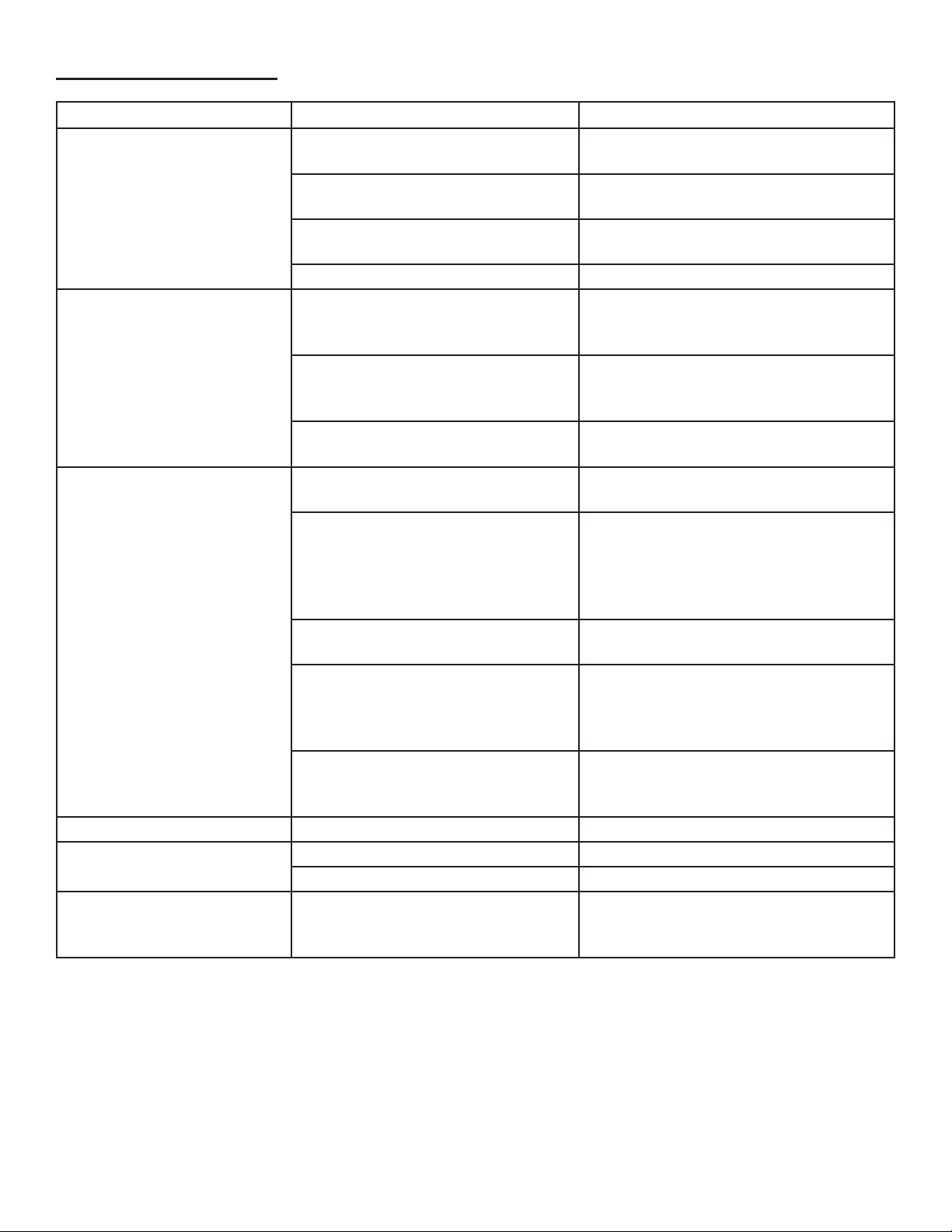
Formax FD 87HD User manual

FD 87HD
Hard Drive Punch
MAINTENANCE MANUAL
FIRST EDITION
2/2014

TABLE OF CONTENTS
TOPIC PAGE
Specications 1
Set-up Guidelines 1
Operation 2
Safety Devices & Other Features 2
Safety Precautions 3
Daily Maintenance 3
Troubleshooting 4 - 7
Parts Lists 8 - 12

1
Set-up Guidelines
1. Install the FD 87HD on a level surface, away from heat sources and direct sunlight.
2. Insert plug into wall outlet with the appropriate voltage, 110V. If the outlet is shared with another electronic
device, the total current should not exceed 30A (at 110V).
Specications
Punch Hole Size: .39” (10mm)
Hard Drive Size: 2 1/2” or 3 1/2”
Feed Opening: 4.65” (118mm)
Punching Cycle: 14 seconds
Dimensions: 19.68” W x 18.5” D x 35” H (500 x 470 x 890mm)
Weight: 154 lbs. (70kg)
Security Level: H-3 (DIN 66399 standard)
Power Supply: 110V, 50-60Hz
LED Control Panel
Door (waste bin inside)
Safety Shield
Safety Shield HandleRelease Knob
Power Switch
Punching Chamber
Start: Punch is operating
AutoReverse: In case of jam, motor automatically switches to reverse to protect the punching die
AutoStop: Automatically stops after each punching cycle
Door Open Sensor: If the waste bin door or safety shield are open, LED will light and operation will stop
Waste Bin Full: If the waste bin is full, LED will light and operation will stop
Fault Indicator: If there is a jam or other fault, LED will light and operation will stop

2
Operation
1. Flip the power switch “ON”, located on the right side of the
machine.
2. Slide open the safety shield on the top of the cabinet (Fig.
1).
3. Insert a hard drive into the punching chamber (Fig. 2).
4. Slide the safety shield closed.
5. Press the green START button on the control panel (Fig.
3). The punching chamber will be illuminated by LED,
and the punching die will puncture the hard drive. After a
brief pause, the die will reverse direction. Once this has
happened and the light goes out, the process is complete.
6. Press the release button (Fig. 4) and the punctured hard
drive will drop into the waste bin (Fig. 5).
Fig. 2
Fig. 3
Fig. 1
Fig. 4
Fig. 5

3
Safety Precautions
To avoid personal injury, and damage to the machine, observe the following safety precautions. Please keep
these instructions for future reference.
NOTE: In case of emergency, push the ON/OFF button on the right side, or pull the plug out of the wall outlet.
Daily Maintenance
• Keep hands, long hair, clothing, ties, jewelry and loose items away from the
punching chamber.
• Do not use the hard drive punch for anything other than its intended purpose.
• Do not allow children to use the machine.
• Do not operate with a damaged power cord or plug, or when the machine is
damaged in any manner.
• Unplug the hard drive punch when it is being moved, or if it is not in use for
an extended period of time.
• Do not disconnect the power by pulling only the cord. Hold the plug when
disconnecting.
• Keep the machine away from direct sunlight.
• Do not sit on the machine or place anything on top of it.
• Never open the xed switch or cover.
Safety Devices and Other Features
The FD 87HD is equipped with various safety features:
Automatic Reverse
If the hard drive cannot be punched, the motor will automatically switch into reverse to prevent damage to the
punching die.
Door Open / Safety Shield Open
If the door or safety shield is open, the machine will not operate. Close the door or safety shield and press start
to resume punching.
Waste Bin Full
When the waste bin is full of punched hard drives, a weight sensor will activate the “FULL” light on the control
panel. Open the door, remove the waste bin and empty it. Replace the waste bin, close the door and continue
operation.
• Disconnect power by pulling power cord plug from wall outlet.
• To clean the exterior, wipe the surface with a soft cloth. If the surface is very dirty, use a neutral detergent,
then wipe again with a soft cloth.
CAUTION:
• Never put water directly on the surface of the machine.
• Never clean the case with benzene or thinner, since it will cause discoloration.
• Do not dismantle the machine. Contact your Formax Dealer for service.

4
TROUBLESHOOTING
PROBLEM: CHECK THIS: SOLUTION:
Hard drive punch will not
operate
Check that the power cord is
plugged into an appropriate outlet
Plug cord into outlet
Check voltage of power outlet
(120VAC, 60Hz)
If necessary, nd an alternate outlet
with the appropriate voltage
Check the wiring between the fuse
connector on the PCB (page 9)
Reconnect, if necessary
Check relay switch on Main PCB Reconnect, if necessary
Main power is functioning but
hard drive punch won’t oper-
ate (Main PCB)
Check main power cable to see if it
is properly connected to the Main
PCB (page 9)
Reconnect, if necessary
Check the Main PCB’s printed
circuit and wire disconnection of
transformer
If there is a problem with the circuit and/
or transformer, replace with new one
Check the electrical contacts on the
main control switch
Reconnect, if necessary
Main power is okay, but hard
drive punch is not working
(electrical)
NOTE: Photo sensor should
be connected with the main
PCB during testing.
Check the outlet for correct voltage,
120V
Use different outlet, if necessary
Check wire connection between
photo sensor and Main PCB (page
9). If there is no output signal from
Main PCB, hard drive punch will not
operate.
Reconnect cable to sensor and Main
PCB
Photo sensor could be dirty Remove photo sensor (page __) and
clean it with a soft cloth
Photo sensor sensitivity may need
to be reset
Sensitivity measurement distance
should be .4 inch (10mm). If distance
is less than .4 inch, replace the photo
sensor
Check power relay contacts Reconnect, or replace main PCB power
relay if necessary. If printed circuit is
damaged, replace the main PCB.
Full light will not go off Check waste bin to see if it’s full Empty waste bin
Door Open light will not go
off
Check cabinet door Close door
Check safety shield Close safety shield
Punching die is not moving
properly
Remove cover, check limit switches
to see if they’re properly connected
to the power board
Reconnect switches, if necessary

5
Start condenser
Running condenser
Motor start relay
Reduction chain
If the motor doesn’t work, check wiring connections to be sure they’re attached properly. Check connections
between motor and the following: start condenser, motor start relay and running condenser.
Troubleshooting Motor Issues
Feed slot
Front spring
Rear spring
Troubleshooting Feed Slot
If the feed slot does not adjust to t both hard drive sizes (2.5” and 3.5”), one or both of the xed springs may
be damaged or broken. Replace the broken spring(s).
Motor
Troubleshooting Feed Chamber Trap Door
If the feed chamber trap door does not operate (releasing the punch hard drive into the waste bin), the trap
door springs may be damaged or broken. Replace the broken spring(s).
Front springs Rear springs

6
If the motor continues to run without punching, the drive screw mounting bracket may be loose or broken, due
to a damaged limit switch. Check the bracket to see if it is loose or broken, and tighten or replace if necessary.
Check the limit switches for proper operation and connection to the Main PCB. Reconnect or replace if
necessary.
Adjusting Drive Screw Mounting Bracket & Limit Switches
Screw xing bracket Limit switches
If the motor continues to run without punching, the motor chain may
be loose or broken. Check the rotation and condition of the chain and
sprockets. Replace if necessary. Grease chain if needed.
Replacing the Motor Chain
Motor chain
If the Bin Full LED does not light even if the waste bin is full, the full switch may be damaged, or there may be
something jammed under it. Remove the waste bin and swing out the waste bin platform on its front hinge.
Remove any foreign objects from under the switch. Check the switch wiring connections to the Main PCB.
Replace the switch if it is damaged.
Cleaning/Replacing the Waste Bin Full Switch
Waste bin full limit switch
Front hinge
Full plate
spring

7
If the door is separated from the body housing, replace the upper and/or lower hinges. If the casters are
damaged, remove screws and attach new casters with screw bolts.
Replacing Door Hinges & Casters
Top hinge
Bottom hinge
Caster screws
Reverse button
Stop button
Start button
Control Panel PCB
Main PCB
Main relay Waste bin full & door openVariable resistance
Display LED connector
Main IC
LED lamp (green)
Punch limit switch
Transformer 2
Transformer 1
Main Connector

8
PARTS LIST - CASE
Other manuals for FD 87HD
1
Table of contents
Other Formax Industrial Equipment manuals


