Ecosoft MO-1 User manual
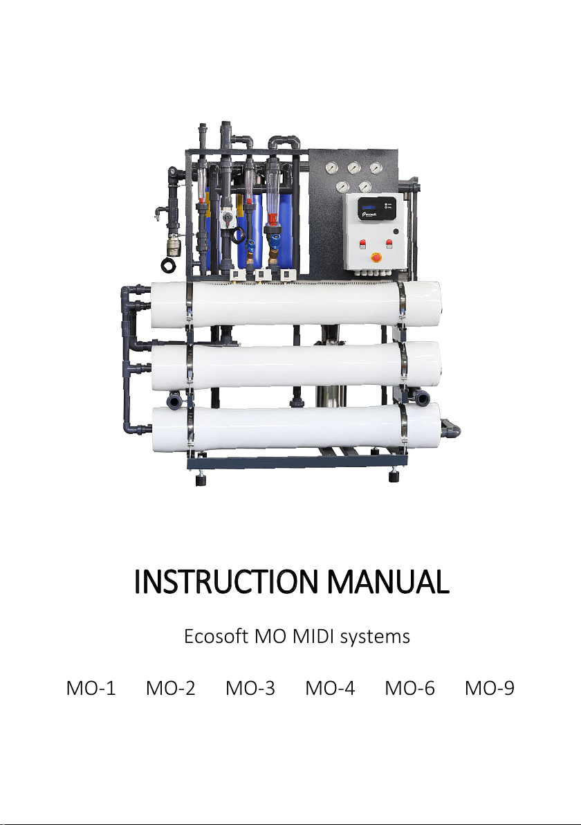
MO-1
MO-2
MO-3
MO-4
MO-6
MO-9
INSTRUCTION MANUAL
Ecosoft MO MIDI systems

C
CO
ON
NT
TE
EN
NT
TS
S:
:
Acronyms and abbreviations 40
RO system 40
1.Overview 40
2. Technical data 41
3. Installation and startup 43
4. Installation requirements 48
5. Operating requirements 49
6. Shipping and storage requirements 52
7. Troubleshooting 53
CONTROLLER 55
1. Overview 55
2. Technical data 56
3. Operating modes 58
4. Program 62
Annex A. Bypass valve P&IDs 67
Annex B. Operation record 68
This appliance is not intended for use by persons
(including children) with reduced physical, sensory
or mental capabilities, or lack of experience and
knowledge, unless they have been given supervision or
instruction concerning use of the appliance by a person
responsible for their safety. Children should be supervised to
ensure that they do not play with the appliance.

40
A
AC
CR
RO
ON
NY
YM
MS
S
A
AN
ND
D
A
AB
BB
BR
RE
EV
VI
IA
AT
TI
IO
ON
NS
S
CIP Clean-in-place
NC Normally closed
RO Reverse osmosis
FF Forward flush
NO Normally open
TDS Total dissolved solids
GPM Gallon per minute
P&ID Piping and instrumentation diagram
LPMLiter per minute
PCB Printed circuit board
R
RO
O
S
SY
YS
ST
TE
EM
M
1Overview
Ecosoft industrial reverse osmosis systems are used for demi-
neralizing water in industrial, municipal, commercial applications.
Ecosoft RO system can be used to demineralize low to medium salinity
feed water. All parts of the system that are in contact with water have
the necessary certifications for use in food/drinking water applications.
Reverse osmosis system operates as follows. First, raw water is
fed through sediment prefilters to remove particles. The water may
be dosed with antiscalant or other RO chemicals with a dosing pump
at this point. Then, high pressure pump feeds the water into the
membrane module or membrane array, in which feed stream
undergoes separation process and splits into purified and
concentrated streams. Part of the concentrated stream is discharged
to drain, and the rest is fed back to suction end of the high pressure
pump, referred to as concentrate recycle. Drain line is fitted with
drain flow control that limits rate of concentrate discharge and
determines the ratio of purified water (permeate) to waste water
(concentrate). The ratio is called recovery. Recycle line is fitted with
recycle flow control that limits recycle flow rate and creates working
pressure in the membrane array. Rate of permeate production is
proportional to the pressure in the membrane modules.
Commissioning and configuring the RO system includes carefully
adjusting the flow controls to the right settings.

41
Improperly commissioned RO system may fail in the
matter of minutes, including irreparable membrane
failure, hardware failure, and also involves electrical and
pressure hazard. Drain flow rate and recycle flow rates should only
be configured by authorized staff.
Permeate stream comes out via permeate outlet and runs to
permeate tank. Purification process will stop whenever the tank is
full of water (signaled by the float switch) or when any backpressure
in permeate line appears, indicating critical condition. The process
will automatically resume when the full tank signal deactivates.
The system is operated with a process controller, which powers
pump(s) and valves so as to carry out service or membrane rinse in the
necessary times. The controller reads signals from pressure switches,
float switch, permeate conductivity and temperature, and external
inhibition. Depending on these signals, it chooses to run in service, rinse
membranes, go to standby, or go to fault mode. Permeate conductivity
and temperature data are displayed to the operator. Depending on
system model, it can be additionally equipped with:
–antiscalant/chemical dosing pumps
–additional electric valve for raw water mixing or membrane
permeate rinsing (see Annex A)
R
RO
O
S
SY
YS
ST
TE
EM
M
2Technical data
Tap feed water must be pre-filtered from fine particulates
and residual chlorine before entering the RO system. Well
water may contain impurities such as hardness, iron,
manganese, silica, hydrogen sulfide that can quickly lead to membrane
failure. Some of these challenges can be addressed by using injection of
antiscalant. Perform a detailed laboratory analysis of your well water
and consult a water treatment specialist to see if you need additional
equipment for treating your well water.
42
MO-9
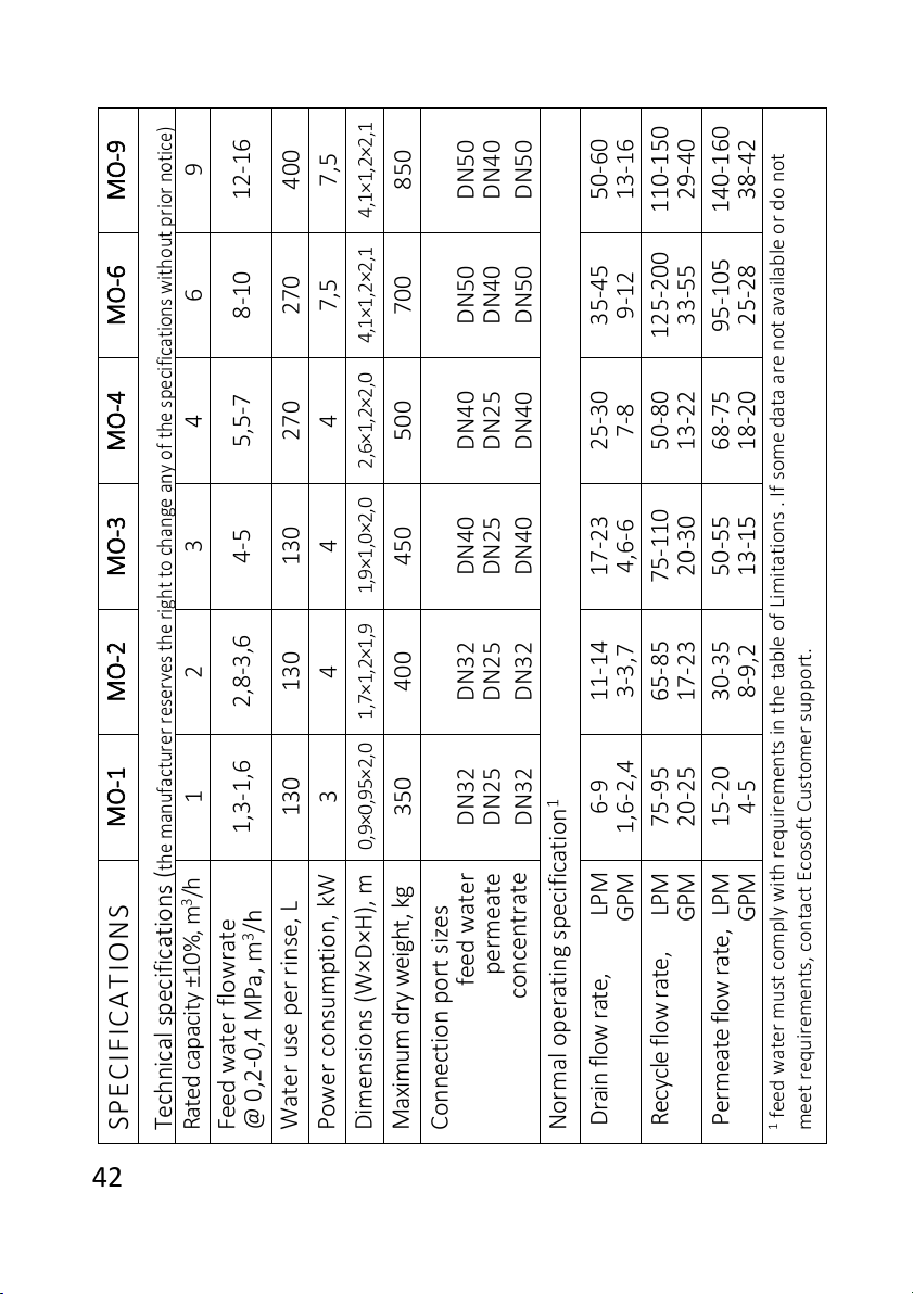
Technical specifications (
the manufacturer reserves the right to change any of the specifications without prior notice)
9
-12 16
400
7,5
4,1×1,2×2,1
850
DN50
DN40
DN50
Normal operating specification1
-50 60
-13 16
-
110-150
29 40
-
140-160
38 42
1feed water must comply with requirements in the table of Limitations . If some data are not available or do not
meet requirements, contact Ecosoft Customer support.
MO-6
6
-8 10
270
7,5
4,1×1,2×2,1
700
DN50
DN40
DN50
-35 45
-9 12
-
125-200
33 55
-
-
95 105
25 28
MO-4
4
5,5-7
270
4
2,6×1,2×2,0
500
DN40
DN25
DN40
-
-
25 30
7 8
-50 80
-13 22
-68 75
-18 20
MO-3
3
-4 5
130
4
1,9×1,0×2,0
450
DN40
DN25
DN40
17-23
4,6-6
-
-
75 110
20 30
-50 55
-13 15
MO-2
2
2,8-3,6
130
4
1,7×1,2×1,9
400
DN32
DN25
DN32
-11 14
-3 3,7
-65 85
-17 23
-30 35
-8 9,2
MO-1
1
1,3-1,6
130
3
0,9×0,95×2,0
350
DN32
DN25
DN32
-6 9
1,6-2,4
-75 95
-20 25
-
-
15 20
4 5
SPECIFICATIONS
Rated capacity ±10%, m3/h
Feed water flowrate
@ 0,2-0,4 MPa, m3/h
Water use per rinse, L
Power consumption, kW
Dimensions (W×D×H), m
Maximum dry weight, kg
Connection port sizes
feed water
permeate
concentrate
Drain flow rate, LPM
GPM
Recycle flow rate, LPM
GPM
Permeate flow rate, LPM
GPM
43
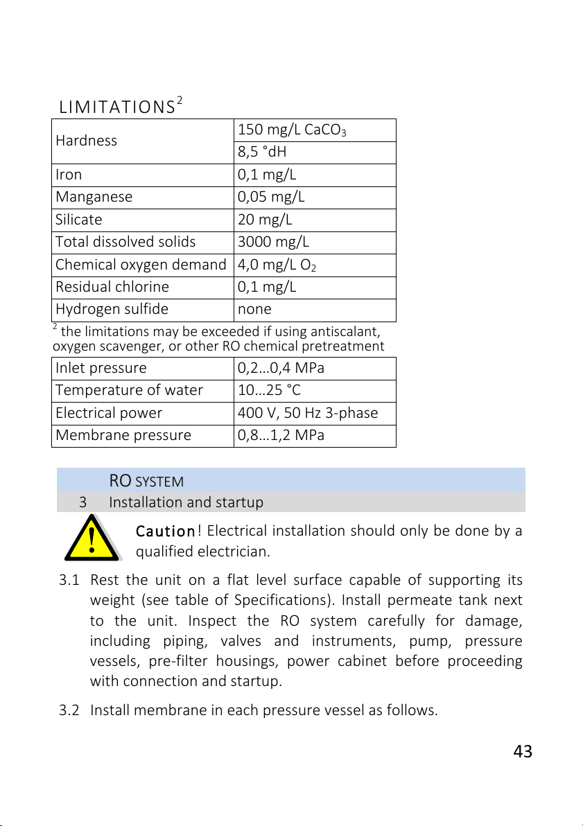
LIMITATIONS2
Hardness
150 mg/L CaCO3
8,5 °dH
Iron
0,1 mg/L
Manganese
0,05 mg/L
Silicate
20 mg/L
Total dissolved solids
3000 mg/L
Chemical oxygen demand
4,0 mg/L O2
Residual chlorine
0,1 mg/L
Hydrogen sulfide
none
2the limitations may be exceeded if using antiscalant,
oxygen scavenger, or other RO chemical pretreatment
Inlet pressure
0,2…0,4 MPa
Temperature of water
10…25 °C
Electrical power
400 V, 50 Hz 3-phase
Membrane pressure
0,8…1,2 MPa
R
RO
O
S
SY
YS
ST
TE
EM
M
3Installation and startup
Caution! Electrical installation should only be done by a
qualified electrician.
3.1 Rest the unit on a flat level surface capable of supporting its
weight (see table of Specifications). Install permeate tank next
to the unit. Inspect the RO system carefully for damage,
including piping, valves and instruments, pump, pressure
vessels, pre-filter housings, power cabinet before proceeding
with connection and startup.
3.2 Install membrane in each pressure vessel as follows.

44
Remove PVC piping with the pressure vessel ports. To remove
PVC pipes, take apart pipe unions at the pressure vessel ports. If
necessary, also loosen next closest downstream union to
remove the entire piping fragment leading to the vessel.
Remove the lid at the feed end of pressure vessel. First, remove
spiral retaining ring by pulling bent tab towards the center of
circle. If the pressure vessel lid is retained by half rims, remove
the fastening screws and pull half rims out of circular groove.
Take out the lid with membrane adapter.
Observe direction of arrow on pressure vessel when
installing membrane. Use glycerol or a similar RO-
compatible lubricant as needed. Avoid touching
membrane with hands. Use sterile rubber gloves when handling
membrane.
Make a cut in membrane packaging bag and insert membrane in
the pressure vessel brine seal last. Central tube of the
membrane has to mate with membrane adapter installed at the
concentrate end of pressure vessel. If necessary, remove the lid
at the concentrate end before installing the membrane.
If installing multiple membranes in one vessel, proceed with the
next membrane in a similar fashion, after installing membrane
connector in central tube of first membrane’s rear end. Couple
the second membrane with the connector, then push it forward
all the way in the pressure vessel.
After the membrane(s) are installed in the pressure vessel,
install the lid back in place. Put spiral retaining ring (or half rims)
in the groove, fasten half rims with screws. Re-assemble the RO
system in reverse order.
3.3 Connect raw water pipe from water main/pump to the entry
solenoid of the RO system. Recommended pipe size is at least
that of the connection port, plastic/composite pipe or rigid non-
kinking hose. Use appropriate fittings as necessary. Connect

45
drain tube or hose with drain outlet of the RO system and run it
to drain pipe. Ensure air gap at the end of drain line to prevent
backsiphonage. Connect tube or hose to permeate outlet and
extend it to permeate tank. Cut or bore an aperture at the top
of tank wall, install pipe gland and pull the permeate tube
through the gland (note: run permeate line to drain when
carrying out initial membrane rinse).
It is strongly recommended to use short runs of pipe or
hose the size of which matches or exceeds that of the
connection port.
3.4 Put the float switch inside permeate tank after moving ballast
the necessary length up the cord to provide enough level
difference between activated and deactivated position. After the
first filling of the tank, verify that the float switch activates and
deactivates in the right positions.
3.5 If the RO system has permeate rinse enabled, install the
necessary piping. If using service interruption by external signal
(microswitch), remove conductor connecting terminals 6 and 7
together on controller PCB. Then, run wire from microswitch
inside the controller housing and connect to the terminals. If
using antiscalant or other RO chemicals, refer to dosing pump’s
instruction booklet for information concerning the dosing pump.
3.6 Run power to the RO system. Pull power cable inside power
cabinet of the RO system through a gland in cabinet wall.
Connect three phases and neutral to leftmost screw terminal
block in the bottom row. Switch on main circuit breaker in the
top row. Check protection relay status. Any LED signal except
green light on indicates some power supply fault. Green LED
indicates proper power supply. See pictures of the electrical panel.

46
Top DIN rail in the power cabinet
Bottom DIN rail in the power cabinet
Main circuit
breaker
Controller
circuit breaker
Protection
relay
Pump
contactor
3-phase
power
connection
47
3.7 Start up the system as follows :
3.7.1 Ensure recycle and drain flow regulating valves are fully open
before starting. Run the permeate tube to drain for the
duration of the first run of the RO system.
3.7.2 Switch on controller circuit breaker to start the RO system.
After the controller starts up and the unit starts to operate,
tighten drain regulating valve until drain rotameter reading
meets specification (see table of Specifications). Then, start
turning down recycle regulating valve. This will raise pressure in
the membrane module shown on pressure gauge. Stop when
recycle flow rate meets specification or pressure in the
membrane module reaches above upper limit (see table of
Specifications).
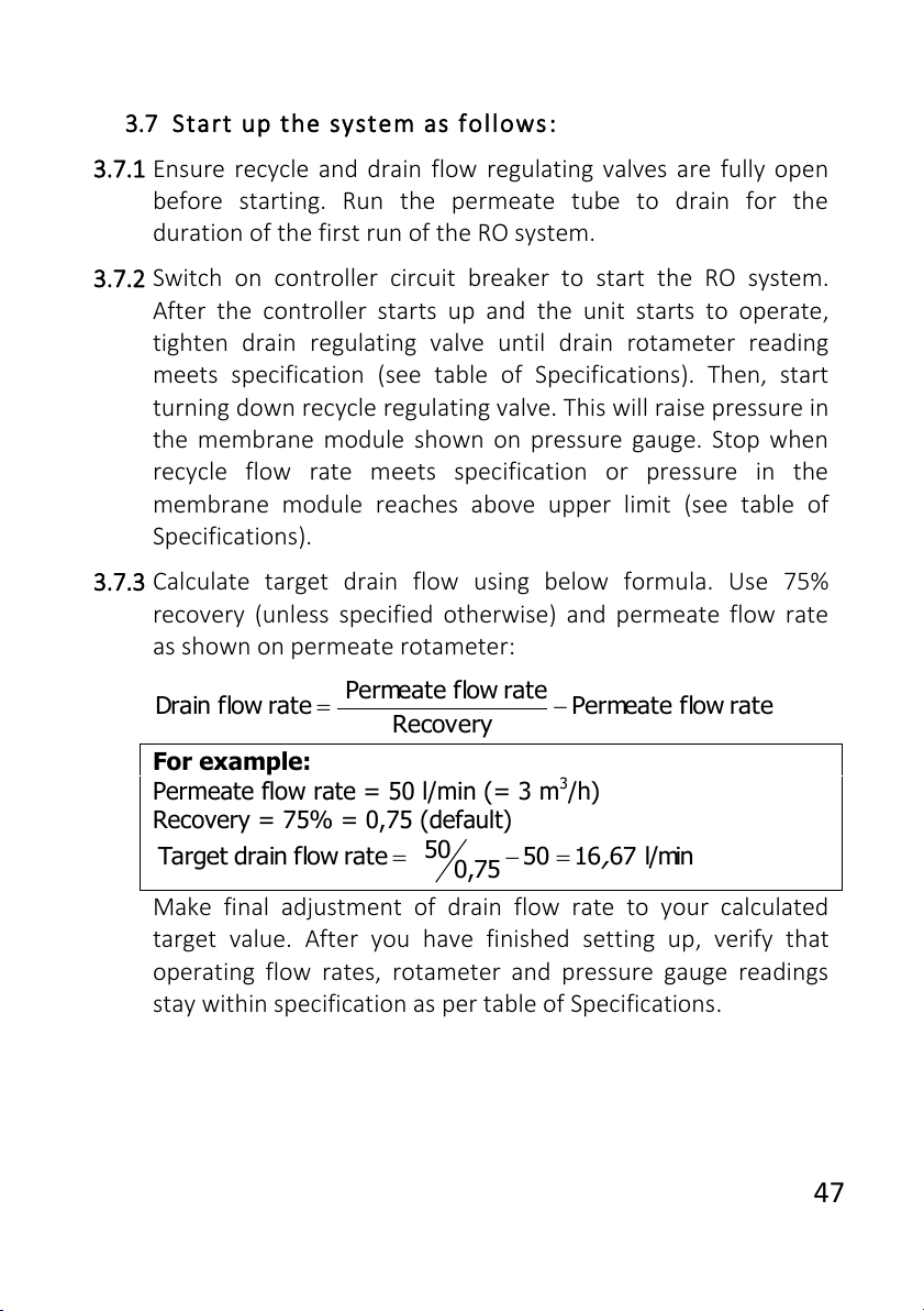
3.7.3 Calculate target drain flow using below formula. Use 75%
recovery (unless specified otherwise) and permeate flow rate
as shown on permeate rotameter:
rateflowPermeate
Recovery
rateflowPermeate
rateflowDrain
For example:
Permeate flow rate = 50 l/min (= 3 m3/h)
Recovery = 75% = 0,75 (default)
l/min671650
75,0
50
rateflowdrainTarget
,
Make final adjustment of drain flow rate to your calculated
target value. After you have finished setting up, verify that
operating flow rates, rotameter and pressure gauge readings
stay within specification as per table of Specifications.
48
Take care not to exceed 1,4 MPa in membrane module at
any time. If membrane pressure rises above the upper
limit in specification, open recycle flow regulating valve to
bring it down.
Drain flow rate must not go below the calculated target
value at any time. If at some point drain flow rate lowers,
loosen drain flow regulating valve to raise it back.
Turn regulating valve knobs smoothly when regulating
recycle and drain flow. Do not make rapid turns or apply
disproportionate force as this can damage the unit.
3.7.4 Let the unit run for 1 hour discarding permeate and
concentrate to drain to flush out membrane preservative.
Watch pressure and flow rate readings to make sure these do
not exceed requirements.
After 1 hour of operation, start forward flush cycle (by pressing
�START on controller front panel), then stop the unit. Switch
off main circuit breaker. Connect permeate tube/hose to
permeate tank. The RO system is ready for operation.
R
RO
OS
SY
YS
ST
TE
EM
M
4 Installation requirements
�Installation and setup of the unit should be undertaken by a
qualified professional. Room or area where the unit is to be installed
must meet workplace standards of local building code.
�The unit must not be operated in outdoor environments. Do not
expose to weather conditions (rain, temperature fluctuations,
proximity of heating equipment, direct sunlight etc).
�Air at workplace should be free of corrosive vapors, airborne
dust, and fibrous matter.
�To provide access to the unit for maintenance and repair
purposes, respect the following clearances between the unit and
building structures: 500 mm to the left or right, 200 mm above.
49
Electrical connections must comply with local electrical code.
Make sure to follow applicable grounding and insulation rules.
Supply, drain, and delivery pipework must comply with local
plumbing code and have sufficient flow capacity. Drain line of the
unit must be separated from floor drain with an air gap.
Construction material or inside lining of permeate tank must be
resistant to water corrosion (e. g. stainless steel, polypropylene).
Tank should be installed next to the unit.
Antiscalant pump suction line length should not exceed 1,5 m.
Refer to dosing pump’s manual to adjust pump’s settings if it has not
been factory configured.
R
RO
O
S
SY
YS
ST
TE
EM
M
5Operating requirements
5.1 Operator of the unit must strictly follow these guidelines and
general electrical safety precautions.
If power supply cord is damaged, it must be replaced by
the manufacturer, its service agent or similarly qualified
person in order to avoid hazard.
5.2 When operating the unit, ensure that pressure and flow rates
are within specification limits and that power supply is clean and
uninterrupted.
5.3 Perform the following at least once a month:
–verify that readings on pressure gauges and rotameters fall
within the specified range per requirements specification;
–verify tightness of hydraulic connections and integrity of parts.
5.4 In order to monitor performance of the RO machine, regularly
keep record of operation and write down parameter readings. Use
membrane manufacturer’s software tools for normalization to
control for fluctuations of pressure, temperature, and other
operating conditions.
50
5.5 Change polypropylene cartridge when it has clogged. Pressure
drop of 0,1 MPa or greater on the sediment filter indicates that filter
cartridge needs to be replaced as soon as possible.
5.6 Perform CIP or another suitable chemical cleaning protocol
when any of the following conditions are encountered:
–normalized permeate flow rate drops 10-15% of its initial value;
–normalized conductivity of permeate increases 10-15% of initial
value, raw water conductivity remaining at the same level;
–normalized pressure drop along the membrane module
increases 10-15% of its initial value.
5.7 After installing freshly cleaned membrane, perform 1 hour
rinse discarding all permeate and concentrate. If chemical cleaning
fails to restore normalized flow or rejection to design specifications,
membrane element is irreparably fouled and has to be replaced.
5.8 To prevent microbial contamination, the unit should be
operated for at least 1 hour a day. In case 48 hours or longer
shutdown is to occur, membrane should be treated with preservative
solution. Preservative treatment is accomplished by circulating 1%
sodium metabisulfite solution through the membrane module for
30 minutes or by preparing metabisulfite solution of the above
strength in the module. Before resuming operation of a machine that
had been treated with preservative, rinse the membrane.
Do not use raw water with over 0,1 mg/L of free chlorine
without pre-treatment with activated carbon or other means
of dechlorination. Chlorine will destroy the membrane.
5.9 To replace sediment filter cartridge proceed as follows:
–remove the power from the unit;
–shut off water supply and relieve pressure;
–screw off filter bowl and remove it, taking care not to spill
water on parts of the unit;

51
–remove spent cartridge from the bowl, place a clean one inside
and screw the bowl back on.
Do not torque over 2 kgf×m
when tightening bowl.
5.10 To replace membrane element proceed as follows:
–remove the power from the unit;
–shut off water supply and relieve pressure;
–disconnect feed, permeate, and concentrate tube connections
at membrane module outlets;
–remove caps from the pressure vessel;
–push the membrane element from the feed end towards the
discharge end (in the direction of the arrow). Extract the membrane
element by pulling it at the discharge end of the vessel;
–install new membrane element, observing flow direction as
indicated by the arrow;
–fasten the caps and re-connect tubes back to the vessel.
Do not perform any maintenance, repair, cleaning, moving
the unit or ancillary units (permeate tank, media filters etc),
when the unit is connected to power and water supply.
Do not subject pressure vessel to mechanical impact
(shocks, static load etc).
The manufacturer shall not be held liable for any damages
incurred by the owner of the unit or any third party due to
failure to adhere to the safety precautions or installation
guidelines herein.

52
R
RO
O
S
SY
YS
ST
TE
EM
M
6Shipping and storage requirements
The unit must be stored indoors. Ambient air quality must
meet workplace standards.
Carry out preservative treatment of membrane elements
when preparing for an extended downtime.
The RO machine in its original packaging can be shipped by all
types of air, sea or ground transport.
During transportation, the unit must be protected from
exposure to low temperatures and jolts/vibration.
53
R
RO
O
S
SY
YS
ST
TE
EM
M
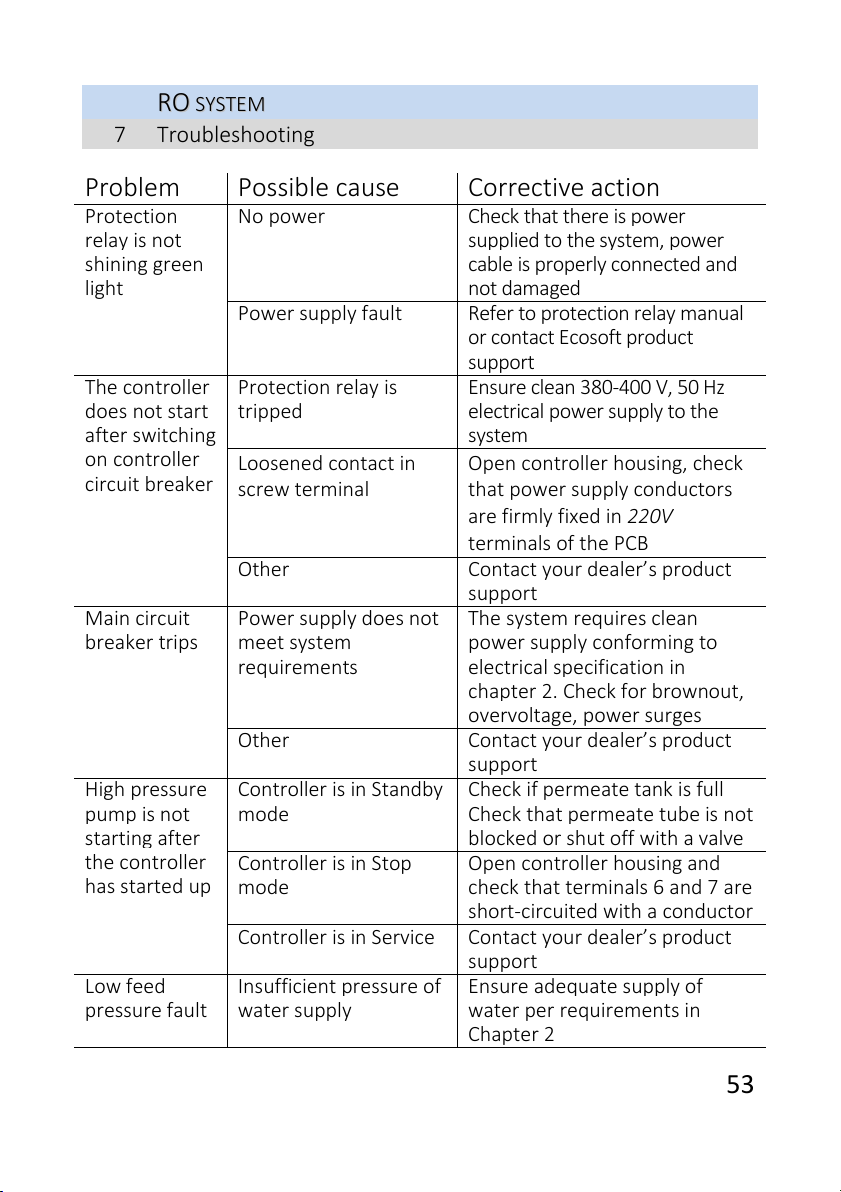
7Troubleshooting
Problem
Possible cause
Corrective action
Protection
relay is not
shining green
light
No power
Check that there is power
supplied to the system, power
cable is properly connected and
not damaged
Power supply fault
Refer to protection relay manual
or contact Ecosoft product
support
The controller
does not start
after switching
on controller
circuit breaker
Protection relay is
tripped
Ensure clean 380-400 V, 50 Hz
electrical power supply to the
system
Loosened contact in
screw terminal
Open controller housing, check
that power supply conductors
are firmly fixed in 220V
terminals of the PCB
Other
Contact your dealer’s product
support
Main circuit
breaker trips
Power supply does not
meet system
requirements
The system requires clean
power supply conforming to
electrical specification in
chapter 2. Check for brownout,
overvoltage, power surges
Other
Contact your dealer’s product
support
High pressure
pump is not
starting after
the controller
has started up
Controller is in Standby
mode
Check if permeate tank is full
Check that permeate tube is not
blocked or shut off with a valve
Controller is in Stop
mode
Open controller housing and
check that terminals 6 and 7 are
short-circuited with a conductor
Controller is in Service
Contact your dealer’s product
support
Low feed
pressure fault
Insufficient pressure of
water supply
Ensure adequate supply of
water per requirements in
Chapter 2
54
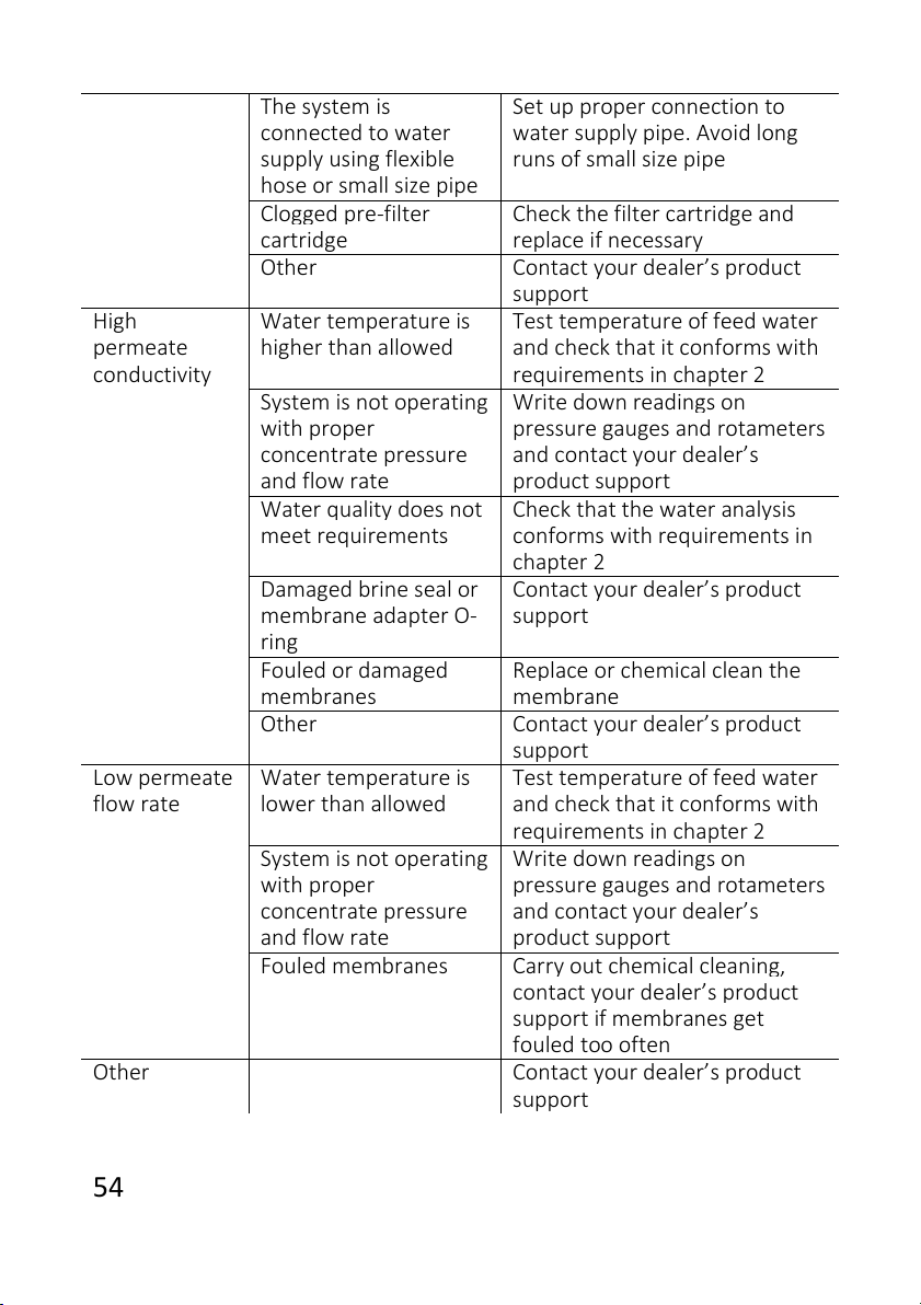
The system is
connected to water
supply using flexible
hose or small size pipe
Set up proper connection to
water supply pipe. Avoid long
runs of small size pipe
Clogged pre-filter
cartridge
Check the filter cartridge and
replace if necessary
Other
Contact your dealer’s product
support
High
permeate
conductivity
Water temperature is
higher than allowed
Test temperature of feed water
and check that it conforms with
requirements in chapter 2
System is not operating
with proper
concentrate pressure
and flow rate
Write down readings on
pressure gauges and rotameters
and contact your dealer’s
product support
Water quality does not
meet requirements
Check that the water analysis
conforms with requirements in
chapter 2
Damaged brine seal or
membrane adapter O-
ring
Contact your dealer’s product
support
Fouled or damaged
membranes
Replace or chemical clean the
membrane
Other
Contact your dealer’s product
support
Low permeate
flow rate
Water temperature is
lower than allowed
Test temperature of feed water
and check that it conforms with
requirements in chapter 2
System is not operating
with proper
concentrate pressure
and flow rate
Write down readings on
pressure gauges and rotameters
and contact your dealer’s
product support
Fouled membranes
Carry out chemical cleaning,
contact your dealer’s product
support if membranes get
fouled too often
Other
Contact your dealer’s product
support
55
C
CO
ON
NT
TR
RO
OL
LL
LE
ER
R
1Overview
Ecosoft OC5000 process controller provides means to control
operation of RO machine via succinct user interface comprising two
buttons and LED display. The controller is designed to ensure
complete automation of the process while allowing for manual
intervention on user part at any moment in time. When running a
reverse osmosis machine, the controller executes the following tasks:
turning the unit on and off with respect to tank permeate level
and/or backpressure switch status;
reading status of level, pressure, and stop switches; conductivity
and temperature of permeate;
going into Fault mode upon occurrence of any of the conditions
indicating risk of damage to the RO machine or improper
operation;
performing hydraulic flushing of membranes (‘forward flush’)
with preset frequency and duration;
implementing manual control over the unit.
In order to deliver the above functionality, Ecosoft process
controller supports the following connectivity:
–5 dry contact switches (NC/NO);
–3 electrical valves (solenoid or motor driven valves can be used);
–alarm signal;
–high pressure pump, antiscalant and/or biocide dosing pumps;
–temperature and electrical conductivity probes.
The controller supports scheduled maintenance alerts and
passcode protected access to configuration menu. Conductivity
reading is digitally corrected for temperature of permeate, while
hardware interface offers good interference immunity and reliability
with galvanically isolated terminal connections.
56
C
CO
ON
NT
TR
RO
OL
LL
LE
ER
R
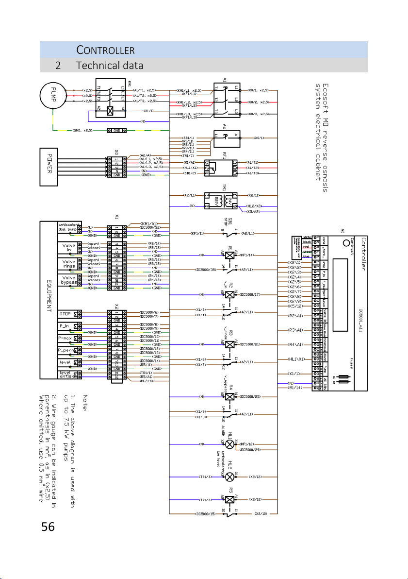
2Technical data
This manual suits for next models
5
Table of contents
Other Ecosoft Industrial Equipment manuals


Popular Industrial Equipment manuals by other brands

Interactive Instruments
Interactive Instruments Jet Stream 500 instruction manual

NTN
NTN MD10 Series instruction manual

IRO
IRO Stella 290 operating instructions

GREER Company
GREER Company MicroGuard RCI 510 Operation

Synventive
Synventive 16SVH installation guide

Idex
Idex PULSAFEEDER DGF1 operating instructions


