WattMaster OE230 User manual
FILENAME
DATE: B. CREWS
DESCRIPTION:
PAGE
DRAWN BY:
Duct Temperature Sensor
1
JOB NAME
07/13/15
G-DUCSENS1.CDR
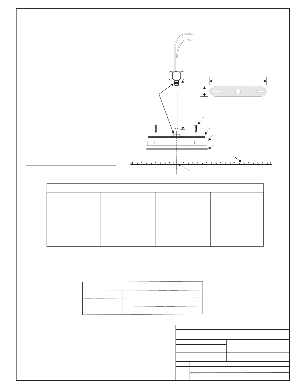
OE230 & OE231
Duct Temperature Sensors
OE230 (6" Probe) & OE231 (12" Probe)
Mounting Plate
Gasket
Adhesive Backed Drill Guide
Mounting Template
11-1/2" (OE231)
5-1/2" (OE230) Mounting Plate
4.0"
3/4"
1/4" Hex Head Sheet Metal Screws
Thread
Together
Duct Work
Drill 3/8” Hole In Ductwork For Probe
Leads Are Non-polarized.
Butt Splice Leads To 24 Gauge
Wire Minimum. Connect Leads
To "Analog In" And "Ground"
At Controller.
Notes:
1.)All Wiring To Be In Accordance With
Local And National Electrical Codes
And Specifications.
Temperature Sensor Resistance/Voltage Chart
Temp Resistance* Voltage
F Ohms @ Input*
-10.............93333........4.620
-5...............80531........4.550
0 ...............69822 ........4.474
5 ...............60552 ........4.390
10..............52500........4.297
15..............45902........4.200
20..............40147........4.095
25..............35165........3.982
30..............30805........3.862
35..............27140........3.737
40..............23874........3.605
°
Temp Resistance* Voltage
F Ohms @ Input*°
45..............21094........3.470
50..............18655........3.330
52..............17799........3.275
54..............16956........3.217
56..............16164........3.160
58..............15385........3.100
60..............14681........3.042
62..............14014........2.985
64..............13382........2.927
66..............12758........2.867
68..............12191........2.810
Temp Resistance* Voltage
F Ohms @ Input*°
69..............11906 ........2.780
70..............11652 ........2.752
71..............11379 ........2.722
72..............11136 ........2.695
73..............10878........2.665
74..............10625........2.635
75..............10398........2.607
76..............10158........2.570
78..............9711 ..........2.520
80..............9302..........2.465
82..............8893..........2.407
Temp Resistance* Voltage
F Ohms @ Input*
84..............8514..........2.352
86..............8153..........2.297
88..............7805..........2.242
90..............7472..........2.187
95..............6716..........2.055
100............6047..........1.927
105............5453..........1.805
110 ............4923 ..........1.687
115 ............4449 ..........1.575
120............4030..........1.469
°
125............3656..........1.369
*Chart Notes:
1. Use the resistance column to check the thermistor sensor while disconnected from the controllers (not powered).
2. Use the voltage column to check sensors while connected to powered controllers. Read voltage with meter set on DC volts.
Place the "-"(minus) lead on GND terminal and the "+"(plus) lead on the sensor input terminal being investigated. If the voltage
is above 5.08 VDC, the sensor or wiring is "open." If the voltage is less than 0.05 VDC, the sensor or wiring is shorted.
The Duct Sensor Is Used For Sensing Supply
Or Return Air Temperatures. Location Of The
Sensors Is Very Important In Order To Obtain
Accurate Temperature Readings. The
Following Recommendations Should Be
Followed:
When Used As A Supply Air Sensor The
Sensor Should Be Mounted In The Supply Air
Duct As Close To The HVAC Unit As Possible
And Upstream Of The Bypass Damper (If
Used) For Best Results. For Best Accuracy,
Apply Insulation On The Outside Of The
Ductwork Over The Sensor. This Will Help
Thermal Gradients From Affecting The Sensor.
Supply Air
Return Air
When Used As A Return Air Sensor The
Sensor Should Be Mounted In The Return Air
Duct As Close To The HVAC Unit As Possible
And Upstream Of The Bypass Damper (If
Used) For Best Results. For Best Accuracy,
Apply Insulation On The Outside Of The
Ductwork Over The Sensor. This Will Help
Thermal Gradients From Affecting The Sensor.
See The Systems Installation And Operation
Manual For Other Design Considerations And
Recommendations Regarding Duct
Temperature Sensor Location.
Caution!
Technical Specifications
Sensor Element:
Type III Thermistor 10k ohm @ 77ºF
Accuracy:
±0.4º F between 40º F to 95º F
Range:
-30º F to 150º F
FILENAME
DATE: B. CREWS
DESCRIPTION:
PAGE
DRAWN BY:
Water Temperature Sensor Thermowell
1
JOB NAME
07/09/04
G-OE291-T-Well.CDR
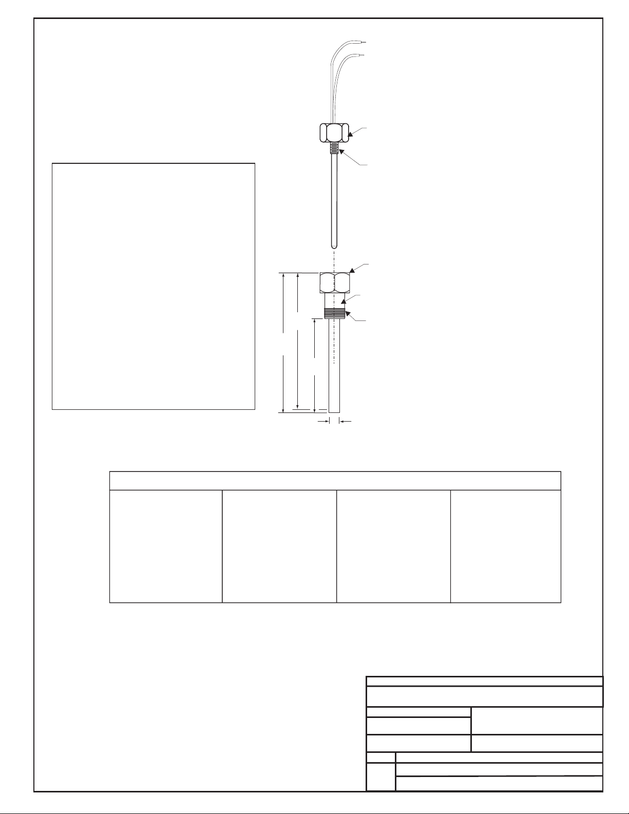
OE291
OE291 Thermowell Assembly
Using OE230 Temperature Sensor
Notes:
1.)All Wiring To Be In Accordance With
Local And National Electrical Codes
And Specifications.
Temperature Sensor Resistance/Voltage Chart
Temp Resistance* Voltage
F Ohms @ Input*
-10.............93333........4.620
-5...............80531........4.550
0 ...............69822 ........4.474
5 ...............60552 ........4.390
10..............52500........4.297
15..............45902........4.200
20..............40147........4.095
25..............35165........3.982
30..............30805........3.862
35..............27140........3.737
40..............23874........3.605
°
Temp Resistance* Voltage
F Ohms @ Input*°
45..............21094........3.470
50..............18655........3.330
52..............17799........3.275
54..............16956........3.217
56..............16164........3.160
58..............15385........3.100
60..............14681........3.042
62..............14014........2.985
64..............13382........2.927
66..............12758........2.867
68..............12191........2.810
Temp Resistance* Voltage
F Ohms @ Input*°
69..............11906 ........2.780
70..............11652 ........2.752
71..............11379 ........2.722
72..............11136 ........2.695
73..............10878........2.665
74..............10625........2.635
75..............10398........2.607
76..............10158........2.570
78..............9711 ..........2.520
80..............9302..........2.465
82..............8893..........2.407
Temp Resistance* Voltage
F Ohms @ Input*
84..............8514..........2.352
86..............8153..........2.297
88..............7805..........2.242
90..............7472..........2.187
95..............6716..........2.055
100............6047..........1.927
105............5453..........1.805
110 ............4923 ..........1.687
115 ............4449 ..........1.575
120............4030..........1.469
°
125............3656..........1.369
*Chart Notes:
1. Use the resistance column to check the thermistor sensor while disconnected from the controllers (not powered).
2. Use the voltage column to check sensors while connected to powered controllers. Read voltage with meter set on DC volts.
Place the "-"(minus) lead on GND terminal and the "+"(plus) lead on the sensor input terminal being investigated. If the voltage
is above 5.08 VDC, the sensor or wiring is "open." If the voltage is less than 0.05 VDC, the sensor or wiring is shorted.
The Duct Sensor Is Used For Sensing Entering Or
Leaving Water Temperatures. Location Of The
Sensors Is Very Important In Order To Obtain
Accurate Temperature Readings. The Following
Recommendations Should Be Followed:
When Used As A Supply Water Temperature
Sensor The Sensor Should Be Mounted In The
Supply Water Piping As Close To The Water Coil
As Possible For Best Accuracy, Apply Insulation
On The Outside Of The Piping Over The Sensor.
This Will Help Thermal Gradients From Affecting
The Sensor.
Entering Water
Leaving Water
When Used As A Leaving Water Temperature
Sensor The Sensor Should Be Mounted In The
Return Piping As Close To The Water Coil Outlet
As Possible. For Best Accuracy, Apply Insulation
On The Outside Of The Piping Over The Sensor.
This Will Help Thermal Gradients From Affecting
The Sensor.
See The Systems Installation And Operation
Manual For Other Design Considerations And
Recommendations Regarding Water Temperature
Caution!
1/8 -27 NPSM Internal Thread"
1/8 -27 NPT External Thread"
1/2" NPT External Thread
3.25"
0.5"
5.13"
4.94
OE291 Stainless Steel Thermowell
Leads Are Non-polarized.
Butt Splice Leads To 24
Gauge Wire Minimum.
Connect Leads To
"Analog In" And "Ground"
At Controller.
The OE230 Duct Sensor Threads Into
The OE291 Stainless Steel Thermowell.
The OE291 Thermowell Threads Into A
1/2” FPT Elbow or Tee in the Water Piping
of the Water Coil at Which You wish to
Measure the Water Temperature. The
Pipe must be a minimum of 4” Diameter
or an Extended Tee and Bushing
Configuration Must be Used to
Accommodate the Length of the
Thermowell Assembly.
"
OE230 Temperature Sensor
(Ordered Separately)
CONTROLS
FILENAME
DATE: 07/09/04 B. CREWS
DESCRIPTION:
PAGE
DRAWN BY:
G-OE233-W-TempSnsr1a.CDR
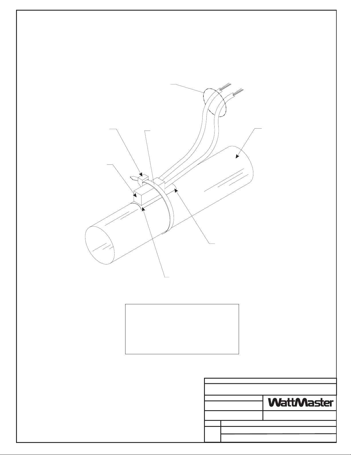
OE233 - Strap-On Temperature
Sensor Kit Installation
1
JOB NAME
Place Between Pipe
And Sensing Element. Pipe Should Be
Clean And Smooth To Provide Proper
Thermal Contact With Sensing Element.
Thermal Mastic
Secure Sensor Element And Thermal
Mastic Strip To Pipe With Supplied
Wire Tie. Be Sure To Tighten Wire Tie
Snugly To Ensure Good Thermal Contact
Between Pipe And Sensing Element.
Butt Splice Or Wire Nut Wire Leads And Extend
Wire To Controller Terminals. Connect One Wire
Lead To Return Water Temperature Or Supply Water
Temperature Terminal At The Controller As Required
By Intended Use. Secure Other Wire Lead To
Ground Terminal At The Controller. See Note 3.
Notes:
1.)Sensor Should Be Mounted At
Location Along Pipe Length
That Best Represents Desired
Temperature Reading.
3.)All Wiring To Be In Accordance
With Local And National Electrical
Codes And Specifications.
2.)Sensing Element Shown
Mounted To Top Of Pipe. The
Sensor Element May Be Located
At Any Location Around Pipe.
Wire Tire
(Supplied)
Sensing Element
(Supplied)
Thermal Mastic Strip
(Supplied)
Supply Or Return
Water Pipe. See Note1&2.
Important Note:
For Accurate Temperature Readings
It Is Necessary To Place Insulation Over
The Sensor After Installation. This Prevents
The Ambient Temperature From Affecting
The Sensor. Insulation Should Cover The
Sensor And Extend 6“ to 12” Beyond Each
End Of The Sensor.
4.)All Wiring To Be In Accordance With
Local And National Electrical Codes
And Specifications.
3.)Gasket Must Be Installed Under Cover
Plate To Provide Raintight Seal.
Rainwater Can Damage Sensor!
Temperature Sensor Resistance/Voltage Chart
Temp Resistance* Voltage
F Ohms @ Input*
-10.............93333........4.620
-5...............80531........4.550
0 ...............69822 ........4.474
5 ...............60552 ........4.390
10..............52500........4.297
15..............45902........4.200
20..............40147........4.095
25..............35165........3.982
30..............30805........3.862
35..............27140........3.737
40..............23874........3.605
°
Temp Resistance* Voltage
F Ohms @ Input*°
45..............21094........3.470
50..............18655........3.330
52..............17799........3.275
54..............16956........3.217
56..............16164........3.160
58..............15385........3.100
60..............14681........3.042
62..............14014........2.985
64..............13382........2.927
66..............12758........2.867
68..............12191........2.810
Temp Resistance* Voltage
F Ohms @ Input*°
69..............11906 ........2.780
70..............11652 ........2.752
71..............11379 ........2.722
72..............11136 ........2.695
73..............10878........2.665
74..............10625........2.635
75..............10398........2.607
76..............10158........2.570
78..............9711 ..........2.520
80..............9302..........2.465
82..............8893..........2.407
Temp Resistance* Voltage
F Ohms @ Input*
84..............8514..........2.352
86..............8153..........2.297
88..............7805..........2.242
90..............7472..........2.187
95..............6716..........2.055
100............6047..........1.927
105............5453..........1.805
110 ............4923 ..........1.687
115 ............4449 ..........1.575
120............4030..........1.469
°
2.)Unused Conduit Opening(s) Must
Have Closure Plugs Installed And Must
Be Coated with Sealing Compound To
Provide Raintight Seal. Water Can
Damage Sensor!
1.)The Outside Air Sensor Must Be
Mounted In A Vertical Position As
Shown (Sensor Tube Pointing
Down).
Sensor Must Be Located
Where It Will Not Be Affected By
Direct Sunlight Or Heat Producing
Equipment. If Possible Mount Under
Roof Eave Or Similar Protected
Location. If Sensor Is Not Located
As Specified, Erroneous Outside Air
Temperature Readings Will Result.
Water Must Not Be
Allowed To Stand In Sensor
Tube. Rainwater Will Damage
Sensor.
*Chart Notes:
1. Use the resistance column to check the thermistor sensor while disconnected from the controllers (not powered).
2. Use the voltage column to check sensors while connected to powered controllers. Read voltage with meter set on DC
volts. Place the "-"(minus) lead on GND terminal and the "+"(plus) lead on the sensor input terminal being investigated. If
the voltage is above 5.08 VDC, then the sensor or wiring is "open." If the voltage is less than 0.05 VDC, the sensor or
wiring is shorted.
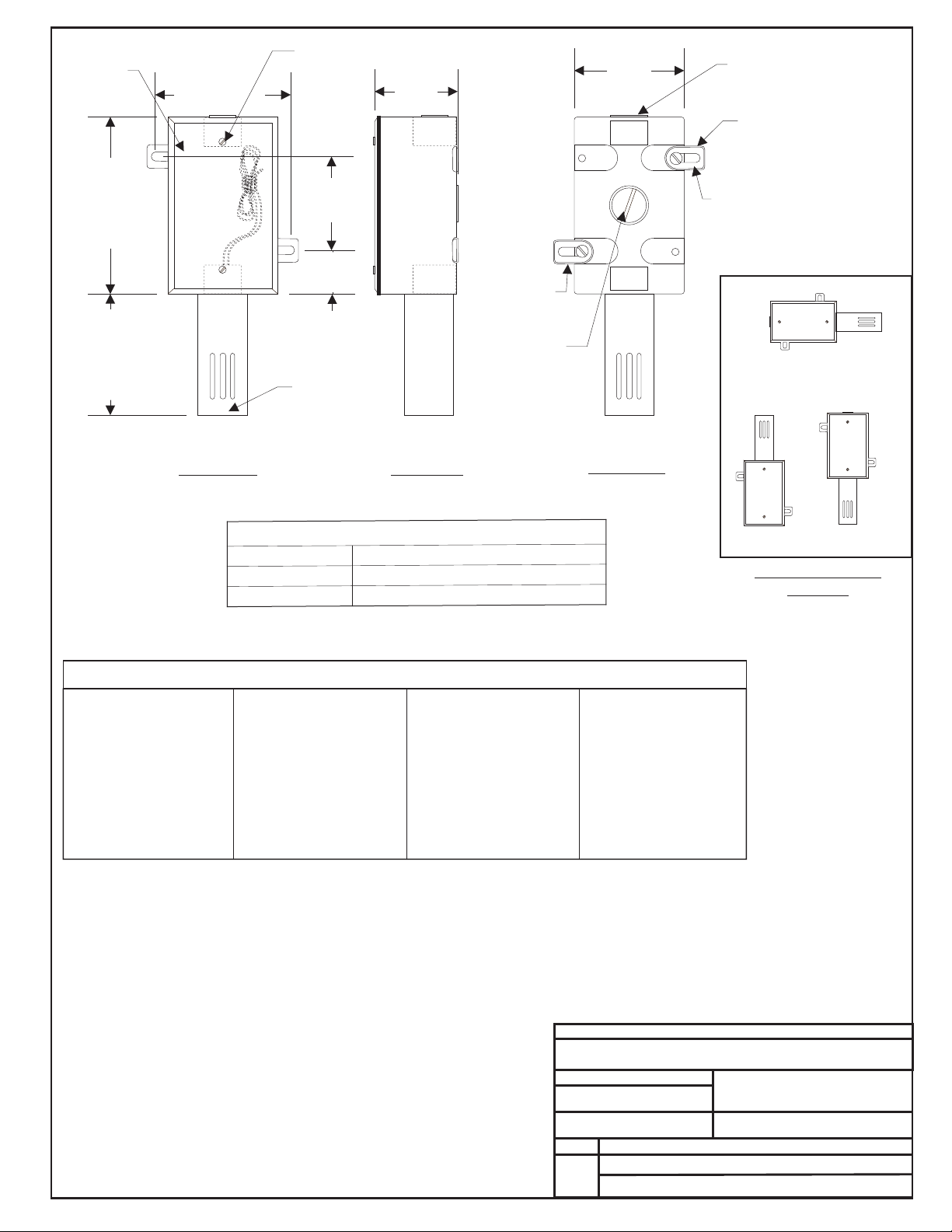
Outside Air Sensor OE250
Notes:
Closure Plug
CAUTION!
See Note 2
Gasketed Cover
CAUTION!
See Note3
Cover
Mounting
Screw - Typ.
Mounting Tab
& Screw - Typ.
0.21" Dia. x 0.73
Lg. Slot - Typ.
4.50”
2.25”
3.00”
FILENAME
DATE: B. CREWS
DESCRIPTION:
PAGE
DRAWN BY:
Outside Air Temperature Sensor
1
JOB NAME
07/13/15
G-OE250-OAS-PDWG.CDR
OE250
Front View Side View Back View
Closure Plug
CAUTION!
See Note 2
Sensor Tube
CAUTION!
See Note 1
Mounting Tab
& Screws - Typ.
Correct
Incorrect
Incorrect
See Note #1
Sensor Mounting
Postion
2.70”
1.13”
2.30”
3.00”
Technical Specifications
Sensor Element:
Type III Thermistor 10k ohm @ 77ºF
Accuracy:
±0.4º F between 40º F to 95º F
Range:
-30º F to 150º F
JOB NAME
FILE NAME
G-OE265-11-SPHUMID1E.PDF
DATE: 08/10/15
PAGE DESCRIPTION
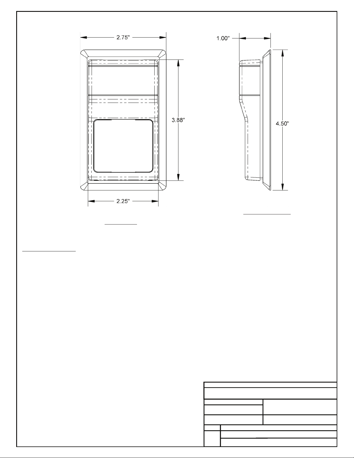
OE265-11
Space Humidity Sensor – 0-5 VDC
DRAWN BY: B. CREWS
Notes:
1.) The sensor is designed to be wall
mounted in rooms where appearance is
important. It may be mounted directly on
dry wall or on any single gang electrical
outlet box with no adapters required.
Toggle bolts or other direct wall mount
screws can be used where conduit is not
required. It includes a detachable
mounting plate. The cover is secured with
tamper-resistant hex screws. The sensor
should be mounted approximately five feet
above the floor, on an interior wall, away
from any heating or cooling generating
devices, and out of the sun. Plug the
wireway hole to prevent false readings by
air drafts within the wall.
2.) All Wiring To Be In
Accordance With Local
And National Electrical
Codes And Specifications.
1 of 2
Installation Instructions:
1.) Place The SpaceHumidity Sensor Where It Is To Be Mounted. See Note 1 Below For Important Mounting Information And Considerations.
2.) Remove The Humidity Sensor Cover By Screwing In The 2 Allen Screws That Secure It To The Base.
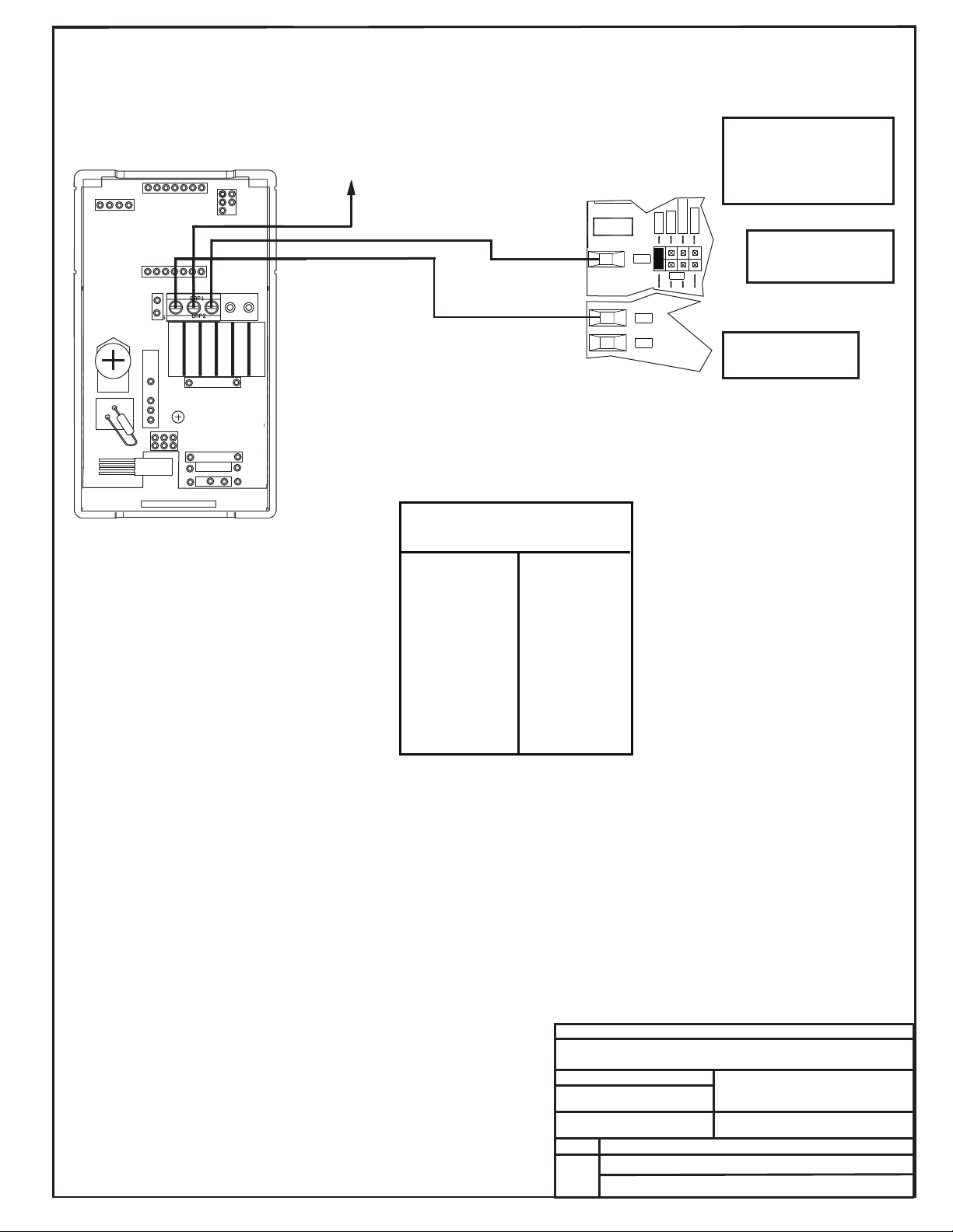
3.) Connect All Of The Wires From The Controller Board To The Corresponding Terminal Blocks Per The Wiring Diagram On Page 2 Of This Drawing.
4.) Secure The Cover Onto The Base Housing By Snapping The Cover Onto The Base And Backing Out The 2 Allen Screws.
5.) Verify That You Are Getting A Humidity Reading On Your Control System. Please Note That It May Take Ten To Twenty Minutes For The Sensor
Reading To Stabilize Upon Initial Power Up.
Front View
Right Side View
Notes:
1.) All Wiring To Be In Accordance With Local And
National Electrical Codes And Specifications.
FILENAME
DATE: B. CREWS
DESCRIPTION:
PAGE
DRAWN BY:
JOB NAME
2 of 2 Wall Mounted Humidity Sensor - 0-5 VDC
OE265-11
08/10/15
G-OE265-11-SPHUMID1E.CDR
NOTE: RESISTOR IS NOT
REQUIRED FOR CONTROLLERS
THAT HAVE JUMPER
SELECTABLE ANALOG INPUTS.
NOTE: RESISTOR IS REQUIRED
FOR CONTROLLERS THAT DO
NOT HAVE JUMPER
SELECTABLE ANALOG INPUTS.
THE PULL-UP RESISTOR (PUx)
FOR THE ASSOCIATED ANALOG
INPUT MUST BE REMOVED FROM
THE CONTROLLER BOARD FOR
THE SENSOR TO OPERATE
24 VAC or VDC
JUMPER SELECTABLE
STYLE CONTROLLER
TERMINAL. SET FOR 0-5V.
CONNECT TO SPECIFIED AIx
TERMINAL FOR YOUR
APPLICATION. SEE SPECIFIC
WIRING DIAGRAM FOR YOUR
APPLICATION FOR CORRECT
AIX TERMINAL TO BE USED.
CONNECT TO GROUND
TERMINAL FOR YOUR
ANALOG INPUT(S).
INPUTS
ANALOG
0-5v
0-10v
4-20 mA
TB3
AI1
AI1
THERM
0-5VDC Terminal
Label: LB101969
Gnd
Vin
Vo
Not Used
Not Used
RH Output
% VDC
55 ........ 2.75
60 ........ 3.00
65 ........ 3.25
70 ........ 3.50
75 ........ 3.75
80 ........ 4.00
85 ........ 4.25
90 ........ 4.50
95 ........ 4.75
100 ........ 5.00
RH Output
% VDC
5 .......... 0.25
10 .......... 0.50
15 .......... 0.75
20 .......... 1.00
25 .......... 1.25
30 .......... 1.50
35 .......... 1.75
40 .......... 2.00
45 .......... 2.25
50 .......... 2.50
Humidity Sensor
RH/Voltage Chart
GND
GND
Chart Notes
1.) First be sure that the +24 VAC power is being supplied to the
sensor. Second set the meter to DC volts and connect the meter
between ground and the 0-5 VDC input on the controller board or
between the 0-5 VDC output terminal on the sensor and its ground
terminal. Use an accurate humidity measurement device (such as an
aspirating psychrometer) to determine the RH percentage (relative
humidity) .
Use the “Output VDC” column on the chart to read the voltage
corresponding with the RH percentage column just measured. If the
measured voltage is within 3% of what is listed for the corresponding
RH, the sensor is functioning correctly. If it is not you will need to
replace the sensor.
JOB NAME
FILE NAME
G-OE265-13B-OAHUMID-1E.PDF
DATE: 08/17/11
PAGE DESCRIPTION
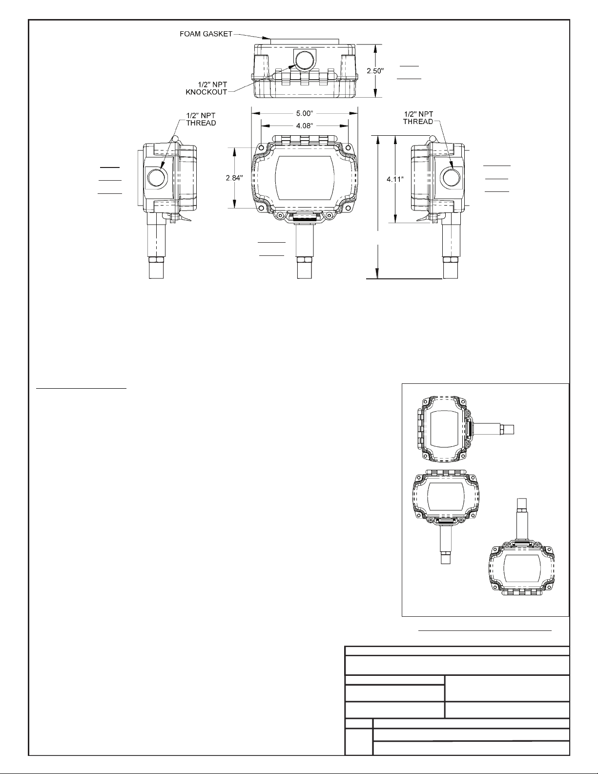
Outside Air Humidity Sensor –0-5 VDC
DRAWN BY: B. CREWS
Notes:
1.) The Outside Air Humidity Sensor Must
Be Mounted In A Vertical Position As Shown
(Sensor Tube Pointing Down). Water Must
Not Be Allowed To Stand In Sensor Tube,
it Will Cause Erroneous Sensor
Readings. The Sensor will recover when
it dries out.Sensor Must Be Located
Where It Will Not Be Affected By Direct
Sunlight Or Heat Producing Equipment. If
Possible Mount Under Roof Eave Or Similar
Protected Location.If Sensor Is Not
Located As Specified, Erroneous Outside Air
Humidity Readings Will Result.
2.) Unused Conduit Opening(s) Must
Not be Knocked Out to Prevent Dust
or Insects From Infiltrating the Sensor
Electrical Box.
3.) All Wiring To Be In Accordance
With Local And National Electrical
Codes And Specifications.
1 of 2
Installation Instructions:
1.) Place The Outside Air Humidity Sensor Where It Is To Be Mounted. See Note 1 Below For
Important Mounting Information And Considerations. Mark The (4) Mounting Holes. Secure The
Humidity Sensor By Using The Four #10 X 1.5" Self Tapping Screws Included With The Humidity
Sensor.
2.) Open The Cover by Moving the Latch to the Side And Install Your Conduit Connectors. The
Cover Must Always Be Opened Before Attempting To Punch Out The Knockouts.
3.) Connect The Wires To The Corresponding Sensor Wire Leads Per The Wiring Diagram On
Page 2 Of This Drawing. Insert the Wires Into the Sealant Filled Connectors Provided and Crimp.
Lightly Tug on the Wire to Assure a Good Mechanical Connection
4.) Close The Cover by Pushing Down Until the Latch Snaps Into Place. Be Careful Not To Pinch
The Sensor Wires When Closing The Housing Cover.
5.) Verify That You Are Getting A Humidity Reading On Your Control System. Please Note That It
May Take Ten To Twenty Minutes For The Sensor Reading To Stabilize Upon Initial Power Up.
OE265-13 BAPI
Right
Side
Left
Side
Top
View
Front
View
View
View
7.21
Sensor Mounting Position
INCORRECT
CORRECT
INCORRECT
JOB NAME
FILE NAME
G-OE265-13B-OAHUMID-1E.PDF
DATE: 08/17/11
PAGE DESCRIPTION
OE265-13 BAPI
Outside Air Humidity Sensor –0-5 VDC
DRAWN BY: B. CREWS
2 of 2
Notes:
1.) All Wiring To Be In Accordance With Local And
National Electrical Codes And Specifications.
RH Output
%VDC
55 ........2.75
60 ........3.00
65 ........3.25
70 ........3.50
75 ........3.75
80 ........4.00
85 ........4.25
90 ........4.50
95 ........4.75
100........5.00
RH Output
% VDC
5..........0.25
10 ..........0.50
15 ..........0.75
20 ..........1.00
25 ..........1.25
30 ..........1.50
35 ..........1.75
40 ..........2.00
45 ..........2.25
50 ..........2.50
Humidity Sensor
RH/Voltage Chart
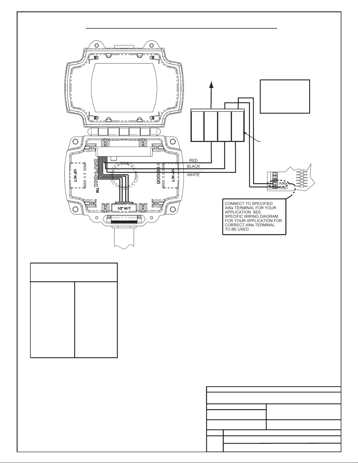
Warning
Be Sure To Observe
Polarity Or Serious
Damage To The
Board Could Result
0-5 VDC Output Wiring (24VAC Power)
*Chart Notes:
1. First, be sure that +24VAC power is being supplied to the sensor. Second check the
sensor output. Set the meter to DC volts and connect the meter between ground
and the 0-5 VDC input terminal on the controller board or between the 0-5 VDC
output on the sensor and its ground wire or you can measure voltage at the 0-5 VDC
and GND terminals on the sensor located at the sensor installtion location.
After measuring the voltage use an accurate humidity measurement device to
determine RH (relative humidity) such as an aspirating psychrometer. Use the
Output VDC column to read the Output Voltage corresponding with the RH
percentage measured with the psychrometer. If the measured voltage is within 3%
of what is listed for the corresponding RH, then the sensor is functioning properly.
CONNECT TO
24 VAC POWER
0-5VDC Terminal
Label: LB101966
RED
BLK
WHT
Not Used
VACorDC
GND
0-5V
SENSOR TERMINAL
BLOCK
JOB NAME
FILE NAME
G-OE265-14B-RAHUMID-1D.PDF
DATE: 08/28/07
PAGE DESCRIPTION
OE265-14 BAPI
Return Air Humidity Sensor –0-5 VDC
DRAWN BY: B. CREWS
Notes:
1.) The Sensor Should Be Mounted so
that the 6" Probe is in the Center of the
Return Air Duct. It Should be Mounted
Away from Fans, Elbows, Heating or
Cooling Coils or Other Equipment that
Could Affect the Measurement of
Relative Humidity. Also, the Sensor
Should be Mounted in an Area that
Receives Adequate Air Flow for Proper
Operation. The Sensor may be Mounted
Horizontally or Vertically to the Return Air
Duct. See the Sensor Mounting Diagram
Above.
2.) Unused Conduit Opening(s) Must Not
be Knocked Out to Prevent Dust or Insects
From Infiltrating the Sensor Electrical Box.
3.) The Sensor Probe Gasket Must Be
Installed Between the Back of the Sensor
Box and the Duct to Provide an Airtight
Seal.
4.) All Wiring To Be In Accordance With
Local And National Electrical Codes And
Specifications.
1 of 2
Installation Instructions:
1.) Drill a 1" Diameter Hole In The Duct Wall In the Location Where The Humidity Sensor Is To Be Mounted. Insert The Probe Of The Return Air Humidity
Sensor Through The Hole. See Note 1 Below For Important Mounting Information And Considerations. Mark The (4) Mounting Holes. Secure The
Humidity Sensor By Using The Four #10 X 1.5" Self Tapping Screws Included With The Humidity Sensor.
2.) Open The Cover by Moving the Latch to the Side And Install Your Conduit Connectors. The Cover Must Always Be Opened Before Attempting To
Punch Out The Knockouts.
3.) Connect The Wires To The Corresponding Sensor Wire Leads Per The Wiring Diagram On Page 2 Of This Drawing. Insert the Wires Into the Sealant
Filled Connectors Provided and Crimp. Lightly Tug on the Wire to Assure a Good Mechanical Connection
4.) Close The Cover by Pushing Down Until the Latch Snaps Into Place.Be Careful Not To Pinch The Sensor Wires When Closing The Housing Cover.
5.) Verify That You Are Getting A Humidity Reading On Your Control System. Please Note That It May Take Ten To Twenty Minutes For The Sensor
Reading To Stabilize Upon Initial Power Up.
Front View
Right
Side
View
Left
Side
View
Top
View
Mounting
Sensor to Duct
See Note #1

JOB NAME
FILE NAME
PAGE DESCRIPTION
Return Air Humidity Sensor –0-5 VDC
DRAWN BY: B. CREWS
2 of 2
RH Output
%VDC
55 ........2.75
60 ........3.00
65 ........3.25
70 ........3.50
75 ........3.75
80 ........4.00
85 ........4.25
90 ........4.50
95 ........4.75
100........5.00
RH Output
% VDC
5..........0.25
10 ..........0.50
15 ..........0.75
20 ..........1.00
25 ..........1.25
30 ..........1.50
35 ..........1.75
40 ..........2.00
45 ..........2.25
50 ..........2.50
Humidity Sensor
RH/Voltage Chart
Warning
Be Sure To Observe
Polarity Or Serious
Damage To The
Unit Could Result
0-5 VDC Output Wiring (24 VAC Power)
G-OE265-14B-RAHUMID-1D.PDF
DATE: 08/28/07
OE265-14 BAPI
Notes:
1.) All Wiring To Be In Accordance With Local And
National Electrical Codes And Specifications.
*Chart Notes:
1. First, be sure that +24VAC power is being supplied to the sensor. Second check the
sensor output. Set the meter to DC volts and connect the meter between ground
and the 0-5 VDC input terminal on the controller board or between the 0-5 VDC
output on the sensor and its ground wire or you can measure voltage at the 0-5 VDC
and GND terminals on the sensor located at the sensor installtion location.
After measuring the voltage use an accurate humidity measurement device to
determine RH (relative humidity) such as an aspirating psychrometer. Use the
Output VDC column to read the Output Voltage corresponding with the RH
percentage measured with the psychrometer. If the measured voltage is within 3%
of what is listed for the corresponding RH, then the sensor is functioning properly.
CONNECT TO
24 VAC POWER
0-5VDC Terminal
Label: LB101966
RED
BLK
WHT
Not Used
VACorDC
GND
0-5V
SENSOR TERMINAL
BLOCK

General Notes
FILENAME
DATE: B. CREWS
DESCRIPTION:
PAGE
DRAWN BY:
Pressure Sensor
1
JOB NAME
2.)All Wiring To Be In Accordance With Local And
National Electrical Codes And Specifications.
08/19/08
G-OE271TRAN1.CDR
OE271
Top View
Side View
OUT
IN
GND
UP
(-)LO
0.35"
0.55"
1.00"
2.20"
0.15" DIA.
0.15"
2.94"
2.50"
0.125" (1/8" Tubing Conn.)
0.200" (3/16" Tubing Conn.)
1.95"
0.60"
12.0" APPROX.
Full Scale Output
(Positive Pressure)
Null Offset
Span*
Minimum Typical Maximum
Hystereisis And Repeatability
Temperature Error
Null +10 To 40 C°°
Stability (1 Year)
Supply Voltage (Vs)
Pressure Overload
Burst Pressure
Positive Pressure (Hi Side)
Negative Pressure (Lo Side)
Positive Pressure (Hi Side)
Negative Pressure (Lo Side)
Non-Linearity
Span +10 To 40 C°°
Common Mode Pressure
0-5“ H O Pressure Range - 5 VDC Operation
2
3.92 VDC
0.17 VDC 0.2-0.3 VDC 0.33 VDC
3.59 VDC 3.91 VDC
±0.05 % Span
4.75 VDC 5.0 VDC 8.0 VDC
15 PSI
25“ H O
2
50“ H O
2
15“ H O
2
25“ H O
2
4.08 VDC
3.95-4.05 VDC
3.65-3.85 VDC
±0.3 % Span ±0.5 % Span
±0.03 % Span
±1.0 % Span
±0.5 % Span
±1.0 % Span
±1.5 % Span
±1.5 % Span
*Span Is The Algebraic Difference Between End Points (Null Offset And Full Scale Output)
The plastic housing on the sensor is electrically
conductive. Avoid contact with any electrical components.
It is acceptable to mount the sensor on grounded sheet
metal such as ductwork, electrical panels, etc.
Use extreme care when mounting the sensor to avoid
damage to the plastic housing. Do not overtighten the
mounting screws! Do not use mounting screws which are
too large for the holes!
Warning!
Warning!
1.) The Airflow Sensor Should Be Mounted In
A Vertical Position As Shown With Arrow Pointing
Up. ( Tubing Connections Pointing Down). If This
Mounting Position Is Not Possible In Your
Application, It May Be Mounted In A Horizontal
Position. When Mounted In A Horizontal Position
Accuracy Will Be Affected By Approximately 2% Full
Scale Null Shift Due To Diaphragm Gravity Effect
Error.
Caution:
1.29"
OUT (Black)
GND (Green)
IN (Red)
OE271
S.P. Sensor
OE271 - For
Applications Requiring 0-5“ H O Pressure Range
2
Airflow Sensor
When The OE271 Is Used As A Duct
It May Be Mounted To The
Ductwork Near The Static Pressure Pickup Tube. If
The Sensor Is Mounted In This Manner, Away
From The Controller, The Modular Plug Must Be
Cut Off And 3-conductor 24 Gauge Minimum Wire
Must Be Butt Spliced Between The Sensor And
The Modular Plug To Extend The Sensor Wire
Length. Total Wire Length Should Not Exceed
100Ft. If Desired The Sensor May Also Be Located
Near The Controller, With The Modular Plug On
The Sensor Directly Connected To The Mating
Controller Jack. When This Method Is Used Tubing
Must Be Run From The Sensor To The Static
Pressure Pickup Tube. Tubing Should Not Exceed
250 Ft. And Must Be Continuous Without Any
Splices.
Static
Pressure Sensor
When The OE271 Is Used As An Airflow
For VAV Applications It Should Be Mounted In The
VAV Box Control Enclosure Near The Box
Controller Board. The Modular Plug should be
Connected To The VAV Controller Board
Connection. Tubing Must Be Run From The
Sensor to The Airflow Pickup Probe Tubing
Connection.
Sensor
Duct Static Pressure Sensor Applications
Mounting Information
VAV Pressure Independent Airflow Sensor
Applications Mounting Information

Notes:
FILENAME
DATE: B. CREWS
DESCRIPTION:
PAGE
DRAWN BY:
Airflow Sensor
1
JOB NAME
2.)All Wiring To Be In Accordance With Local And
National Electrical Codes And Specifications.
04/29/02
G-OE274TRAN1.CDR
OE274
Top View
Side View
OUT
IN
GND
UP
(-)LO
0.35"
0.55"
1.00"
2.20"
0.15" DIA.
0.15"
2.94"
2.50"
0.125" (1/8" Tubing Conn.)
0.200" (3/16" Tubing Conn.)
1.95"
0.60"
12.0" APPROX.
Full Scale Output
(Positive Pressure)
Null Offset
Span*
Minimum Typical Maximum
Hystereisis And Repeatability
Temperature Error
Null +10 To 40 C°°
Stability (1 Year)
Supply Voltage (Vs)
Pressure Overload
Burst Pressure
Positive Pressure (Hi Side)
Negative Pressure (Lo Side)
Positive Pressure (Hi Side)
Negative Pressure (Lo Side)
Non-Linearity
Span +10 To 40 C°°
Common Mode Pressure
0-1.5“ H O Pressure Range - 5 VDC Operation
2
3.92 VDC
0.17 VDC 0.2-0.3 VDC 0.33 VDC
3.59 VDC 3.91 VDC
±0.05 % Span
4.75 VDC 5.0 VDC 8.0 VDC
15 PSI
5“ H O
2
10“ H O
2
3“ H O
2
5“ H O
2
4.08 VDC
3.95-4.05 VDC
3.65-3.85 VDC
±0.3 % Span ±0.5 % Span
±0.03 % Span
±1.0 % Span
±0.5 % Span
±1.0 % Span
±1.5 % Span
±1.5 % Span
*Span Is The Algebraic Difference Between End Points (Null Offset And Full Scale Output)
The plastic housing on the sensor is electrically
conductive. Avoid contact with any electrical components.
It is acceptable to mount the sensor on grounded sheet
metal such as ductwork, electrical panels, etc.
Use extreme care when mounting the sensor to avoid
damage to the plastic housing. Do not overtighten the
mounting screws! Do not use mounting screws which are
too large for the holes!
Warning! Warning!
1.) The Airflow Sensor Should Be Mounted In
A Vertical Position As Shown With Arrow Pointing
Up. ( Tubing Connections Pointing Down). If This
Mounting Position Is Not Possible In Your
Application, It May Be Mounted In A Horizontal
Position. When Mounted In A Horizontal Position
Accuracy Will Be Affected By Approximately 2% Full
Scale Null Shift Due To Diaphragm Gravity Effect
Error.
Caution:
OE274 - Applications
Requiring 0-1.5“ H O Pressure Range
2
Airflow Sensor For
1.29"
OUT (Black)
GND (Green)
IN (Red)
±1 % Span
OE274
P.I. Sensor

FILENAME
DATE: B.CREWS
DESCRIPTION:
PAGE DRAWNBY:
RoomSensor
1
JOBNAME
02/05/03
G-RMSENS1.CDR
OE210,OE211,OE212,OE213
0.88“
TemperatureSensorResistance/VoltageChart
TempResistance*Voltage
FOhms@Input*
-10.............93333........4.620
-5...............80531........4.550
0...............69822........4.474
5...............60552........4.390
10..............52500........4.297
15..............45902........4.200
20..............40147........4.095
25..............35165........3.982
30..............30805........3.862
35..............27140........3.737
40..............23874........3.605
°TempResistance*Voltage
FOhms@Input*°
45..............21094........3.470
50..............18655........3.330
52..............17799........3.275
54..............16956........3.217
56..............16164........3.160
58..............15385........3.100
60..............14681........3.042
62..............14014........2.985
64..............13382........2.927
66..............12758........2.867
68..............12191........2.810
TempResistance*Voltage
FOhms@Input*°
69..............11906........2.780
70..............11652........2.752
71..............11379........2.722
72..............11136........2.695
73..............10878........2.665
74..............10625........2.635
75..............10398........2.607
76..............10158........2.570
78..............9711..........2.520
80..............9302..........2.465
82..............8893..........2.407
TempResistance*Voltage
FOhms@Input*
84..............8514..........2.352
86..............8153..........2.297
88..............7805..........2.242
90..............7472..........2.187
95..............6716..........2.055
100............6047..........1.927
105............5453..........1.805
110............4923..........1.687
115............4449..........1.575
120............4030..........1.469
°
RoomSensorTypicalDimensions
*ChartNotes:
1.Usetheresistancecolumntocheckthethermistorsensorwhiledisconnectedfromthecontrollers(notpowered).
2.Usethevoltagecolumntochecksensorswhileconnectedtopoweredcontrollers.ReadvoltagewithmetersetonDCvolts.Placethe
"-"(minus)leadonGNDterminalandthe"+"(plus)leadonthesensorinputterminalbeinginvestigated.Ifthevoltageisabove5.08
VDC,thenthesensororwiringis"open."Ifthevoltageislessthan0.05VDC,thesensororwiringisshorted.
O
O O
A
A A
O
O O
R
R R
L
L L
M
M M
E
E E
E
E E
C
C C
W
W W
R
R R
R
R R
OVR
OVR OVR
0.25“
TMP
GND
AUX
OUT
2.00“
WallCut-OutDimensions
WhenSensorIsToBe
MountedWithout
HandyBox(ByOthers)
2.75“
OE210 OE211 OE212 OE213
RoomSensor-Plain RoomSensor
WithOverride RoomSensor
WithSetpointAdjust RoomSensor
WithSetpointAdjust
&Overide
Caution:
TheRoomSensorIs
SuppliedWithAMylar
FilmCoatingOnThe
SensorPlateThat
ProtectsThePlateFrom
MarringAndDamage
DuringShipmentAnd
Installation.After
InstallationOfThe
SensorIsCompleted,
ThisMylarFilmMustBe
RemovedForProper
SensorOperation.

Notes:
FILENAME
DATE: B. CREWS
DESCRIPTION:
PAGE
DRAWN BY:
Static Pressure Pickup Tube
1
JOB NAME
04/29/02
G-SPUTUBE1.CDR
OE290
In Order To Obtain Accurate Static Pressure Readings
The Static pressure Pickup Probe Should Be Mounted
Per The Following Recommendations:
1.)The Probe Should Be Mounted In a Straight Section
Of Ductwork Approx. 2/3 The Length Of the Supply Duct,
Downstream Of The HVAC Unit.
2.)The Probe Should Not Be Mounted Less Than 3 Duct
Diameters Downstream Or Not Less Than 2 Duct
Diameters Upstream Of Any Elbow or Takeoff.
See The Systems Installation And Operation Manual For
Other Design Considerations And Recommendations
Regarding Static Pressure Pickup Tube Location.
Caution!
1.)The Static Probe(OE290) Is Supplied With A 14“
Length Of Tubing For Connection To The Static
Pressure Sensor. The Static Pressure Sensor
(OE271) Is Designed To Be Mounted Adjacent To The
Location Where The Static Pickup Tube Is Mounted
And Wired Back To The Controller Board. The Static
Pressure Sensor Can Also Be Mounted Close To The
Controller Board And Tubing (By Others) Routed
From The Sensor To The Static Pickup Probe. Be
Sure Not To Kink The Tubing Between The Static
Pickup Probe And The Static Pressure Sensor.
Static Pressure Pickup Tube OE290
Mounting Plate
Gasket
Adhesive Backed Drill Guide
Mounting Template
2-3/4“ Mounting Plate
4.0"
3/4"
1/4" Hex Head Sheet Metal Screws
Thread
Together
1/8“ MPT
Threaded Pipe
Duct Work
Drill 5/16" Hole In Ductwork For Probe
1/4“ Barb Fitting
1/4“ O.D. X 3/16” I.D. x 14” Long - Fire Rated Tubing
Slide Over 1/4“ Barb Fitting
Tubing Not To Exceed 250 Ft. Length.
Do Not Splice Tubing.
Connect This End Of Tubing To “Hi”
Port Of Pressure Sensor
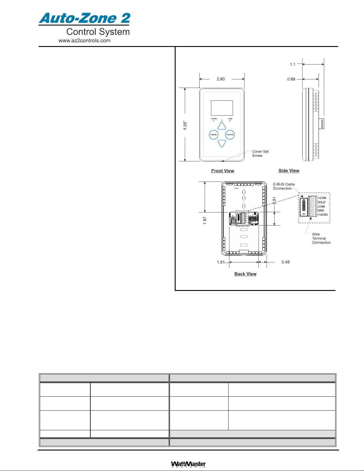
Form: AZ2-OE217-02-03-EBUS-DRS-1D.doc Page 1 of 1
Description
The OE217 series of Touch Screen E-BUS Digital
Room Sensors are used to sense Space Temperature
only or Space Temperature & Space Humidity. The
Space Temperature Sensor only model (OE217-02) is
used with the AZ 2 Main Controller, GPC-XP Controller
or the Zone/VAV Controller. The (OE217-03) model
senses both Space Temperature & Humidity and is
only used with the AZ 2 Main Controller or GPC-XP
Controller.
Besides sensing Temperature & Humidity, the E-BUS
Digital Room Sensors also provide these other useful
features:
• User Friendly Graphical LCD Display with LED
Backlight
• Display the Current Space and Outdoor Air
Temperature
• Display the Current Space Humidity and
Outdoor Air Relative Humidity (OE217-03 Model
Only)
• Display the current Zone Setpoint Temperature
• Equipped With Push Buttons for Changing the
Zone Setpoint Temperature
• Equipped With an Override Button for Forcing
the AZ 2 Main Controller into Occupied
Operation from Unoccupied Operation
• Provides graphics to indicate the mode of
operation
• Provides LEDs to indicate Schedule Override,
Button Push, and Alarms
The sensors connect to the AZ 2 Main Controller,
GPC-XP Controller or, Zone/VAV Controllers using E-
BUS cables connected between the controller and the
sensor or to the wire terminals using (4) conductor
cable. The E-BUS cables are available in multiple lengths to fit your job requirements. The E-BUS cables or (4) conductor
cable should not run in conduit with other AC line voltage wiring or with any conductors carrying highly inductive loads.
Mounting
The Digital Room Sensor is designed to be mounted to a vertical, 2” x 4” electrical box recessed in the wall. If the wall
cannot be penetrated, a plastic surface mount box such as those made by WiremoldTM, may be used to mount the
sensor to the wall surface. The Sensor is mounted by removing the front cover and fastening the housing base to the
electrical box using the supplied (2) 6/32” x 1” machine screws. The E-BUS cable is then plugged into the E-BUS
connector or the or (4) conductor cable is wired to the wire terminals. The cover is then placed onto the housing base
and the Allen Screw on the bottom of the base is adjusted to hold the cover in place.
OE217-02 & OE217-03 E-BUS
Digital Room Sensor
Technical Data OE217-02 & OE217-03 E-BUS Digital Room Sensor
Sensor Element Type III Thermistor 10k ohm
@ 77 F or Sensirion Device
Display 112 x 64 Monochrome Graphical LCD
w/LED Backlight
Sensor Reading
Range
40F to 120F
RH = 0-100%
Connection E-BUS Connector or
Wire Terminals
Ambient
Temperature
Limits
-40F to 180FWeight 3.2 oz.
Accuracy RH +/-3%, Temp +/- .8F
Three Year Warranty WattMaster reserves the right to change specifications without notice
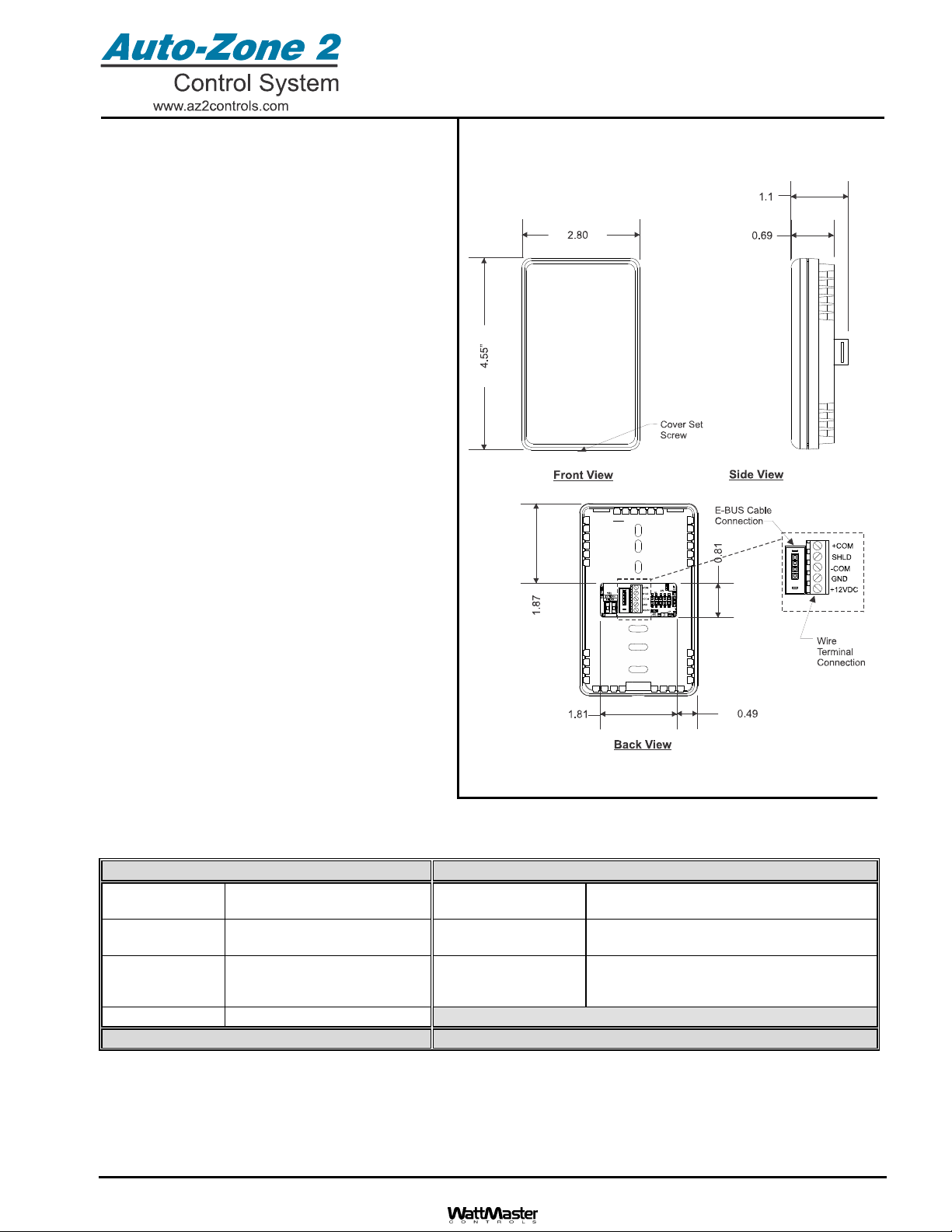
Form: AZ2-OE217-04-EBUS-DRS-1D.doc Page 1 of 1
Description
The OE217-04 E-BUS Digital Room
Temperature/Humidity Sensor Without Display is used
to sense Space Temperature & Space Humidity in
locations or applications where a display and its
associated features are not wanted or needed.
Because it has no display it does not have the
override, status or setpoint display capabilities that the
OE217-02 & OE217-03 have.
This sensor can be used with either the AZ 2 Controller
(OE630-23-AZ2) or the GPC-XP Controller (OE338-23-
GPCXP). It cannot be used with the Zone/VAV
Controllers (OE326-23D-AZ2 or OE326-23I-AZ2).
The sensors connect to the AZ 2 Main Controller, or
GPC-XP Controller using E-BUS cables connected
between the controller and the sensor or to the wire
terminals using (4) conductor cable. The E-BUS cables
are available in multiple lengths to fit your job
requirements. The E-BUS cables or (4) conductor
cable should not run in conduit with other AC line
voltage wiring or with any conductors carrying highly
inductive loads.
Mounting
The Digital Room Sensor is designed to be mounted
to a vertical, 2” x 4” electrical box recessed in the
wall. If the wall cannot be penetrated, a plastic
surface mount box such as those made by
WiremoldTM, may be used to mount the sensor to
the wall surface. The Sensor is mounted by
removing the front cover and fastening the housing
base to the electrical box using the supplied (2)
6/32” x 1” machine screws. The E-BUS cable is then
plugged into the E-BUS connector or the or (4)
conductor cable is wired to the wire terminals. The
cover is then placed onto the housing base and the
Allen Screw on the bottom of the base is adjusted to
hold the cover in place.
OE217-04 E-BUS Digital
Room Temp/Humidity Sensor
Without Display
Technical Data OE217-04 E-BUS Digital Room Temp/Humidity Sensor
Sensor Element Type III Thermistor 10k ohm
@ 77 F or Sensirion Device
Display None
Sensor Reading
Range
40F to 120F
RH = 0-100%
Connection E-BUS Connector or
Wire Terminals
Ambient
Temperature
Limits
-40F to 180FWeight 3.2 oz.
Accuracy RH +/-3%, Temp +/- .8F
Three Year Warranty WattMaster reserves the right to change specifications without notice
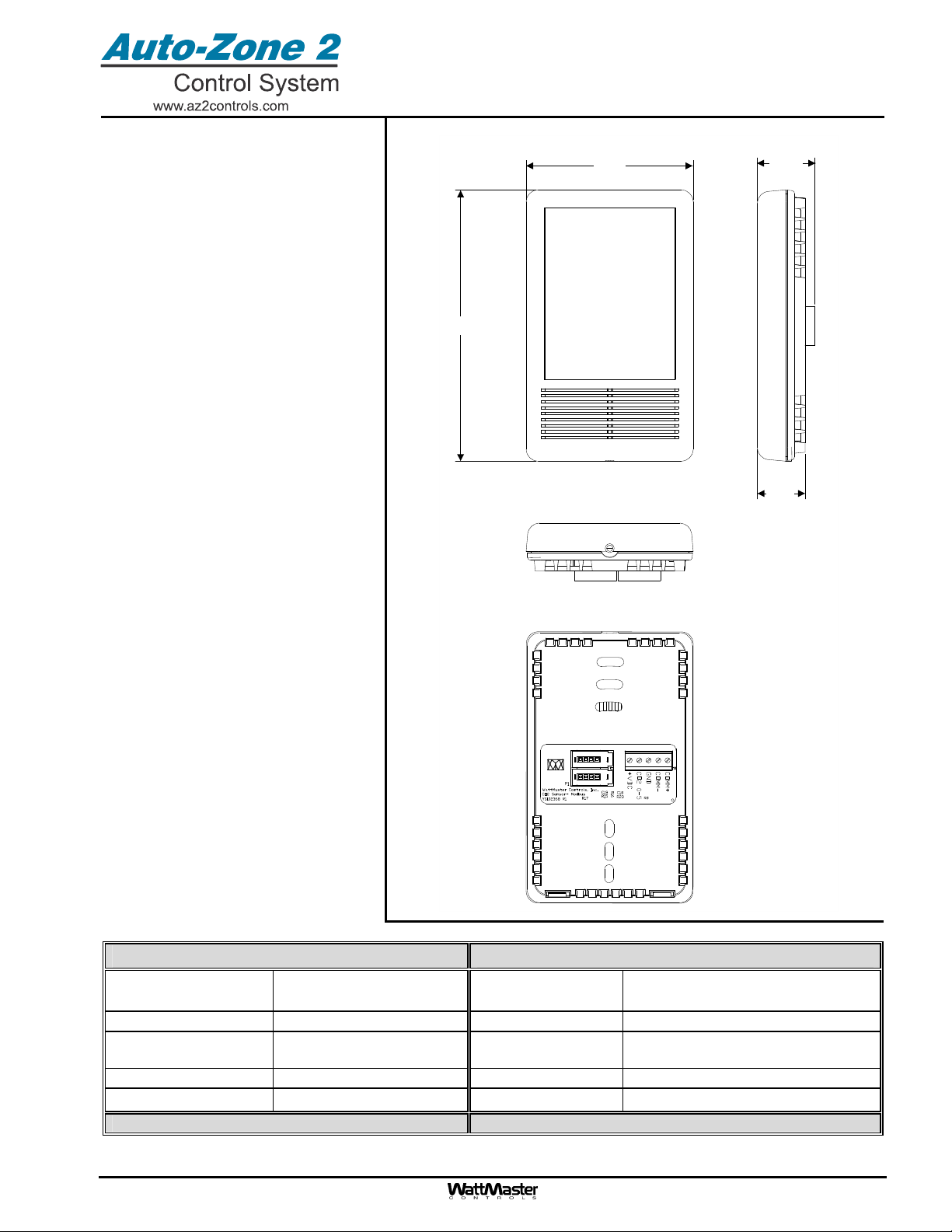
Form: AZ2-OE256-05—EBUS-CO2Sensor-1C.doc Page 1 of 1
Description
The Wall Mounted E-BUS CO2Sensor
(OE256-05) is used in conjunction with the
AZ 2 Controller (OE630-23-AZ2) or GPC-
XP Controller (OE338-23-GPCXP) to
monitor and control CO2levels in the
building environment.
Some typical applications are:
Demand Control Ventilation
Controlling ventilation in a building
where the occupancy varies
frequently
Controlling ventilation based on CO2
levels to ensure excess outside air
is not causing energy waste
To ensure good air distribution
throughout building zones
The OE256-05 is used for monitoring room
CO2levels and is designed for permanent
wall mounting in the conditioned space. It
connects to the AZ 2 or GPC-XP Controller
using an EBC E-BUS cable. It can be daisy
chained with the 217-02 E-BUS Digital
Room Temperature Sensor for applications
requiring both a room CO2sensor and
room temperature sensor.
The OE256-05 CO2 Sensor uses non-
dispersive infrared (NDIR) technology. The
CO2 Sensor’s accuracy is 50 ppm @1000
ppm or 2% of the measured value and has
a measurement range of 0-2000 ppm.
Mounting
The OE256-05 CO2 Sensor utilizes a sub-
base mounting plate with either terminal
blocks or E-BUS connection, providing for
quick and easy mounting and wiring. The
wall-mounted sensor’s sub-base is
compatible with standard junction boxes. A
locking screw secures the assembly to the
wall.
4.54
2.80 0.96
0.80
OE256-05 E-BUS Digital
CO2Sensor – Wall Mounted
Technical Data OE256-05 – CO2Sensor
Input Power 12-34 VDC Power Consumption 30 mW Maximum Average
1.25 W Peak Power
Operating Temperature 14to 122F Operating Humidity 5-95% RH Non-Condensing
Sample Method Diffusion Or Flow—through
50-100 ml/min Measurement Range 0 to 2000 ppm
Sensitivity <20 ppm Resolution 1 ppm
Analog Output 0-5 VDC Communications E-BUS
One Year Warranty WattMaster reserves the right to change specifications without notice
Form: AZ2-OE256-07-E-BUS-DUCT-CO2-01B.doc Page 1 of 1
Description
The Duct Mounted E-BUS Digital CO2Sensor is
used with the AZ 2 Controller (OE630-23-AZ2) or
the GPC-XP Controller (OE338-23-GPCXP) to
monitor and control Return Air CO2levels in the
building environment.
Some typical applications are:
Demand Control Ventilation
Controlling ventilation in a building where
the occupancy varies frequently
Controlling ventilation based on CO2
levels to ensure excess outdoor air is not
causing energy waste
To ensure good air distribution throughout
building zones
The OE256-07 is used for monitoring duct CO2
levels and is designed for permanent mounting in
the Return Air duct. It utilizes an aspiration box to
accurately capture CO2levels in the duct. It con-
nects to the AZ 2 or GPC-XP Controller by using
an E-BUS cable with E-BUS connectors.
The OE256-07 CO2 Sensor uses non-dispersive
infrared (NDIR) technology and has a measure-
ment range of 0-2000 ppm.
Mounting
The OE256-07 CO2 Sensor is housed in an aspi-
ration box. A conduit clamp is provided to help
seal the opening where the sensor cabling pene-
trates the aspiration box housing. The sensor has
an E-BUS connector for connecting it to the pro-
vided EBC E-BUS cable. The EBC E-BUS Cable
connects to the AZ 2 or GPC-XP Controller or E-
BUS Hub and then to the AZ 2 or GPC-XP Con-
troller. The sensor and aspiration box assembly
is mounted and secured to the ductwork with the
(2) supplied sheet metal screws. The remote
pickup tube assembly is mounted separately to
the ductwork by first cutting a 11/4” diameter hole
in the ductwork wall. The remote pickup tube is
then inserted into the hole. The remote pickup
tube is then secured to the ductwork by inserting (2) supplied sheet metal screws through the (2) mounting holes in the remote
pickup tube mounting plate and securing the remote pickup tube assembly by screwing it to the ductwork using a manual or
powered screw driver to tighten the screws. Using the supplied 10 ft. long tubing, connect the remote pickup tube to the aspi-
ration box assembly, cutting the tubing to fit.
432 1
3M
E-BUS CONNECTOR
FEMALE END
SENSOR
HOUSING
HINGED
COVER
BRASS BARB
FITTINGS FOR
0.170 I.D. TUBING
BRASS BARB
FITTINGS FOR
0.170 I.D. TUBING
EBC-10F
"WATTMASTER EBUS" "WATTMASTER EBU S"
EBC-10F
432 1
3M
432 1
3M
120.00” APPROX.
120.00” APPROX.
E-BUS CONNECTOR EXTENSION CABLE WITH MALE ENDS (PROVIDED WITH SENSOR)
0.170 I.D. TUBING
(
PROVIDED WITH SENSOR
)
FIRE RATED
CO2 PICKUP TUBE (PROVIDED WITH SENSOR)
CO2 SENSOR, HOUSINGAND CABLEASSEMBLY
5.00"
3.31"
4.12"
2.55”
13.00"
APPROX.
8.25" 0.55”
4.06"
2.81”
OE256-07 E-BUS Digital
CO2Sensor – Duct Mounted
Technical Data OE256-07 Duct Mounted E-BUS CO2Sensor
Input Power 12-34 VDC Power Consumption 30 mW Maximum Average
1.25 W Peak Power
Operating Temperature 14to 122FOperating Humidity 5-95% RH Non-Condensing
Sample Method Flow-Through
50-100 ml/min Measurement Range 0 to 2000 ppm
Sensitivity <20 ppm Resolution 1 ppm
Accuracy 50 ppm @ 1000 ppm
or 2% measured value Communications E-BUS
One Year Warranty WattMaster reserves the right to change specifications without notice
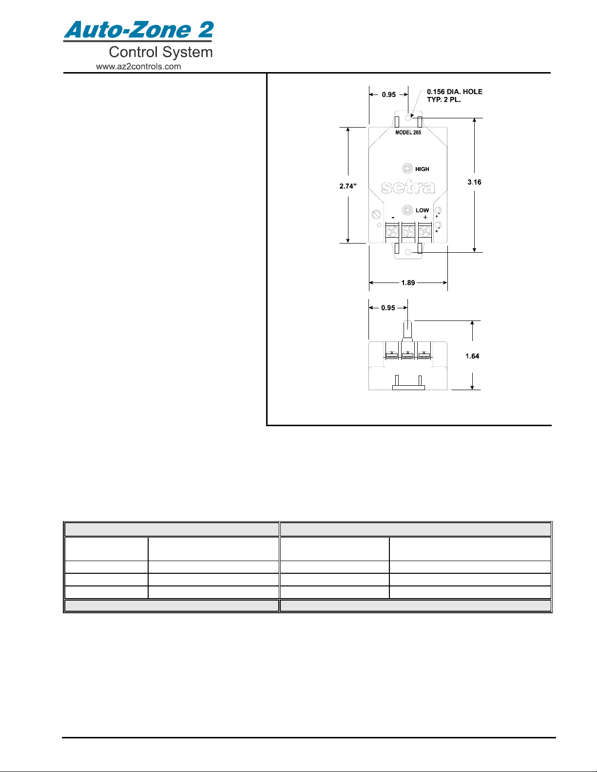
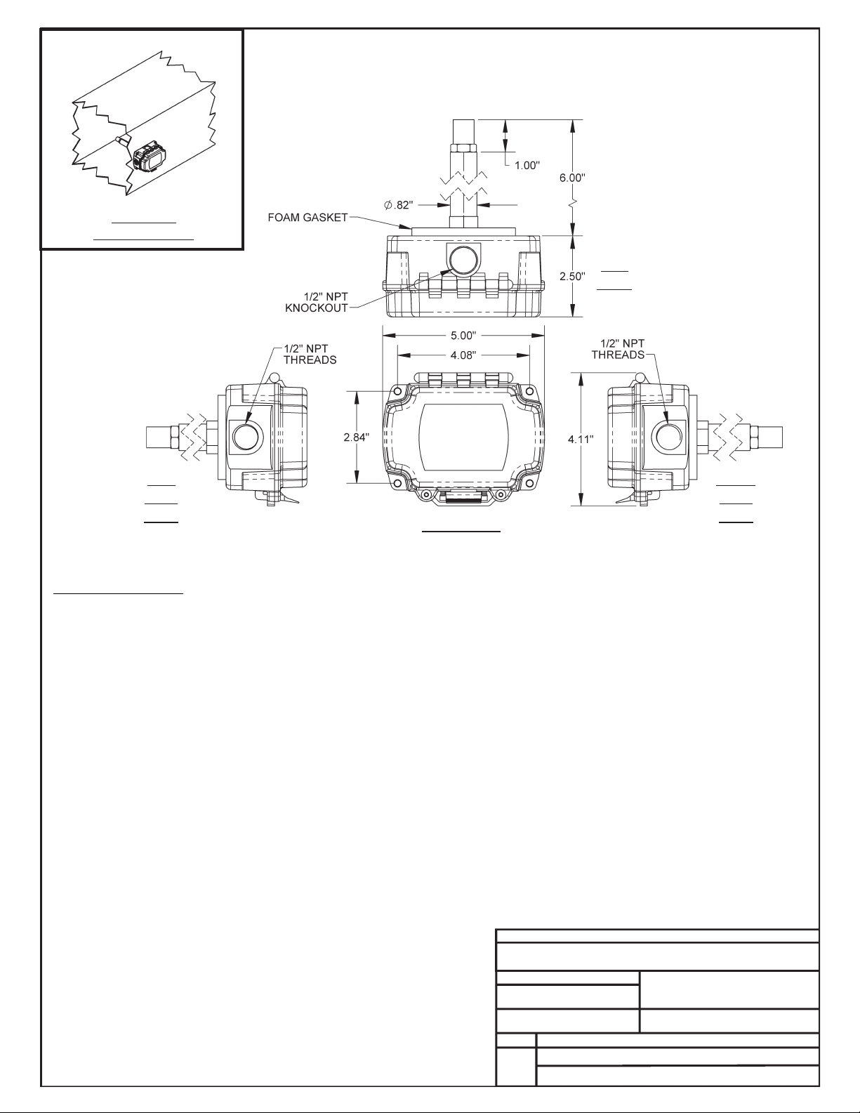
Form: AZ2-OE258-01-BPS-01B.doc Page 1 of 1
Description
The OE258-01 Building Static Pressure
Sensor is used to sense static pressure in
applications where monitoring of building
static pressure is required to insure the
building maintains the proper air
pressurization.
The OE258-01 Building Pressure Sensor
case is molded from fire retardant glass filled
polyester. The sensor utilizes a tensioned
stainless steel diaphragm and insulated
stainless steel electrode. This arrangement
allows up to 10 PSI overpressure without
damage to the unit. The sensor provides a
0.0 to 5.0 VDC output in response to a –0.25
to +0.25 inch WC pressure differential.
Accuracy is 1% of full scale of the sensor.
For easy wiring the OE258-01 Building
Static Pressure Sensor has (3) 6-32 screw
terminal wiring connectors. The sensor has
(2) ¼” barbed fittings provided for the
connection of tubing to the high and low
pressure ports.
The OE258-01 Static Pressure Sensor is
designed to be mounted to a flat surface by
means of the (2) 0.156 diameter holes
provided in the sensor casing. For accurate
readings the sensor must be mounted in a
vertical position.
OE258-01 Building Static
Pressure Sensor
Technical Data OE258-01 Building Static Pressure Sensor
Operating
Pressure Range -0.25” WC to +0.25” WC
Pressure Differential Power Input
Power Output 24 VDC
0 to 5 VDC
Operating Temp 0F to 150FHysteresis 0.1% of full scale
Circuit 3 Wire Non-repeatability
0.05% of full scale
Accuracy 1% of full scale Weight 3 ounces
Eighteen Month Warranty WattMaster reserves the right to change specifications without notice
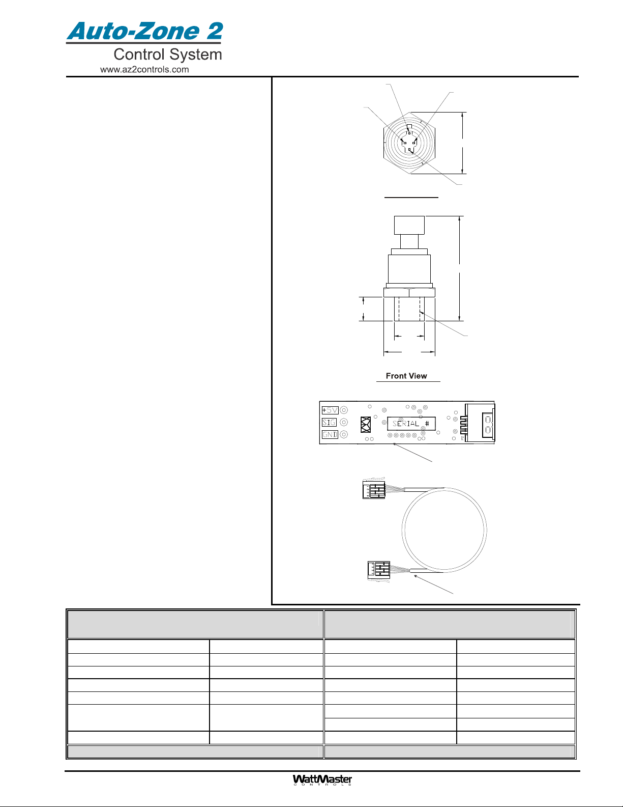
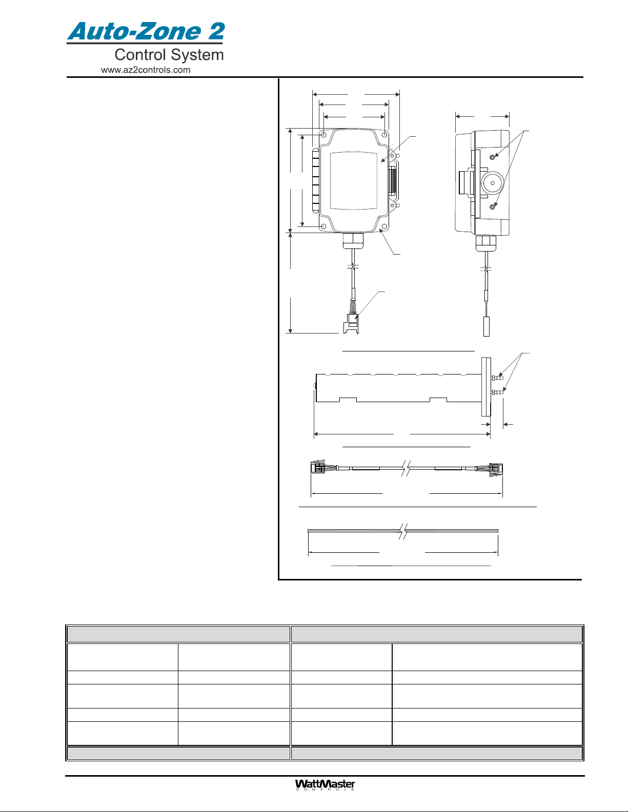
Form: AZ2-OE275-03-A-SuctPressSensorKit-1B.doc Page 1 of 1
Description
The OE275-03 Suction Pressure Transducer Kit
is comprised of the OE275-01 Suction Pressure
Transducer, an E-BUS Adapter Board, and a 3
foot EBC E-BUS cable. It is required for any AZ
2 Controller application with DX Cooling that
requires Dehumidification. The Suction
Pressure Transducer is used to measure
suction pressure at the HVAC unit’s DX
evaporator coil suction line. This suction line
pressure is converted to saturated refrigerant
temperature by the AZ 2 Controller. This
temperature is used by the AZ 2 Controller to
accurately control the compressors to provide
optimum performance from the system during
Dehumidification operation.
The Suction Pressure Transducer connects to
the E-BUS Adapter Board’s V, SIG, and GND
terminals through a cable. The cable is supplied
with a 3-pin Packard mating connector for
attachment to the sensor on one end and has 3
color-coded stripped wires on the other end.
The stripped wire ends can be spliced to other
wires to extend the wiring length when required.
The EBC E-BUS Cable connects to the E-BUS
Adapter Board. This cable must then connect to
the AZ 2 Controller directly or to an AZ 2
Expansion Board connected to the AZ 2
Controller.
The OE275-03 Suction Pressure Transducer’s
metal wetted parts are made from stainless
steel and Haynes 214 alloy. The Suction
Pressure Transducer is weather resistant.
Connection to the pressure source is
accomplished by screwing the 1/4” SAE female
Schrader fitting on the Suction Pressure
Transducer onto a 1/4” Schrader male valve
fitting (by others) that is welded into the suction
line. The Suction Line Transducer provides a
0.5 to 4.5 VDC output in response to a 0 to 250
PSIG pressure. Transducer accuracy is 0.25%
of the full scale of the transducer.
OE275-03
Suction Pressure Transducer Kit
Technical Data OE275-03 Suction
Pressure Transducer Kit
Operating Pressure Range -0 to 250 PSI Gauge Power Input 5 VDC
Operating Temp -40F to 185FSignal Output 0.5 to 4.5 VDC
Wetted Parts Construction Stainless Steel Electrical Cable Connection 3 Pin Packard Connector
Sensor Construction Haynes 214 Alloy Electrical Cable Length 3 Feet
Pressure Fitting Construction Stainless Steel Accuracy 0.25% of Full Scale
Pressure Fitting Size 1/4” SAE Female
Schrader Fitting Hysteresis 0.1% of Full Scale
Non-repeatability 0.05% of Full Scale
Weight 2.3 Ounces Response Time 0.05% of Full Scale
Three Year Warranty WattMaster reserves the right to change specifications without notice
2.18
0.50
0.63
1.28
1.06
1/4” SAE Femal
e
Schrader Fitting
Common
(Black)
Not Used
(Red)
+ Excitation
- Output
(White)
Top View
EBC E-BUS Cable
E-BUS Adapter Board
This manual suits for next models
1


