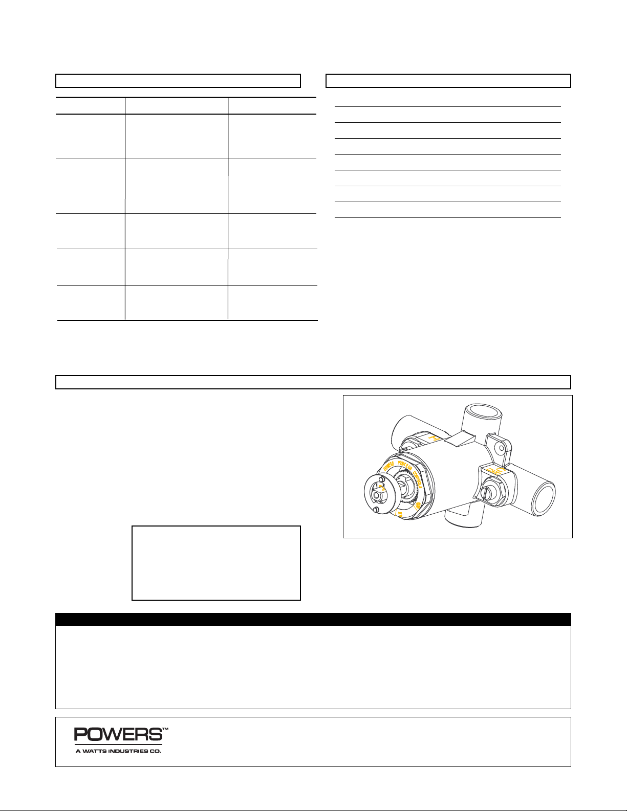
The BILTMORE is a pressure-balancing mixer which delivers
a predetermined mix of hot and cold water by compensating
for pressure fluctuations in the hot and cold water supplies.
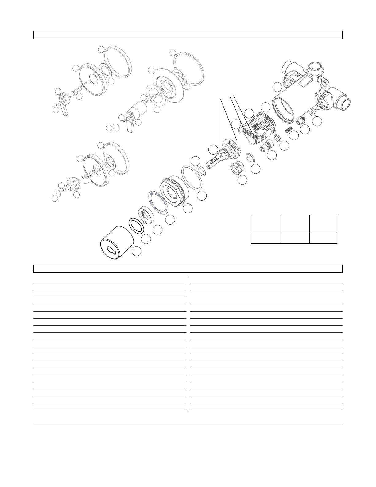
The BILTMORE features a poppet design valve as part of a
replaceable balancing cartridge. The poppet-type construc-
tion offers two distinct advantages: It will not stick due to lime
build-up or foreign particles in the supply water, and it has a
quick reaction time. The adjustable maximum temperature
stop prevents overadjustment of the handle.
Safety feature: Should either supply fail, the BILTMORE
closes either hot or cold supply water, to prevent a continued
spray of all hot or all cold water.
Capacity ..................................4.6 gpm @ 45 psi
[15 L/min @ 310 kPa Differential]
Maximum Static Pressure ..............125 psig [862 kPa]
Maximum Inlet Temperature..................180°F [82°C]
Inlet and Outlet Sizes ............1/2″sweat or NPT thread
Rough-in Guide ..................................All Models
Handle Rotation Stop............................All Models
Compliance .....................................ASSE 1016
Certified ..........................................CSA B125
The BILTMORE is particularly recommended for shower
and shower/tub installations in hotels, motels, high-rise
apartments, condominiums, and single-family housing.
Pressure balancing valve (Type P) senses incoming water
pressures and compensates for fluctuations in either to stabi-
lize outlet temperature (1). The entire balancing poppet assem-
bly is contained in a Celcon chamber (2). This chamber is
replaceable as a complete cartridge. The hot and cold are
mixed by the action of the mixing plate (3). As the temperature
adjustment stem is rotated from shutoff to maximum hot water
discharge temperature, the mixing plate passes the required
proportion of hot and cold water to produce the desired water
temperature. With the adjustment stem in its full clockwise
position, shutoff is obtained by closing off both supplies.
The maximum temperature limit stop (located on the bonnet)
allows the user to set the desired maximum discharge temper-
ature. This mixer does not compensate for supply water tem-
perature changes, so any variation in the water temperature
will affect the control point and the maximum discharge tem-
perature setting.
CAUTION: Maintenance of the unit requires resetting of
the maximum temperature adjustment stop. As inlet condi-
tions (pressures and temperatures) vary from site to site and
season to season, failure to properly adjust the maximum tem-
perature adjustment stop can result in excessive hot water
delivery.
TECHNICAL INSTRUCTIONS
BILTMORE Series 900
Pressure-Balancing Valves
Model 3
Form TI 900 v5
P902 P905
P909 P910
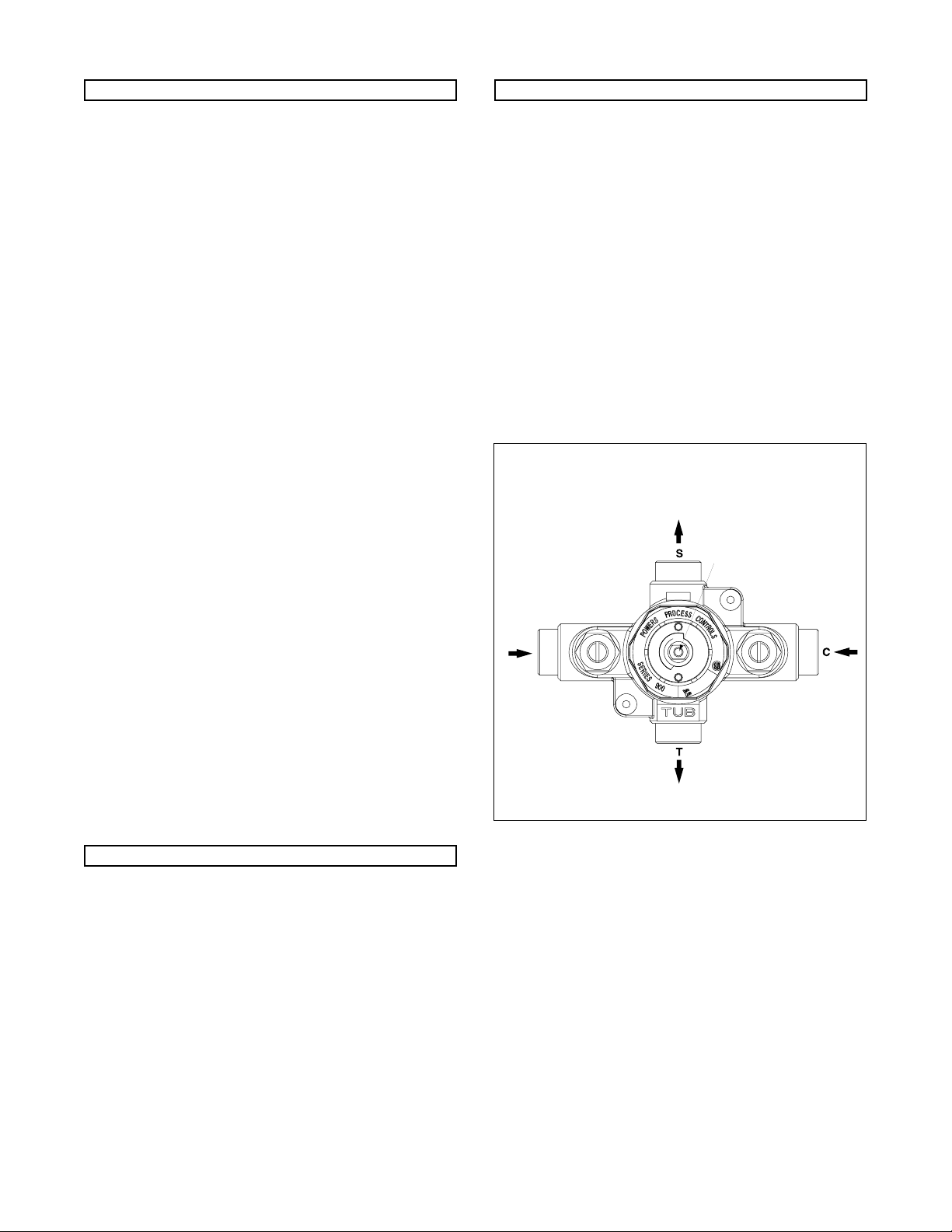
Figure 1 COLD WATER
SUPPLY
HOT WATER
SUPPLY
BALANCING
POPPETS
MIXING PLATE
OPERATION (See Figure 1)
APPLICATION
SPECIFICATIONS
DESCRIPTION