wattsonic 6.0K-25A-3P User manual
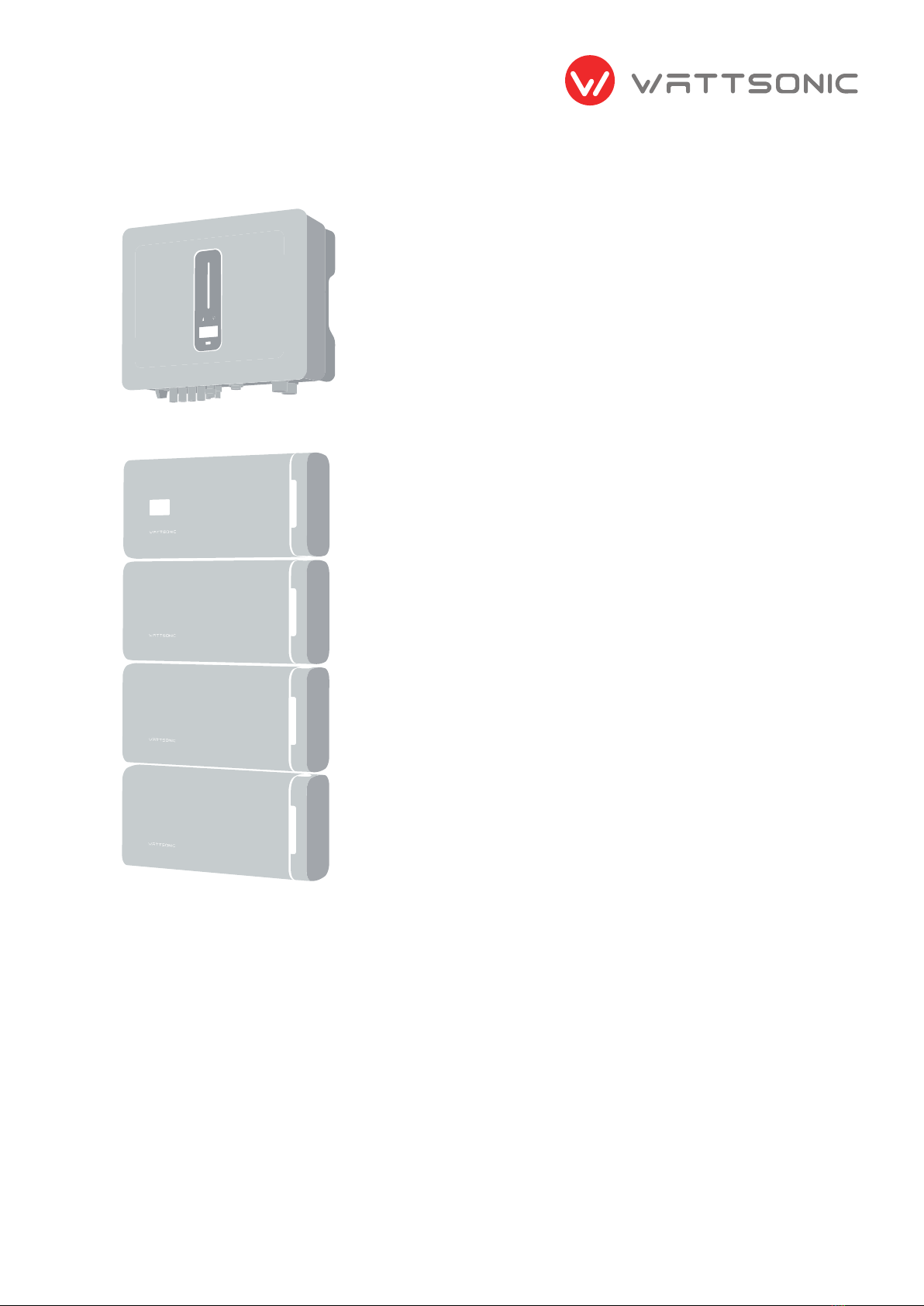
4/5/6/8/10/12 KW-25A-3P | 10/12/15/20 KW-40A-3P
Wattsonic High Voltage Three Phase All-In-One ESS
Oct 2023
User Manual


Power your home,
and you will power the planet.

Contents
1
2
3
4
5
6
7
Safety Instructions
and Warning
Introduction
Before Using
Overview Description
Product
Mechanical Installation
3.1 How to use this manual
3.2 Target groups
3.3 Supported environment
3.3.1 Installation location
3.3.2 Installation location of batteries
3.3.3 Installation angle
3.3.4 Recommended installation spacing
3.4 Disclaimer
2.1 What's wattsonic all-in-one ess
5.1 System introduction
5.2 Product introduction
5.2.1 Models
5.2.2 Specications
5.2.3 BMS appearance
5.2.4 Battery appearance
5.2.5 Combiner boxappearance
5.3 Operation modes
5.4 Back-up and off-grid output
5.6 Unpacking and storage
6.1 Mounting the inverter
6.2 Mounting batteries
6.2.1 Wall mounted (vertical)
6.2.2 Battery stack mounted
Electrical Connection
7.1 Earth cables connection
7.2 Battery cables connection
7.2.1 Wall mounted (vertical) of single string system
7.2.2 Wall mounted (vertical) of multi-string system
7.2.3 Stack mounted of single string system
7.2.4 Stack mounted of multi-string system
7.3 Inverter connection
7.3.1electrical wiring diagram
6
7
7
7
7
7
8
8
8
9
9
10
23
25
26
27
29
30
30
31
33
34
36
36
13
14
14
14
16
16
16
17
22
22
10
13
23
29

8
9
10
11
12
72
75
76
58
58
58
71
71
71
77
78
86
58
71
77
60
72
Commissioning
Screen Operation
Monitoring
Troubleshooting
Appendix
8.1 App preparation
8.2 Inspection before commissioning
8.3 Commissioning procedure
9.1 Main window
9.2 General setting
9.3 Advanced setting
9.4 Country code (safety code) setting
9.5 Auto-test
9.6 Reactive power
9.6.1 “Off” modes
9.6.2 “Pf” mode
9.6.3 “Qt” mode
9.6.4 “Q(p)” mode
9.6.5 “Q(u)” mode
10.1 Monitoring device
10.2 Cloud monitoring app
10.3 Local conguration app
11.1 Error message
11.2 Inverter maintenance
11.3 Battery maintenance
12.1 Master BMS& battery datasheets
12.2 Inverter datasheets
12.3 Contact Information
60
61
63
66
66
68
68
68
69
69
70
7.4 Ac connection
7.4.1 Ac side requirements
7.4.2 Assembling the ac connector
7.4.3 Installing the ac connector
7.5 Monitoring device installation
7.6 Meter and CT connection
7.7 Communication connection
7.7.1 Assembling the Multi-Com connector
7.7.2 Connect the meter and bms communication cables
7.7.3 Connect other cables
7.7.4 Installing the com connector
7.7.5 Meter and bms communication
7.7.6 Ems communication
7.7.7 Dred
7.7.8 Multifunction relay
7.7.9 Parallel system
7.8 Pv string connection
7.8.1 Pv side requirements
7.8.2 Assembling the pv connector
7.8.3 Installing the pv connector
7.9 The power cable of the battery connection
7.9.1 The following principles must be considered
when making battery connection
7.9.2 Assembly procedures of the lithium battery
connector
7.10 System start and stop
7.10.1 Start the system
7.10.2 Stop the system
7.10.3 Emergency stop function
39
39
40
42
42
42
43
44
45
46
47
47
48
48
48
50
51
51
52
53
54
54
54
56
56
56
57
User Manual
6
Overview
Warning: Before installing or using the Wattsonic Li-LV LiFePO4 battery modules, read this document. Failure to
do so or to follow any of the instructions or warnings in this document can result in electrical shock, serious injury,
death, or damage to the Wattsonic Li-LV LiFePO4 battery modules, potentially rendering them unusable.
To secure the full 10-year product warranty, be sure to install the Wattsonic Li-LV battery modules by qualied installers.
Product specications
All specications and descriptions in this document are veried to be accurate when printed. However, because
continuous improvement is a goal at Wattsonic, we reserve the right to make product modications at any time.
The illustrations in this document are solely for demonstrative purposes. Details may appear slightly different depending
on the product version and market region.
Errors or omissions
To communicate any inaccuracies or omissions in this manual, please send an email to : service@wattsonic.com
ELECTRONIC DEVICE: DO NOT THROW AWAY
Proper disposal of batteries is required. Refer to your local codes for disposal requirements.
(ie. EC N 1013/2006 among European Union).
©2023 Wuxi Wattsonic Energy Technology Co., Ltd.
All rights reserved.
All information in this document is subject to copyright and other intellectual property rights of Wuxi Wattsonic
Energy Technology Co., Ltd. and its licensors. This material may not be modied, reproduced or copied, in whole or in
part, without the prior written permission of Wuxi Wattsonic Energy Technology Co., Ltd. and its licensors. Additional
information is available upon request. The following are trademarks or registered trademarks of Wuxi.
All other trademarks contained in this document are the property of their respective owners and their use herein does
not imply sponsorship or endorsement of their products or services. The unauthorized use of any trademark displayed
in this document or on the product is strictly prohibited.
Wattsonic Energy Technology Co., Ltd. in Jermany, South Africa,
Australia, UK and other countries:

User Manual
7
Introduction
2.1 What's wattsonic all-in-one ess
The future of sustainable energy
Wattsonic All-in-One ESS is an intelligent hybrid energy storage system that turns solar panels into an all-day resource
while offering backup power during a grid outage. It enables renewable energy storage, allowing optimized home
energy control and increasing total electricity production from renewable sources. Reliable renewable energy improves
the resiliency of the grid, reduces energy costs, and increases the impact of electric vehicle ownership.
Power when needed
Wattsonic All-in-One ESS enables energy storage from solar panels during the day or from the grid when energy rates
are low, discharges energy for backup or use at night, and automatically optimizes home energy. Wattsonic All-in-One
ESS thereby maximizes solar consumption and reduces energy spending.
A exible solution
Wattsonic All-in-One ESS can be charged from solar or grid power, providing backup power.
If more energy is needed, multiple Wattsonic All-in-One ESSs can be installed together to work as a more extensive
system.
This manual is an integral part of Wattsonic 4.0–20.0 kW-3P series three-phase high-voltage hybrid inverters (after this
referred to as the inverter). It mainly introduces assembly, installation, electrical connection, debugging, maintenance,
and troubleshooting of the products.
The products, services, or features purchased are subject to the commercial contracts and terms of Wuxi Wattsonic
Energy Technology Co., Ltd., All or part of the products, services, or features described in this document may not be
within the purchase scope. This document serves only as a guide; all statements, information, and recommendations do
not constitute any express or implied guarantee.
Before Using
3.1 How to use this manual
3.2 Target groups
Before installing and using inverters, please read this manual carefully, understand the safety information, and be familiar with
the functions and characteristics of inverters.
The manual content of subsequent inverter versions may be subject to change. You can nd the newest manual at www.
wattsonic.com.
This manual applies to electrical installers with professional qualications and end-users, who should have the following skills:
a) Training for installation and commissioning of the electrical system, as well as dealing with hazards.
b) Knowledge of the manual and other related documents.
c) Knowledge of the local regulations and directives.

User Manual
8
3.3 Supported installation environment
1. The wall on which the inverters are mounted must withstand the weight of the inverter.
2. The inverter needs to be installed in a well-ventilated environment.
3. Do not expose the inverter directly to strong sunlight to prevent excessive temperature operation. You can install the
inverter in a place with shelter to avoid direct exposure to sunlight and rain.
4. Install the inverter at eye level for easy inspection of screen data and further maintenance.
5. Install the inverter at a place convenient for electrical connection, operation, and maintenance.
6. The ambient temperature of the inverter installation location should be between -30°C and 60°C.
7. The surface temperature of the inverter may reach up to 75. To avoid the risk of burns, do not touch the inverter while
it's operating, and you will need to install the products out of the reach of children.
3.3.1 Installation location of inverters
3.3.2 Installation location of batteries
The oor is at and level.
There are no ammable or explosive materials.
The ambient temperature is within the range of 0 to 50.
The temperature and humidity remain constant.
There is minimal dust and dirt in the area.
The distance from a heat source is more than 2 meters.
The distance from the air outlet to the system is more than 0.5 meters.
Do not cover or wrap the battery case or cabinet.
Do not place it in a children's or pet-touchable area.
The installation area shall avoid direct sunlight.
There are no mandatory ventilation requirements for the battery module, but please avoid installation in a conned
area(minimum 300mm to top/left/right/front).
The aeration shall avoid high salinity, humidity, or temperature.
Keep ammable and combustible things away from the inverter
Recommended installation location
Correct
Wrong

User Manual
9
Install the inverter vertically. Never install the inverter horizontally, at a forward or backward tilt, or upside down.
3.3.3 Installation angle
3.3.4 Recommended installation spacing
Permitted and prohibited mounting positions Correct Wrong
Reserve enough clearance around the inverter to ensure sufcient space for heat dissipation.
Recommended installation spacing
Minimum
300mm
to left space
Minimum
300mm
to right space
Minimum 500mm
to top space
Minimum
300mm
Minimum
70mm
Minimum
300mm
User Manual
10
3.4 Disclaimer
Wuxi Wattsonic Energy Technology Co., Ltd. has the right not to undertake quality assurance in any of the following
circumstances:
1) Damages caused by improper transportation
2) Damages caused by incorrect storage, installation, or use
3) Damages caused by the installation and use of equipment by non-professionals or untrained personnel
4) Damages caused by failure to comply with this document's instructions and safety warnings
5) Damages of running in an environment that does not meet the requirements stated in this document
6) Damages caused by operation beyond the parameters specied in applicable technical specications
7) Damages caused by unauthorized disassembly, alteration of products, or modication of software codes
8) Damages caused by an abnormal natural environment (force majeure, such as lightning, earthquake, re, storm, etc.)
9) Any damages caused by the process of installation and operation that don't follow the local standards and regulations
10) Products beyond the warranty period
Safety Instruction and Warning
Wattsonic All-in-One ESS, installation, and repair instructions assume knowledge of high-voltage electricity. Wattsonic
Certied installers should only perform them. Wattsonic assumes no liability for injury or property damage due to repairs
attempted by unqualied individuals or a failure to follow these instructions properly. When utilizing Wattsonic ESS, you
have to follow these warnings and precautions.
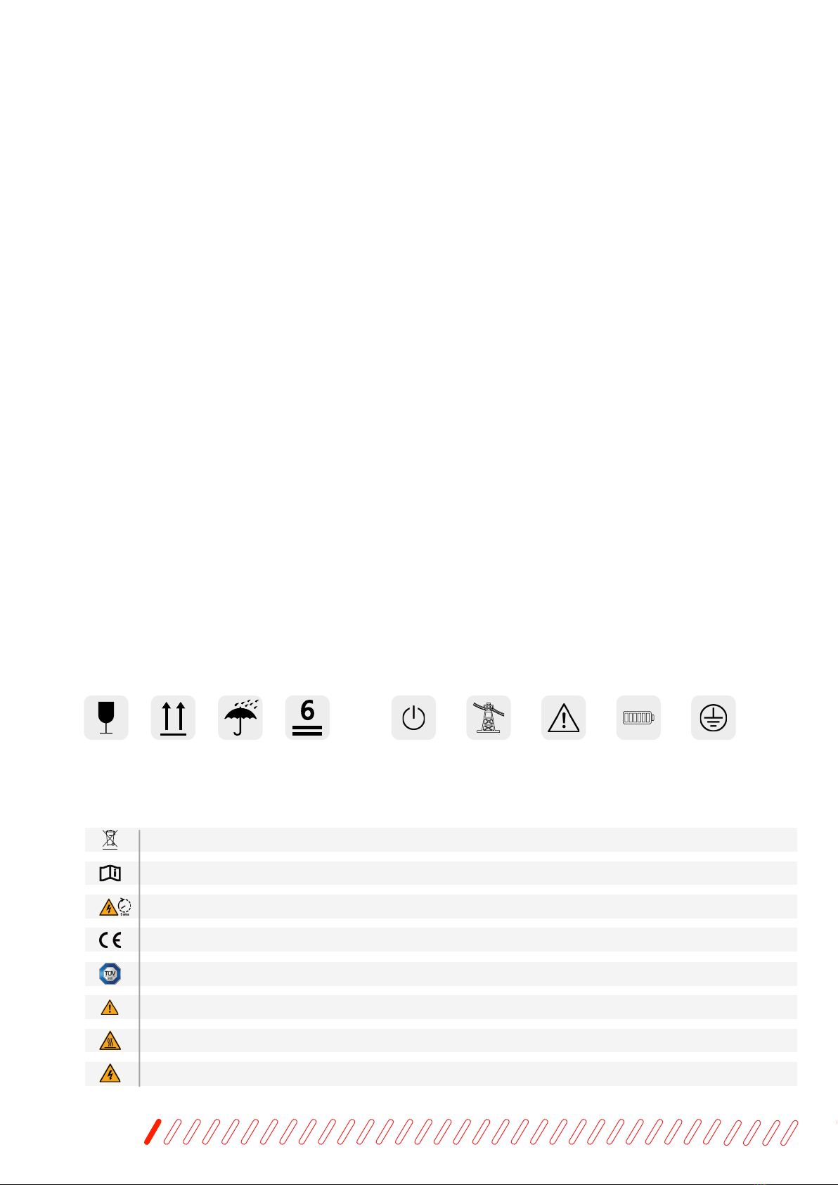
Symbols on the packing box Symbols on the hybrid inverter
Symbols on the Inverter nameplate
PLEASE SAVE THESE ESSENTIAL SAFETY GUIDELINES.
Handle
with care.
This side up. Keep dry. Stacked layers. Power
indicator.care. Grid status
indicator. Inverter status
indicator. Battery SOC
indicator. Grounding symbol:
The inverter casing
needs to be proper-
ly grounded.
The inverter cannot be disposed of with household waste.
Please read the instructions carefully before installation.
Do not touch any internal parts of the inverter until 5 min after being disconnected from the mains and PV input.
CE mark, the inverter complies with the requirements of the applicable CE guidelines.
TUV certication.
Danger. Risk of electric shock!
The surface is hot during operation and no touch is allowed.
Electric shock hazard: Using a person to disassemble the inverter casing is strictly forbidden.

User Manual
11
Symbols in this document
This manual uses the following symbols to highlight important information:
1. Before installation, please read this manual carefully and follow the instructions in this manual strictly.
2. Installers must undergo professional training or obtain electrical-related professional qualication certicates.
3. Do not open the front cover of the inverter when installing. Apart from performing work at the wiring terminal (as
instructed in this manual), touching or changing components without authorization may cause injury to people, damage
to inverters, and annulment of the warranty.
4. All electrical installations must conform to local electrical safety standards.
5. If the inverter needs maintenance, don't hesitate to contact the local designated personnel for installation and
maintenance.
6. To use this inverter for power generation needs the permission of the local power supply authority.
7. The temperature of some parts of the inverter may exceed 60° C during operation. To avoid being burnt, do not touch
the inverter during the process. Let it cool before touching it.
8. When exposed to sunlight, the PV array generates dangerous high DC voltage. Please operate according to our
instructions, or it will endanger your life.
9. When wiring the lithium battery terminals, please disconnect the breaker or switch of the lithium battery in case of a
physical injury caused by the high voltage.
Safety Notes
DANGER
WARNING
CAUTION
ATTENTION
NOTE
Danger signs warn of urgent, dangerous situations. If not avoided, it could result in death
or serious personal injury.
Warning indicates a hazardous situation that, if not avoided, could result in injury or death.
Caution indicates a hazardous situation that, if not avoided, could damage the equipment.
Attention transmits safety warning information about equipment or the environment,
data loss, or other unpredictable results. It does not relate to physical injury.
Note indicates a vital step or tip that leads to the best results but is not safety or damage-
related.
1. Read this entire document before installing or using Wattsonic All-in-one ESS. Failure to do so or to follow
any of the instructions or warnings in this document can result in electrical shock, serious injury, or death or
can damage the Wattsonic LFP Battery, potentially rendering it inoperable.
2. A battery can present a risk of electrical shock, re, or explosion from vented gases. Observe proper precautions.
3. Wattsonic All-in-one storage system installation must be carried out only by Wattsonic Certied Installers, trained
in dealing with high voltage electricity.
4. Wattsonic is heavy and challenging to lift.

User Manual
12
1. Do not use cleaning solvents to clean Wattsonic LFP Battery or expose Wattsonic LFP Battery to
ammable or harsh chemicals or vapors.
2. Do not use uids, parts, or accessories other than those specied in this manual, including non-genuine
Wattsonic parts or accessories or parts or accessories not purchased directly from Wattsonic or a Wattsonic-
certied party.
3. Do not place Wattsonic LFP Battery in a storage condition for more than one (1) month or permit the electrical
feed on the Wattsonic LFP Battery to be severed for more than one (1) month without placing Wattsonic LFP Battery
into a storage condition under Wattsonic’s storage specications.
4. Do not paint any part of Wattsonic LFP Battery, including any internal or external components such as the exterior
shell or casing.
5. Do not directly connect the Wattsonic LFP Battery to photovoltaic (PV) solar wiring.
6. When installing a Wattsonic LFP Battery in a garage or near vehicles, keep it out of the driving path. Install the
Wattsonic LFP Battery on a side wall and/or above the height of vehicle bumpers.
1. Install Wattsonic LFP Battery at a height that prevents damage from ooding.
2. Operating or storing Wattsonic LFP Battery in temperatures outside its specied range might cause
damage to Wattsonic LFP Battery.
3. Do not expose the Wattsonic LFP Battery to ambient temperatures above 60°C (140°F) or below -30°C (-22°F).
Ensure no water sources are above or near Wattsonic LFP Battery, including downspouts, sprinklers, or faucets.
Environmental conditions
5. Use the Wattsonic LFP Battery only as directed.
6. Do not use a Wattsonic LFP Battery if it is defective, appears cracked, broken, or otherwise damaged, or
fails to operate.
7. Before beginning the wiring portion of the installation, power off the inverter and then open the AC and DC
disconnect switches (if applicable).
8. Do not attempt to open, disassemble, repair, tamper with, or modify Wattsonic LFP Battery. Wattsonic LFP
Battery is not user serviceable. LFP Cells in Wattsonic Battery are not replaceable. Contact the Wattsonic
Authorized Reseller who sold the Wattsonic LFP Battery for any repairs.
9. Do not connect Wattsonic LFP Battery to alternating current carrying conductors. Wattsonic All-in-one
storage system including battery and inverter must be wired to either an inverter or a DC combiner panel that is
then wired to an inverter. No other wiring conguration may be used.
10. Wattsonic LFP Battery contains components, such as switches and relays, that can produce arcs or sparks.
11. Handle with care to protect the Wattsonic LFP Battery and its components from damage when transporting.
Do not impact, pull, drag, or step on Wattsonic LFP Battery. Do not subject Wattsonic LFP Battery to any
muscular force. To help prevent damage, leave Wattsonic LFP Battery in its shipping packaging until it is ready to
be installed.
12. Do not insert foreign objects into any part of Wattsonic LFP Battery.
13. Do not expose Wattsonic LFP Battery or its components to direct ame.
14. Do not install Wattsonic LFP Battery near heating equipment.
15. Do not immerse Wattsonic LFP Battery or its components in water or other uids.
User Manual
13
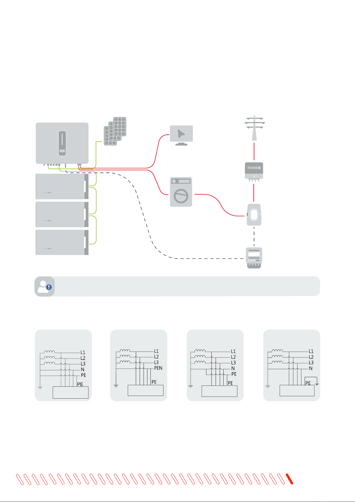
Description
The hybrid solar system usually comprises the PV array, hybrid inverter, lithium battery, loads, and power grid.
5.1 System introduction
PV modules
Battery
Back up load
On-grid load
Hybrid Inverter
Current
transformer
Utility meter
for billing
pureposes
Smart
meter
Utility Grid
The system is not suitable for supplying life-sustaining medical devices. It cannot guarantee backup power
in all circumstances.
The applicable grid types for the Wattsonic 4.0-20.0kW-3P series are TN-S, TN-C, TN-C-S, and TT. When applied
to the TT grid, the voltage of N to PE suggests less than 30V.
TN-S
4.0~20.0KW-3P
Tranformer
TN-C
4.0~20.0KW-3P
Tranformer
TN-C-S
4.0~20.0KW-3P
Tranformer
TT
4.0~20.0KW-3P
Tranformer
User Manual
14
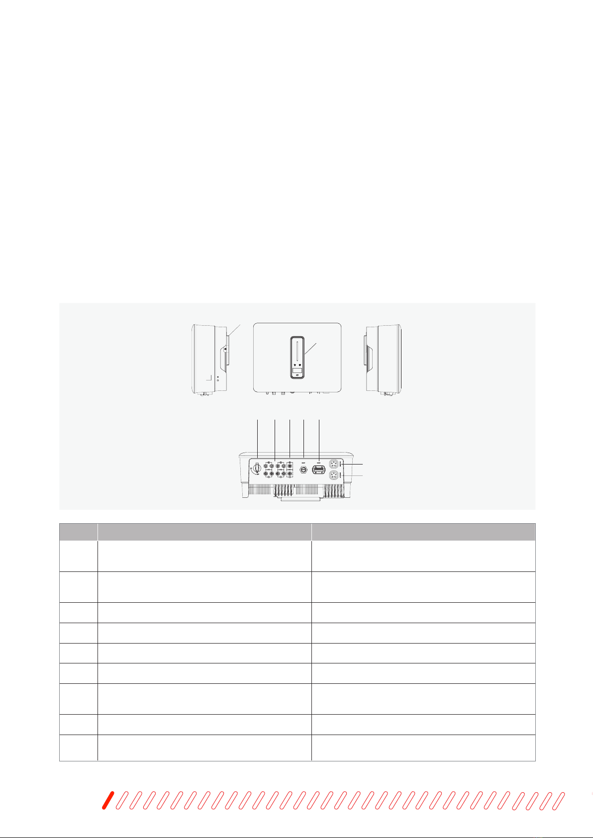
5.2.1 Models
5.2.2 Inverter appearance
1. The Wattsonic 4.0-20.0kW-3P series hybrid inverter includes 10 models, which are listed below: 4.0K-25A-3P,
5.0K-25A-3P, 6.0K-25A-3P, 8.0K-25A-3P, 10K-25A-3P, 12K-25A-3P, 10K-40A-3P, 12K-40A-3P, 15K-40.0A-3P, 20K-40A-
3P.
2. The Wattsonic Li-HV BMS includes 2 models,
which are BMS-2.3, BMS-3.84.
3. The Wattsonic Li-HV battery module includes 2 models,
which are WTS-R24-2.3kWh, WTS-R24-3.84kWh.
For detialed datasheet, pleace refer to chapter 12: Appendix.
1
2
34 5 6 7
8
9
Item Terminal Note
1 Display and LED panel Display the operation information and working
status of the inverter.
2 Hanger Used to hang the inverter on the wall-mounting
bracket.
3 DC switch Used to safely disconnect the DC circuit.
4 DC input terminal PV connector
5 Battery input terminal Battery connector
6 COM1 port WiFi/LAN/4G module connector
7 COM2 port Multi-function Connector (Meter/BMS/RS485/
DRED)
8 On-grid output terminal Used for On-grid output cable connection
9 Back-up output terminal Used for Back-up output cable connection
The Wattsonic 4.0-20.0kW-3P series inverter is also known as a hybrid inverter or storage inverter, which is mainly used
to combine the PV array, lithium battery, loads, and power grid to realize intelligent power management and dispatching.
5.2 Product introduction

User Manual
15
1
23
4
5
Item Indicator Status Description
1Power and Alarm
Indicator
Off No power.
Blue
Quick ashing Inverter entered self-test status.
Slow ashingvvvv Inverter entered waiting status.
Breathe ashing Inverter works normal.
Orange Breathe ashing
Low battery warning, the battery
power is about to reach the SOC
protection value.
Red Always on An alarm or fault is detected, view
the fault info on the display.
2Grid
Indicator
Off Grid lost.
Slow ashing Inverter detected grid but not running in on-grid mode.
Always on Inverter works in on-grid mode.
3Communication
Indicator
Green Always on The inverter communication is
running normally.
Green Flashing
The inverter communicates with
EMS or Master inverter through
RS485 or CAN.
Orange Always on The inverter isn’t communicating
with Wattsonic smart meter.
Red Always on The inverter isn’t communicating
with the BMS.
4 Display Display off to save power, press the button to wake up the display.
5 Button Switch display information and set parameters by short press or long press.

User Manual
16
5.2.3 BMS appearance
5.2.4 Battery appearance
5.2.5 Combiner box appearance
ON
OFF
IOT Battery COM
Battery Input
LAN COM
Parallel COM
Inverter/Parallel COM
Inverter
WIFI
ON
OFF
IOT Battery COM
Battery Input
LAN COM
Parallel COM
Inverter/Parallel COM
Inverter
WIFI
Emergency Stop
Batte-
Batte+
Batte Stop Inveer Stop
User Manual
17
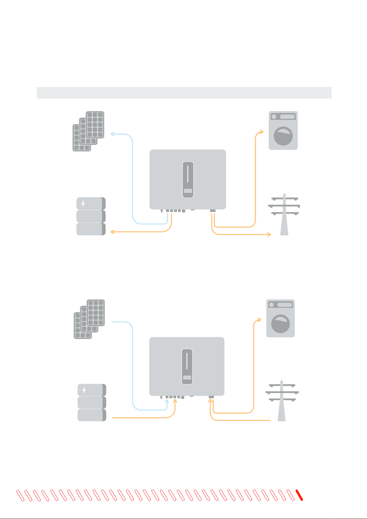
5.3 Operation modes
Wattsonic 4.0-20.0kW-3P series inverter has the following basic operation modes and you can congure the operation
mode as per your preference in the App.
General Mode
In this working mode, when the power from the PV array is sufcient, PV power will supply the loads, battery, and grid
in the order of loads rst, battery second, and grid last.
(You can set the power to the grid to 0W when the local grid doesn’t allow inverter power to feed to the grid).
When the PV power is insufcient, the battery will discharge to supply loads, and the grid will join in if the battery is
not enough to supply loads.
PV
Battery
Loads
Inverter
Grid
PV
Battery
Loads
Inverter
Grid

User Manual
18
Peak load Shifting (Load Shifting)
Set the maximum power Pmax (kVA) contracted with the grid.
When the load consumption is less than the Pmax, the PV will charge the battery rst, and the grid will supply the
load. Once the battery is complete, the PV will power the load and the grid rather than the battery.
When the load consumption exceeds the Pmax, the inverter will take power from the battery and PV to supply power
to the load to compensate for the power that exceeds the Pmax.
*To realize the “Peak load Shifting” function, the load power that exceeds Pmax has to be within the inverter max output
power. Otherwise, the inverter will only output the maximum power allowed.
PV
Battery
Loads
Inverter
Pload>Pmax
Grid
PV
Battery
Loads
Inverter
Pload>Pmax
Grid

User Manual
19
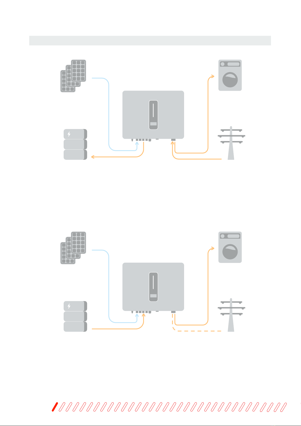
UPS Mode
In this working mode, the inverter will use the power from PV or grid to charge the battery until it is fully charged, and
as long as the grid is there, the battery won’t discharge.
When the grid fails, power from the PV and battery will supply loads connected to the backup side (UPS).
PV
Battery
Loads
Inverter
Grid
PV
Battery
Back-up Loads
Inverter
Grid
User Manual
20
Economic Mode
In this working mode, you can set charge/discharge power and time in the App. The inverter will use the energy from
PV or the grid (whether to use it or not can be set in the App) to charge the battery for a predetermined period.
The inverter will use power from PV and batteries to supply loads for the predetermined period, and the grid will
deliver the insufcient part.
PV
Battery
Loads
Inverter
Grid
PV
Battery
Loads
Inverter
Grid
This manual suits for next models
8
Table of contents
Other wattsonic Inverter manuals


Popular Inverter manuals by other brands


WhisperPower
WhisperPower 12-2000 user manual

MasterPower
MasterPower Omega ESS 5.5KW user manual

FRONIUS
FRONIUS Signal Card Operating and installation instructions

Compu Pool Products
Compu Pool Products Infinity Series Installation and operation manual

Sofar solar
Sofar solar HYD 5- 20KTL-3PH Series user manual

KEBCO
KEBCO COMBIVERT G6 Safety manual

FRONIUS
FRONIUS Symo Hybrid 3.0 installation instructions

FRONIUS
FRONIUS 10.0-3 208-240 installation instructions

FRONIUS
FRONIUS Symo Hybrid 3.0-3-S Installation instruction

MaxPower
MaxPower Sunglow VMII 3000 user manual

OutBack Power
OutBack Power GSLC175-AC-120 quick start guide

MQ Power
MQ Power EGC1000C Specifications