wattsonic 4.0K-25A-3P User manual
4/5/6/8/10/12KW-25A-3P
10/12/15/20KW-40A-3P
User Manual
Wattsonic Gen3 Hybrid Inveer

CONTENTS

CONTENTS
………………………………………………………………………… 6
………………………………………………… 7
…………………………………………… 10
……………………………………………………… 11
………………………………………………………………… 11
………………………………………………………………………… 11
………………………………………………………………… 13
……………………………………………………………………… 13
………………………………………………………… 15
………………………………………………………… 16
……………………………………………………… 18
……………………………………………………………… 19
……………………………………………… 24
……………………………………………………… 25
………………………………………………………………………… 27
………………………………………………………… 29
…………………………………………………………………… 32
………………………………………………………… 33
5.3 ……………………………………………………… 34
………………………………………………………… 34
………………………………………… 35
………………………………………………………………… 35
…………………………………………………………… 36
………………………………………… 37
…………………………………………………… 37
…………………………………………………………… 38
………………………………………… 39
…………………………………………………… 39
…………………………………………………………… 40
………………………………………… 41
…………………………………………………… 41
…………………………………………………………… 42
2 Safety Instructions ……………………………………… 13
1 About This Manual ……………………………………… 6
3 Product Description……………………………………… 15
4 Inveer Installation ……………………………………… 27
5 Batte Installation ……………………………………… 32

8.1 Main Window …………………………………………………………………
8.2 General Setting ………………………………………………………………… 85
8.3 Advanced Setting……………………………………………………………… 87
……………………………………… 90
8.5 Auto-Test ……………………………………………………………………… 90
8 Screen Operation ……………………………………… 84
………………………………………………………………
…………………………………………… 82
…………………………………………………… 82
……………………………………………………………… 83
7 Commissioning ………………………………………… 82
6 Electrical Connection ………………………………… 55
CONTENTS
………………………………………… 43
…………………………………………………… 43
…………………………………………………………… 44
……………………………………………………… 45
…………………………………………………… 45
…………………………………………………………… 46
5.4
()……………………… 47
…………………………………… 47
………………………………… 48
…………………………………… 49
…………………………………… 50
…………………………………… 51
…………………………………… 52
…………………………………………………… 53
……………………………………………………………… 54
………………………………………………………
………………………………………………………………… 59
……………………………………………… 62
…………………………………………………… 63
………………………………………………… 64
………………………………………………………… 74
…………………………………… 79

5
…………………………………………………………… 95
………………………………………………………… 96
……………………………………………………… 96
……………………………………………………… 96
…………………………………………………………… 98
…………………………………………………… 103
…………………………………………………… 104
……………………………………………………… 105
……………………………………………………… 120
CONTENTS
9 Monitoring ………………………………………………… 95
10 Troubleshooting ………………………………………… 98
11 Appendix …………………………………………………105
6
About this Manual
1
PRODUCT SPECIFICATIONS
ERRORS OR OMISSIONS
ELECTRONIC DEVICE: DO NOT THROW AWAY
※ 1.1 Oveiew

7
Symbols in this document
Symbols on the Packing box
Symbols on the Hybrid Inveer
Handle with care.
This side up.
Keep dry.
Stacked layers.
The inverter cannot be disposed of with household waste.
Please read the instructions carefully before installation.
Do not touch any internal parts of the inverter until 5 min after being disconnected from the mains and
PV input.
CE mark, the inverter complies with the requirements of the applicable CE guidelines.
TUV certification.
Danger. Risk of electric shock!
The surface is hot during operation and no touch is allowed.
Electric shock hazard, it is strictly forbidden to use the person to disassemble the inverter casing.
Symbols on the Inveer nameplate
※ 1.2 Impoant Safety Instruction
8

9
ENVIRONMENTAL CONDITIONS

10
THE FUTURE OF SUSTAINABLE ENERGY
POWER WHEN NEEDED
A FLEXIBLE SOLUTION
the resiliency of the grid, reduces energy costs, and increases the impact of electric
vehicle ownership.
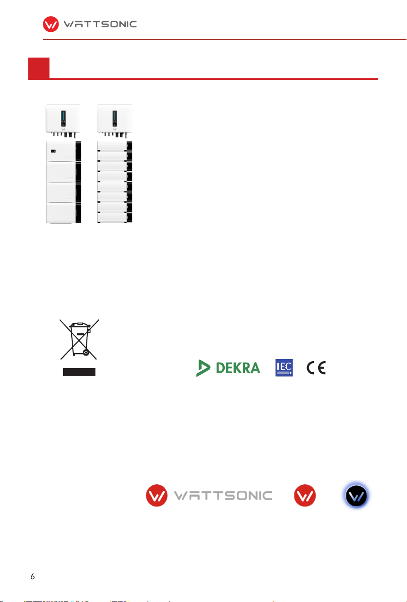
※ 1.3 What is Wattsonic All-in-One ESS

11
※
①
②
③
Indicates a hazard with a high level of risk that, if not avoided, will result
in death or serious inju.
DANGER
Indicates a hazard with a medium level of risk that, if not avoided, could
result in death or serious inju.
WARNING
※ 1.4 How to Use This Manual
※ 1.5 Target Groups
※ 1.6 Symbols

12
Indicates a hazard with a low level of risk that, if not avoided, could
result in minor or moderate inju.
CAUTION
Indicates a situation that, if not avoided, could result in equipment or
propey damage, data loss, equipment peormance degradation.
NOTICE
Indicates additional information, emphasized contents or tips that may
be helpful, e.g., to help you solve problems or save time.
NOTE

13
Safety Instructions
2
①
②
③
④
⑤
⑥
⑦
⑧
⑨
①
②
③
④
⑤
⑥
※ 2.1 Safety Notes
※ 2.2 Statement

14
⑦
⑧
⑨
⑩

15
※
Product Description
3
The system is not suitable for supplying life-sustaining medical devices.
It cannot guarantee backup power in all circumstances.
NOTICE
PV
MODULES
BATTERY
HYBRID
INVERTER
BUCK-UP
LOAD
CURRENT
TRANSFORMER
002456
UTILITYMETER
FORBILLING
PURPOSES
UTILITY
GRID
SMART
METER
ON-GRID
LOAD
TN-S
4.0~20.0KW-3P
Tranformer
TN-C
4.0~20.0KW-3P
Tranformer
TN-C-S
4.0~20.0KW-3P
Tranformer
TT
4.0~20.0KW-3P
Tranformer
SMART
METER
※ 3.1 System Introduction

16
The
3P.
Item Terminal NOTE
1Display and LED panel Display the operation information and working status of
the inveer.
2Hanger Used to hang the inveer on the wall-mounting bracket.
3 DC switch Used to safely disconnect the DC circuit.
4DC input terminal PV connector
5Batte input terminal Batte connector
6COM1 po WiFi/LAN/4G module connector
7COM2 po Multi-function Connector (Meter/BMS/RS485/DRED)
8 On-grid output terminal Used for On-grid output cable connection
9Back-up output terminal Used for Back-up output cable connection
3.2 Product Introduction
1
2
34 5 6 7
8
9

17
Item Indicator Status Description
1Power and
Alarm Indicator
O No power.
Blue
Quick ashing Inveer entered self-test status.
Slow ashing Inveer entered waiting status.
Breathe ashing Inveer works normal.
Orange Breathe ashing Low batte warning, the batte power is
about to reach the SOC protection value.
Red Always on An alarm or fault is detected, view the fault
info on the display.
2Grid
Indicator
O Grid lost.
Slow ashing Inveer detected grid but not running in on-grid mode.
Always on Inveer works in on-grid mode.
3Communica-
tion Indicator
Green Always on The inveer communication is running nor-
mally.
Green Flashing The inveer communicates with EMS or
Master inveer through RS485 or CAN.
Orange Always on The inveer isn’t communicating with
Wattsonic sma meter.
Red Always on The inveer isn’t communicating with the
BMS.
4Display Display o to save power, press the button to wake up the display.
5 Button Switch display information and set parameters by sho press or long press.
1
32
4
5

18
Symbol Description
To avoid the potential eects on the environment and human health as a result
of the presence of hazardous substances in electrical and electronic equipment,
end-users of electrical and electronic equipment should understand the meaning
of the crossed-out wheeled bin symbol. Do not dispose of WEEE as unsoed mu-
nicipal waste and have to collect such WEEE separately.
Please read the instructions carefully before installation.
Do not touch any internal pas of the inveer being disconnected from the mains,
batte and PV input for 10 minutes.
CE mark, the inveer complies with the requirements of the applicable CE guide-
lines.
Danger. Risk of electric shock!
The suace is hot during operation and do not touch.
Additional grounding point.
※ 3.3 Symbols on the Inveer

19
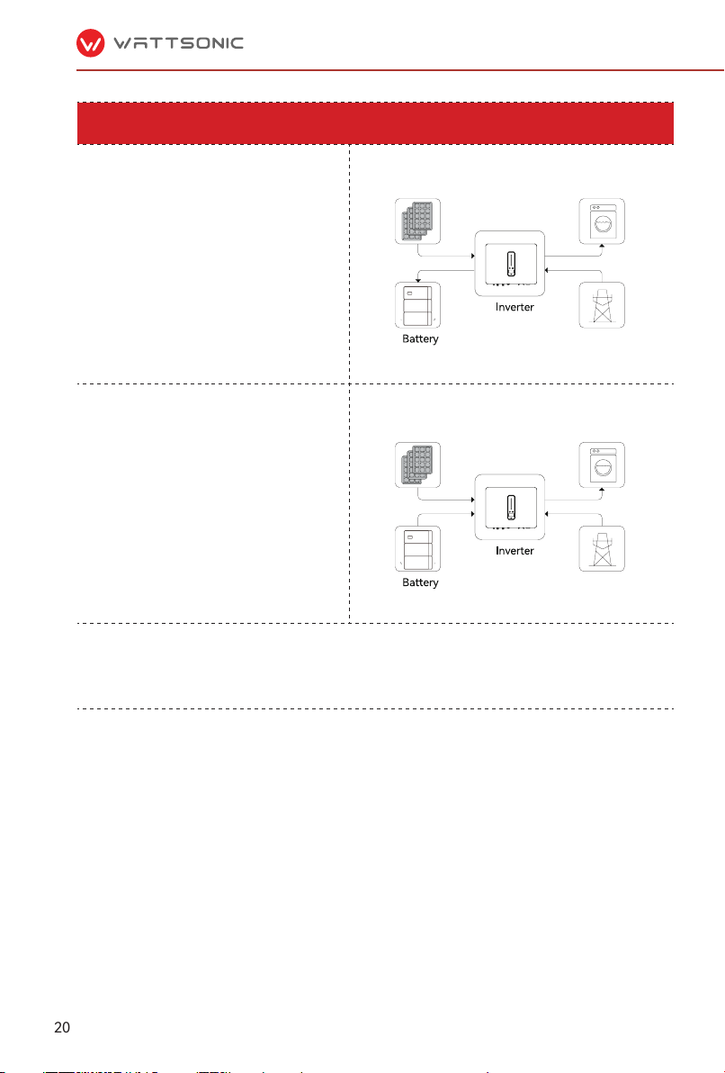
General Mode
In this working mode, when the power from the
PV array is sucient, PV power will supply the
loads, battery, and grid in the order ofloads
rst, batte second, and grid last.
(You can set the power to the grid to 0W when
the local grid doesn’t allow inverter power to
feed to the grid).
When the PV power is insufficient, the battery
will discharge to supply loads, and the grid will
join in if the battery is not enough to supply
loads.
PV Lo
PV Lo
※ 3.4 Operation Modes
20
Peak load Shifting (Load Shifting)
Set the maximum power Pmax (kVA) contracted
with the grid.
When the load consumption is less than the
Pmax, the PV will charge the battery first, and
the grid supplies the load. When the batte is
full, PV will supply the load together with the
grid, but the batte doesn't.
When the load consumption exceeds the Pmax,
the inveer will take power from the batte and
PV to supply power to the load to compensate
for the power that exceeds the Pmax.
*To realize the “Peak load Shifting” function, the load power that exceeded Pmax has to be within the inveer
max output power, otherwise, the inveer will only output the max power which allowed.
PV Lo
PV Lo
>
This manual suits for next models
9
Table of contents
Other wattsonic Inverter manuals


Popular Inverter manuals by other brands


Belle
Belle PWX Series Operator's manual

Power Electronics
Power Electronics SD 500 Series user manual

Votronic
Votronic MobilPOWER SMI 300 Sinus-NVS Installation and operating manual

Darfon
Darfon MIG240 Installation & troubleshooting guide

SMA Solar Technology
SMA Solar Technology SUNNY BOY 1300TL Service manual

SunSynk
SunSynk Hybrid Parity Inverter user manual