East EAHI-6000-SL User manual

Table of Contents
Chapter 1 Introduction ...............................................................................1
1.1 Applicable product.................................................................................................1
1.2 Applicable personnel............................................................................................. 1
1.3 Definition of symbols............................................................................................. 1
1.4 Revision history .................................................................................................... 1
Chapter 2 Safety Precautions....................................................................2
2.1 General safety ...................................................................................................... 2
2.2 Safety of photovoltaic module............................................................................... 2
2.3 Safety of inverter................................................................................................... 3
2.4 Battery safety........................................................................................................ 4
2.5 Personnel requirements........................................................................................ 5
2.6 EU compliance statement..................................................................................... 5
Chapter 3 Product Description..................................................................6
3.1 Product description............................................................................................... 6
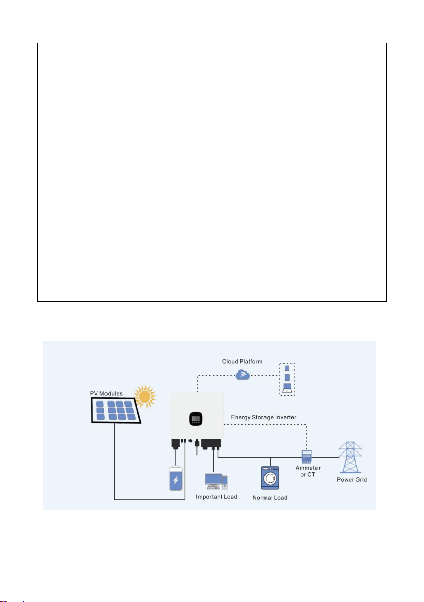
3.2 Application scenarios ............................................................................................ 6
3.3 Operating modes .................................................................................................. 8
3.4 Operation status of inverter................................................................................. 10
3.5 External dimensions.............................................................................................11
Chapter 4 Inverter Storage and Inspection............................................14
4.1 Arrival inspection................................................................................................. 14
4.2 Packing list.......................................................................................................... 14
Chapter 5 Installation ...............................................................................16
5.1 Preparation before installation ............................................................................ 16
5.2 Inverter installation.............................................................................................. 18
Chapter 6 Electrical Connection .............................................................20
6.1 Connection of battery end................................................................................... 22
6.2 PV end connection.............................................................................................. 24
6.3 AC end connection.............................................................................................. 26
6.4 Communication end connection.......................................................................... 29

6.5 Circuit Diagram................................................................................................... 39
Chapter 7 Operation .................................................................................43
7.1 Control panel ...................................................................................................... 43
7.2 Key description................................................................................................... 43
7.3 Failure indication and reminder........................................................................... 44
7.4 Structure of LCD menu....................................................................................... 45
7.5 Menu query......................................................................................................... 46
7.6 System warning .................................................................................................. 46
7.7 History record ..................................................................................................... 47
7.8 Power ON/OFF................................................................................................... 47
7.9 System setting.................................................................................................... 49
7.10 Firmware upgrade............................................................................................. 54
7.11 Parameter configuration.................................................................................... 55
7.12 Product information........................................................................................... 56
Chapter 8 System Maintenance...............................................................57
8.1 Daily maintenance of inverter.............................................................................. 57
8.2 Maintenance of inverter unused for long term..................................................... 57
8.3 Powering off inverter........................................................................................... 57
8.4 Battery maintenance........................................................................................... 58
8.5 Battery safety...................................................................................................... 58
Chapter 9 Troubleshooting......................................................................59
9.1 History record ..................................................................................................... 59
9.2 Clean history....................................................................................................... 59
9.3 Fault list.............................................................................................................. 59
Chapter 10 Technical Data.......................................................................65
Chapter 11 Appendixes ............................................................................68

~ 1 ~
Chapter 1 Introduction
This document mainly describes the product information, installation and wiring, configuration,
debugging, troubleshooting and maintenance methods of the inverter. Before installing and
using the product, please read this document carefully to understand the safety information,
functions and characteristics of the product. This document is subject to update from time to
time. Please visit our official website or contact relevant personnel for the latest version and
more product information.
1.1 Applicable product
This document is applicable to the following models:
EAHI-3000-SL
EAHI-3600-SL
EAHI-5000-SL
EAHI-6000-SL
1.2 Applicable personnel
This document is only applicable to the professionals who know local regulations and standards
and electrical systems well, and have specialized knowledge related to this product after being
trained professionally.
1.3 Definition of symbols
DANGER
“DANGER” indicates a high potential danger which may cause death or sever injury if not
avoided.
WARNING
“WARNING” indicates a moderate potential danger which may cause death or sever injury if
not avoided.
CAUTION
“CAUTION” indicates a low potential danger which may cause mild or moderate injury if not
avoided.
NOTE
“NOTE” indicates emphasis on and supplement to the contents, or the optimized use skill or
know-how of the product, which will help you to solve a problem or save time.
1.4 Revision history
V1.0, first release

~ 2 ~
Chapter 2 Safety Precautions
Make sure to always follow the safety precautions specified herein during operation of the
inverter.
NOTE
The inverter has been designed and tested in strict accordance with safety regulations.
However, for any electrical equipment, the relevant safety instructions should be followed
before any operation on the inverter as any improper operation may lead to serious injury or
property damage.
2.1 General safety
NOTE
•This document is subject to update from time to time due to product version upgrading or
other reasons. Unless otherwise specified, the contents of this document cannot replace the
safety instructions provided in the product label or user manual.All descriptions provided
herein are intended as use guidance only.
•Read this document carefully to understand the products and precautions before installing
the inverter.
•All operations of the inverter must be conducted by professional and qualified technicians
who are familiar with the relevant local standards and safety regulations at the place where
the invert is installed.
•When the inverter is operated, it is necessary to use insulating tools and wear personal
protective equipment to ensure personal safety. Wear anti-static gloves, anti-static bracelet
and anti-static clothing, etc. when touching electronic devices, to protect the inverter against
static.
•Any equipment damage or personnel injury caused by failure to install, use or configure the
inverter as required by this document is not the equipment manufacturer’s responsibility.
Contact the supplier for this document.
2.2 Safety of photovoltaic module
DANGER
Please connect the DC cable of the inverter by using DC wiring terminal supplied with the
product.
Using other DC wiring terminals may lead to serious consequences, and the equipment
damage caused therefore is not the equipment manufacturer’s responsibility.

~ 3 ~
WARNING
•Make sure to properly earth the component frame and the support system.
•After the DC cable is connected, make sure that the cable is tightly connected without
looseness.
•Measure the positive and negative poles of DC cable by a multimeter to ensure that the
positive and negative poles are connected correctly and without reverse connection, and
the voltage is within the allowable range.
•Do not connect the same PV string to multiple inverters in series; otherwise the inverter
may be damaged.
•The photovoltaic module used with the inverter must comply with ClassA standard of
IEC61730.
2.3 Safety of inverter
WARNING
•Make sure that the voltage and frequency of the grid connection point meet the grid
connection specifications of the inverter.
•It is recommended to provide the protection device such as circuit breaker or fuse onAC
side of the inverter, and the specification of the protection device should be greater than
1.25 times the rated AC output current of the inverter.
•The protective earth conductor of the inverter must be connected firmly. When multiple
inverters are used, make sure that equipotential connection is made for all protection ground
points on the inverter housing.
•If the photovoltaic system is not equipped with a battery, it is not recommended to use the
BACK-UP function. The power consumption risk of the system caused thereon is excluded
in the warranty of the equipment manufacturer.
DANGER
•After installation of the inverter, labels and warning signs on the box must be clearly visible,
and shall not be covered, changed and damaged.
•The signs on the inverter box are as follows:

~ 4 ~
There is high temperature on the
surface of the inverter, and it is
forbidden to touch the inverter
when it is running, otherwise it is
possible to cause burns
Delayed discharge. After the
inverter is powered down, please
wait for 5 minutes till the inverter
is fully discharged
Please read the user manual
carefully before operating the
inverter
Potential danger may be caused
during the operation of the
inverter, and protection
measures should be taken
The inverter should not be
treated as domestic waste,
please dispose the inverter
according to local laws and
regulations, or send it back to the
equipment manufacturer
Connection point of protective
earth conductor
CE Marking
RCM Marking
2.4 Battery safety
CAUTION
•The battery used with the inverter shall be approved by the inverter manufacturer, and the list of
approved batteries is available from the official website.
•Before installing the inverter, please carefully read the user manual of the battery to understand
the product and precautions, and strictly follow the operation requirements provided in the user
manual of the battery.
•If the battery has been completely discharged, charge the battery in strict accordance with the
user manual of the battery.
•The battery current may be affected by some factors, such as temperature, humidity and
weather conditions, etc., which may cause battery current limit and affect carrying capacity.
•If the battery does not work, please contact the after-sales service center as soon as possible.
Otherwise, the battery may be permanently damaged.
•Measure the positive and negative poles of DC cable by a multimeter to ensure that the positive
and negative poles are connected correctly, and the voltage is within the allowable range.
•Do not connect a single battery pack to more than one inverter; otherwise the inverter may be
damaged.

~ 5 ~
2.5 Personnel requirements
NOTE
•Installers and maintainers must receive strict training to understand the safety
instructions, and correct operation method.
•The inverters or their components are only installed, operated, maintained and replaced
by the qualified professional or trained professional.
2.6 EU compliance statement
The inverters with wireless communication functions salable in European market meet the
following directives:
•Radio Equipment Directive 2014/53/EU (RED)
•Restrictions of Hazardous Substances Directive 2011/65/EU and (EU) 2015/863 (RoHS)
•Waste Electrical and Electronic Equipment 2012/19/EU
•Registration, Evaluation, Authorization and Restriction of Chemicals (EC) No 1907/2006
(REACH)
The inverters without wireless communication functions salable in European market meet the
following directives:
•Electromagnetic compatibility Directive 2014/30/EU (EMC)
•Electrical Apparatus Low Voltage Directive 2014/35/EU (LVD)
•Restrictions of Hazardous Substances Directive 2011/65/EU and (EU) 2015/863 (RoHS)
•Waste Electrical and Electronic Equipment 2012/19/EU
•Registration, Evaluation,Authorization and Restriction of Chemicals (EC) No 1907/2006
Please contact the suppliers for more EU compliance statements (REACH).

~ 6 ~
Chapter 3 Product Description
3.1 Product description
EAHI-3000~6000-SLinverter is used to control and optimize the energy flow in the photovoltaic
system through an integrated energy management system. With the inverter, the power energy
generated in the photovoltaic system can be supplied for the load, stored in the battery, and
outputted to the grid. The inverter integrates with power supply, battery and Internet for
connection with grid, photovoltaic panels and the Internet of things to supply the power for
families, small supermarkets, farms and other places.
Product features:
Graphic LCD and key design, user-friendly interface
One-key remote control and OTA upgrade function accessible to digital power station
maintenance
24-hour intelligent energy management to understand the status of photovoltaic power
station in real time
Charging and discharging time and power settable flexibly for peak load shifting
Uninterruptible power supply, switchable within 20ms
Continuous off-grid power supply capacity up to 6KW
High charging and discharging efficiency to improve the economic benefits of system
Intelligent BMS function to improve battery reliability
Compatible with lead-acid and lithium batteries, which can match economic solutions of
different markets
High frequency isolation technology used to provide higher system safety and long service
life
3.2 Application scenarios
WARNING
•The photovoltaic system is not suitable for connection with the devices requiring stable
power supply, such as life-sustaining medical devices. Make sure that no personal injury is
caused in case of system failure.
•If the photovoltaic system is not equipped with a battery, it is not recommended to use the

~ 7 ~
BACK-UP function. The power consumption risk of the system caused therefore is excluded
from the warranty of the equipment manufacturer.
•The battery current may be affected by some factors, such as temperature, humidity,
weather conditions, etc., which may cause battery current limit and affect carrying capacity.
•If overload protection is triggered on the inverter for single time, the inverter can be restarted
automatically; if overload protection is repeated, the restarting time of the inverter will be
prolonged. If it is required to restart the inverter as soon as possible, the inverter may be
restarted immediately by App.
•If, during grid failure, load capacity is more than the rated power of the inverter, the off-grid
function of the inverter will be disenabled automatically; when the inverter is restarted, close
large load to ensure that the load power is less than the rated power of the inverter.
•The inverter has overload capacity and EPS function at the BACK-UP output port (switching
time <20ms), and may supply the power for normal use in ordinary domestic load in case of
grid failure. To ensure EPS switchover and power supply stability of the load, do not use the
loads requiring high starting current as much as possible, such as high-power water pumps.
The supported load sizes are as follows:
Total power of inductive load and capacitive load ≤ 1 x rated output power of inverter
General application scenario

~ 8 ~
3.3 Operating modes
Name
Operation logic
Counter-current
protection mode
After connection with the grid, PV does not supply the power to the grid
in all operating modes;
Grid-
Tied
mode
Battery-
first mode
(1) PV gives priority to supply the power for the backup load, followed
by charging the battery, and supplies excess energy to the domestic
loads and the grid;
(2) If the power from the PV is less than the power of the backup load,
the battery supplies the power for the backup load and the PV does
not supply the power to the grid.
(3) The battery is not charged by the grid.
Domestic
load-first
mode
(1) PV gives priority to supply the power for the backup load and the
domestic load, followed by charging the battery, and supplies
excess energy to the domestic loads and the grid;
(2) If the power from the PV is less than the power of the backup load
and the domestic load, the battery supplies the power for the
backup load and the domestic load, and the PV does notsupply the
power to the grid.
(3) The battery is not charged by the grid.
Grid-first
mode
(1) PV gives priority to supply the power for the backup load, followed
by supplying the power for the domestic load and the grid , and
charge the batter by excess energy ;
(2) If the power from the PV is less than the power of the backup load,
the battery supplies the power for the backup load and the PV does
not supply the power to the grid.
(3) The battery is not charged by the grid.
Full power
feed mode
(1) PV gives priority to supply the power for the backup load, followed
by supplying the power for the domestic load and the grid, and
charge the batter by excess energy ;
(2) If the power from the PV is less than the maximum output power of
the inverter, the battery supplies the power to make up the
difference, so that the inverter outputs maximum power.
(3) The battery is not charged by the grid.

~ 9 ~
Grid-
Tied
mode
Emergency
backup
mode
(1)PV gives priority to charge the battery, followed by supplying the
power for the backup load and supplies excess energy to the
domestic loads and the grid;
(2)If the power from the PV is not enough to the backup load,the grid
supplies the power required for the backup load and the domestic
load.
(3)If the power from the PV is unavailable or extremely low, the grid
charges the battery and supplies the power for the backup load
and the domestic load;
AC
charging-
post
backup
mode
(1)PV gives priority to charge the battery, followed by supplying the
power for the load and supplies excess energy to the grid;
(2)If the power from the PV is not enough to the load, thegrid supplies
the power required for the backup load and the domestic load.
(3)If the power from the PV is unavailable or extremely low, the grid
supplies the power for the backup load and the domestic load, but
does not charge the battery;
PV mode
The battery can be charged but not discharged
(1)PV energy gives priority to the backup load and household load
power supply, followed by battery charging, excess energy to the
grid;
(2)The PV energy is less than the backup load plus the household
load, and the power grid supplements the backup load and the
insufficient part of the household load;
(3)The grid does not charge the battery.
Forced off-
grid mode
During the normal operation of the gird, force to operate in the off-grid
mode
Off--grid mode (no
grid)
(1)PV gives priority tosupply the power for the backup load, followed
by charging the battery.
(2)If the power from the PV is unavailable or extremely low, PV and
the battery supply the power for the load.

~ 10 ~
3.4 Operation status of inverter
No.
Status
Description
1
Waiting mode
Waiting period after the inverter is turned
• If the condition is met, the inverter enters the self-check mode.
•In case of a fault, the inverter enters the fault mode.
2
Self-check
mode
Continuous self-check, initialization and so on before the inverter
is started
• If the condition is met, the inverter enters and starts to operate
in the grid-tied mode.
• If the grid is not detected, the inverter enters and stars to
operate in the off-grid mode; if it has no off-grid function, the
inverter enters the waiting mode.
• In case of failure in the self-check, the inverter enters the fault
mode.
3
Grid-tied
mode
Grid-tied operation of inverter
• If the grid is not detected, the inverter enters the off-grid mode.
• If a fault is detected, the inverter enters the fault mode.
• If the grid fails to meet the grid-tied requirements and the off-
grid output function is not activated, the inverter enters the
waiting mode.
4
Off-grid mode
In case of grid fault, the inverter enters the off-grid mode, and
continuously supplies the power for the load by BACK-UP port.

~ 11 ~
4
Off-grid mode
• If a fault is detected, the inverter enters the fault mode.
• If the grid fails to meet the grid-tied requirements and the off-
grid output function is not activated, the inverter enters the
waiting mode.
• If the gridmeets the grid-tiedrequirement andthe off-grid output
function is activated, the inverter enters the self-check mode.
5
Fault mode
If a fault is detected, the inverter enters the fault mode. After the
fault is removed, it enters the waiting mode.
3.5 External dimensions
3.5.1 Appearance description

~ 12 ~
No
Identification
Purpose
1
Battery terminal
Connect the battery
2
Positive PV terminal
Connect the PV positive electrode
3
Negative PV terminal
Connect the PV negative electrode
4
PV input switch
Connect/ disconnect the PV switch
5
Vent valve
Discharge the growing air from housing
6
GPRS/WIFI
The inverter uploads the data/ connects with the upper
computer by GPRS/WIFI
7
USB
USB upgrade interface
8
Dry contact input
Connect the user’s dry contact circuit
9
Safety communication
Reserved according toAustralia safety regulation
10
CT or kilo-watt-hour
meter signal input
CT or kilo-watt-hour meter signal input provided
externally on the inverter
11
RS485
RS485 communication with the upper computer
12
NTC temperature
sampling
Reserved
13
BMS communication
Battery communication input
14
AC wiring terminal
Load and grid input
3.5.2 Nameplate description
A user may identify the inverter by the nameplate provided on the side of the inverter. The
nameplate indicates inverter information, such as model, important parameters, certification
marks and place of production, etc., and must not be damaged or covered.

~ 13 ~
Fig. 3.5.2 Nameplate information (subject to change without further notice and actual nameplate)

~ 14 ~
Chapter 4 Inverter Storage and Inspection
WARNING
If the inverter is not immediately used, please store the inverter as following:
1. Make sure that the external packing is not opened.
2. Make sure that the storage environment is clean and at suitable temperature (-25-60℃,
non-condensing)
3. Make sure that the inverter is placed according tothe stacking height and direction provided
in the label attached on the packing.
4. Make sure that the inverter will not topple over during storage.
5. If the inverter is stored for long period, the inverter should be checked by the professional
before use.
4.1 Arrival inspection
Upon reception, please inspect the following carefully.
1. Check the external packing for damage, deformation, hole, crack, and other signs showing
inverter damage. If yes, do not open the packing, and contact the distributor.
2. Check the inverter model. If incorrect, do not open the packing, and contact the distributor.
3. Check the type, quantity and appearance of the inverter and its components and
accessories. If damaged, contact the distributor.
4.2 Packing list
No
Name
Specification
Quantity
Picture
1
Inverter
Inverter
1
2
Expansion pipes
and bolts
M6*50mm, installed on wall
3
3
Combination
screw
Used to install the waterproof cover
10
4
PV+ connector
VP-D4B-CHSM4 terminal male
housing
Including metal terminal
2
5
PV- connector
VP-D4B-CHSF4 terminal male
housing
Including metal terminal
2

~ 15 ~
6
Intelligent kilo-
watt-hour meter
DDS3366D/DDS3366D-J
(delivered with delivery)
(optional, alternative with CT)
1
7
Communication
cable
Single naked cope with RJ45
registered jack on one end, and
two pins (pin 4,pin 5), the rest is
cut, and 40mm external insulation
and 5mm cable insulation
removed on another end, 3m
long, used to connect inverter
with the kilo-watt-hour meter
1
8
Earth conductor
screws
Cross outer hexagon double pad
screws M6*12mm
1
9
Earth conductor
end soldering
lug
RNB5.5-
6,48A,Φ=6.5mm,5.6×23mm
1
10
EPS
Grid wiring
terminal
Tube type pre-insulated end
E6012(10AWG-6mm2) red
6
11
Copper battery
wiring terminal
Copper tube terminal,SC25-6
2
12
User manual
Grid-connected and off-grid
inverter specifications
1
13
WiFi data
collector
LSW-5A7153,5-12Vdc
1
14
Mounting plate
Housing accessory used to
installed wall-mounted inverter
1
15
Mounting plate
bolt
Cross outer hexagon double pad
screws, M6×20
2
16
Waterproof
cover for
battery
Housing accessory
1
17
Waterproof
cover for
communication
and AC
Housing accessory
1

~ 16 ~
Chapter 5 Installation
5.1 Preparation before installation
Installation environment requirements
The ambient temperature should be between -25℃and +60℃, and the relative humidity
should be between 0% and 90% (no condensation).
The inverter can be installed indoors or outdoors dry and well ventilated environment
without excessive dust, but not in direct sunlight or near heating equipment.
The inverter may generate noise (25dB or less) during operation. Please install the
inverter far away from the rest area.
The inverter should be installed on firm bearing surface, and installation location and
method must fit with the weight and dimension of the inverter.
The inverter should be installed vertically or at not more than 15°backward tilt, and must
not be installed at frontward tilt, or diagonally and horizontally.
During installation of the inverter, the display panel should be aligned with line of sight to
facilitate the operation.
The wiring terminals should be protected by the waterproof cover and tightened.
The inverter should be installed at less than 4000m altitude.
The inverter should be installed away from high-intensity magnetic field to avoid
electromagnetic interference. If there is a radio station or less than 30MHz wireless
telecom equipment nearby the installation site, the inverter should be installed as
following:
①Add a ferrite core with multi-turn winding or low pass EMI filter for the DC input cable
or AC output cable of the inverter.
②The inverter should be more than 30m from the wireless electromagnetic interference
equipment.

~ 17 ~
Requirements for installation tools
Type
Tools and Descriptions
installation
safety

~ 18 ~
5.2 Inverter installation
5.2.1 Inverter handling
NOTE
• Transport, handling, installation and other operations of the inverter should meet the national
and local laws and regulations and relevant standards of the installation location.
• Before installation, move the inverter to the installation location, avoid personnel injury or
inverter damage and pay attention to the following during handling:
1. Allocate the personnel according to the weight of the inverter to avoid the injury caused by
more inverter weight than the carrying capacity of the personnel.
2. Please wear safety gloves to avoid injury.
3. Ensure that the inverter is balanced to avoid falling during handling.
5.2.2 Inverter installation
NOTE
• During drilling, drill the hole away from the pipe and cables installed in the wall to avoid
danger.
• During drilling, wear safety goggles and a dust mask to prevent the dust from entering the
respiratory tract or the eyes.
• Make sure to firmly install the inverter to avoid personnel injury caused by falling.
Installation procedure:
①Identify the hole location on the wall according to the hole on the mounting plate.
②Drill the mounting hole at the identified location by an electric drill according to the
specified of the expansion bolt, fix the mounting plate on the wall by the expansion bolts, and
tighten the nut by at least 30Nm torque. Recommend M6×50 expansion bolts.
This manual suits for next models
3
Table of contents
Other East Inverter manuals