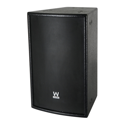
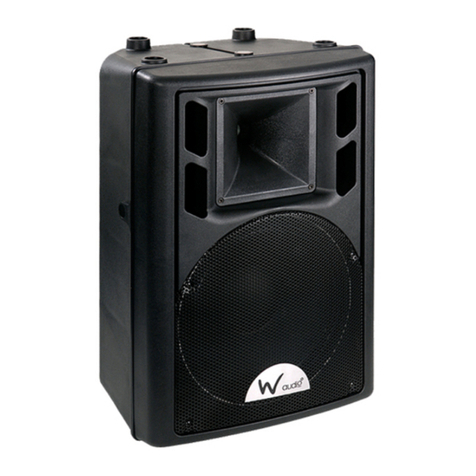
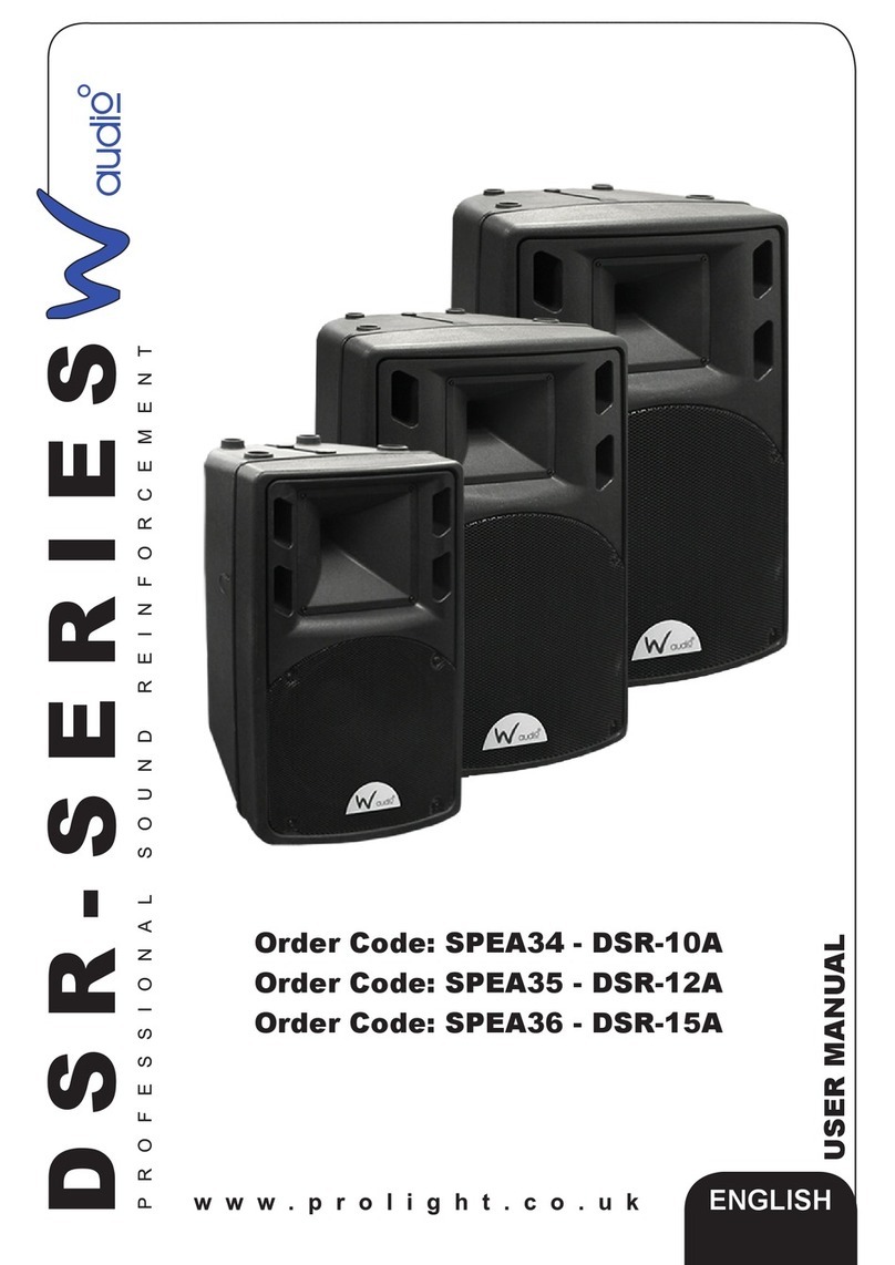
Waudio DSR 15A User manual

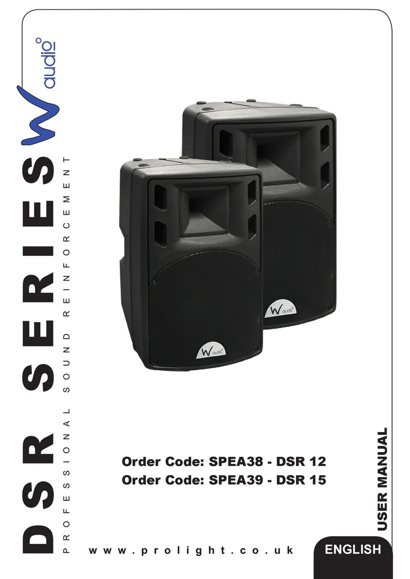
Order codes:
SPEA34 - DSR 10A
SPEA35 - DSR 12A
SPEA36 - DSR 15A
DSR Series
Active Speakers
User Manual

www.prolight.co.uk DSR Series Active Speakers User Manual
2
Safety advice
WARNING
FOR YOUR OWN SAFETY, PLEASE READ THIS USER MANUAL
CAREFULLY BEFORE YOUR INITIAL START-UP!
• Immediatelyuponreceivingthisproduct,carefullyunpackthecartonandcheckthecontents
toensurethatallthepartsarepresent.
• Beforeinitialstart-up,pleasemakesurethatthereisnodamagecausedduringtransportation.
• Shouldtherebeanydamage,consultyourdealeranddonotusetheequipment.
• Retainthecartonandallpackagingmaterials.
• Intheeventthattheequipmentmustbereturnedtothesupplier,itisimportantthat
theequipmentisreturnedintheoriginalcartonandpackaging.
• Tomaintaintheequipmentingoodworkingconditionandtoensuresafeoperation,
itisnecessaryfortheusertofollowthesafetyinstructionsandwarningnoteswritteninthismanual.
• Pleasenotethatdamagescausedbyusermodicationstothisequipmentarenotsubjecttowarranty.
IMPORTANT:
The manufacturer will not accept liability for any resulting damages caused by the non-observance
of this manual or any unauthorised modication to the equipment.
OPERATING DETERMINATIONS
Ifthisequipmentisoperatedinanyotherway,thanthosedescribedinthismanual,theproductmaysufferdamageand
thewarrantybecomesvoid.Incorrectoperationmayleadtodangere.g:short-circuit,burnsandelectricshocksetc.
Incaseofmalfunctionthisunitshouldbereturnedforserviceorinspection.
Donotendangeryourownsafetyandthesafetyofothers!
Incorrectinstallationorusecancauseseriousdamagetopeopleand/orproperty.
• Neverletthepowercablecomeintocontactwithother
cables.Handlethepowercableandallmainsvoltage
connectionswithcaution!
• Neverremovewarningorinformativelabelsfromthe
equipment.
• Donotopenormodifytheequipment.
• Donotconnectthisequipmenttoadimmer-pack.
• Donotswitchtheequipmentonandoffinshortintervals,
asthiswillreducethesystem’slife.
• Onlyusetheequipmentindoors.
• Donotexposetoammablesources,liquidsorgases.
• Alwaysdisconnectthepowerfromthemainswhen
equipmentisnotinuseorbeforecleaning!Onlyhandle
thepowercablebytheplug.Neverpullouttheplugby
pullingthepowercable.
• Makesurethattheavailablevoltage
isbetween220V/240V.
• Makesurethatthepowercableisnevercrimped
ordamaged.Checktheequipmentandthepower
cableperiodically.
• Iftheequipmentisdroppedordamaged,disconnect
themainspowersupplyimmediately.Haveaqualied
engineerinspecttheequipmentbeforeoperatingagain.
• Iftheequipmenthasbeenexposedtodrastictemperature
uctuation(e.g.aftertransportation),donotswitchiton
immediately.Thearisingcondensationmightdamagethe
equipment.Leavetheequipmentswitchedoffuntilithas
reachedroomtemperature.
• Iftheproductfailstofunctioncorrectly,discontinueuse
immediately.Packsecurely(preferablyintheoriginal
packingmaterial),andreturntoyourdealerforservice.
• Onlyusefusesofsametypeandrating.
• Repairs,servicingandpowerconnectionmustonlybe
carriedoutbyaqualiedtechnician.THISUNITCONTAINS
NOUSERSERVICEABLEPARTS.
• WARRANTY:Oneyearfromdateofpurchase.
CAUTION!
KEEP THIS EQUIPMENT
AWAY FROM MOISTURE,
RAIN AND LIQUIDS, AND
OUT OF DAMP/HUMID
ENVIRONMENTS
DANGER TO LIFE!
BEFORE OPERATING THE
SPEAKER FOR THE FIRST
TIME, THE INSTALLATION
HAS TO BE APPROVED
BY AN EXPERT
CAUTION!
TAKE CARE USING
THIS EQUIPMENT!
HIGH VOLTAGE-RISK
OF ELECTRIC SHOCK!!

www.prolight.co.uk DSR Series Active Speakers User Manual
3
Safe installation
Makesurethattheareabelowtheinstallationplaceisblockedwhenrigging,deriggingorservicing
thesystem.Please note: WAudiocannotbemadeliablefordamagescausedbyincorrectinstallations
andexcessivenoiselevels.
Unpacking and transportation:
Unpacktheunitsandexaminethemfortransportdamage.
Whenboxedintheoriginalpackagingthespeakersystemshouldbecarriedbytwopersonsofthe
samesize.Carryingthespeakersystemwithonepersonaloneshouldbeavoidedastheheavyweight
andstraincouldleadtobackinjury.Pleasenotethatallspeakersystemsweighingmorethan25kg
mustbetransportedbytwopersons.
Pleasenotethatspeakersystemscanmoveduetobassbeatsandvibrations.
Furthermore,unintendedpushingonthespeakerspresentafurtherrisk.Thespeakersystem
mustalwaysbesecuredagainstmovingortherespectiveareahastobeblocked.
Safety advice
DANGER TO LIFE!
A FALLING SPEAKER SYSTEM CAN
CAUSE DEADLY ACCIDENTS, ALL SAFETY
INSTRUCTIONS GIVEN IN THIS MANUAL
MUST BE OBSERVED.
CAUTION - FIRE HAZARD!
KEEP AWAY FROM CIGARETTES,
FIRE AND HEATERS ETC. TREAT THE
SURFACE WITH A FIRE RETARDANT
AT REGULAR INTERVALS.
DANGER!
IMPACT HAZARD
SECONDARY ATTACHMENT
REQUIRED FOR OVERHEAD
INSTALLATION!
DANGER TO LIFE DUE
TO FALLING SPEAKER
SYSTEMS.
WARNING!
LOUD NOISE HAZARD
EAR PROTECTION
MUST BE WORN

www.prolight.co.uk DSR Series Active Speakers User Manual
4
Product overview
TheDSRseriesofferssuperiorsoundandhasfeaturesthatuntilnowhave
onlybeenfoundonmoreexpensiveequipment.Safeandeasyinstallation
ispossiblebymultipleriggingpointsandfunctionalcasingdesigngivestrue
multifunctioncapabilitywithoutcompromise.TheDSRRangefeatureVariFlare;
arotatabletopendhornare.ThisfeatureallowsaninstallertotailortheHF
dispersiontotheapplicationmakingtheDSRrangeidealasafoldbackmonitor
orhorizontalinstallationcabinet.
•Highimpactmolded
polypropyleneenclosure
•Heavydutydynamicswitchmode
powersupply
•Built-inhighlyefcientclassD
(LF)+AB(HF)ampliers
•10",12",15"low-mid
frequencytransducers
•1"compressionhighfrequencydriver
•80°x60°coveragepattern
•Smoothresponsewithhighpower
•5integralsuspensionpoints
•Integral35mmtophat
foroptionalpolemounting
•Optionalpaddedtransit
coversavailable
DSR Series Active Speakers
Specications DSR 10A DSR 12A DSR 15A
Frequencyrange(-10dB) 60Hz~19kHz 56Hz~19kHz 45Hz~19kHz
Frequencyresponse(-3dB) 70Hz~19kHz 65Hz~19kHz 55Hz~19kHz
Highpassfrequency 40Hz 40Hz 40Hz
MaximumcalculatedSPL 123dB 125dB 127dB
Horizontalcoverage 80° 80° 80°
Verticalcoverage 60° 60° 60°
Max.systempower 700W 900W 1000W
AmplierpowerLF 300Wrms 400Wrms 450Wrms
AmplierpowerHF 50Wrms 50Wrms 50Wrms
LFtransducer 10"/50mm 12"/50mm 15"/65mm
HFtransducer 1"/25mm 1"/25mm 1"/25mm
Crossoverfrequency 2.5kHz 2.2kHz 2.2kHz
Loop/mixout XLR/Mbalanced XLR/Mbalanced XLR/Mbalanced
ACinput 220-240V~50/60Hz 220-240V~50/60Hz 220-240V~50/60Hz
Fuserating T4A250V T4A250V T4A250V
Dimensions(HxWxD) 557x332x313mm 615x416x356mm 740x475x400mm
Weight 14.5kg 17kg 22.5kg
Ordercode SPEA34 SPEA35 SPEA36
Inthebox:
1 x active speaker,
1 x IEC power cable
& 1 x user manual
416mm 356mm
615mm
475mm 400mm
740mm
332mm 313mm
557mm
DSR15A dimensionsDSR12A dimensionsDSR10A dimensions

www.prolight.co.uk DSR Series Active Speakers User Manual
5
DSR SERIES
WARNING: TO REDUCE THE RISK OF FIRE OR ELECTRIC SHOCK.
DO NOT EXPOSE THIS EQUIPMENT TO RAIN OR MOISTURE
CAUTION: TO PREVENT ELECTRIC SHOCK DO NOT REMOVE
TOP OR BOTTOM COVERS. NO USER SERVICABLE PARTS INSIDE
CAUTION
RISK OF ELECTRIC SHOCK
DO NOT OPEN
POWER ON
HF
LF
LIMIT
MICROPHONE
MIC INPUT
LINE
LINE INPUT MIX OUTPUT
BASS
0
-10 +10
TREBLE
0
-10 +10
MIC VOL
0
-10 +10
LINE VOL
0
-10 +10
MASTER VOL
0
-10 +10
MAINS INPUT
AC 230V 50/60Hz
FUSE
T4A/250V
I
I
POWER
I
O
ONLY USE WITH A 250V FUSE
Technical specications
02
01
03
04
08
13
06
11
15
12
05
09
16
07
10
14

www.prolight.co.uk DSR Series Active Speakers User Manual
6
Operating instructions
Satellite speaker:
1 HF Limit LED:TheHFLimitLEDilluminatesyellowwhentheHFamplierisbeginningtoclip.TheLEDindicates
totheusertheamplierslimithasbeenreached,theoverallsystemgainortheHFgainshouldbereduced
untiltheLEDceasestoilluminate.Failuretoobservetheinstructionmayresultincomponentfailurewithinthe
loudspeakerenclosure.
2 LF Limit LED:TheLFLimitLEDilluminatesredwhentheLFamplierisbeginningtoclip.TheLEDindicatesto
theusertheamplierslimithasbeenreached,theoverallsystemgainortheLFgainshouldbereduceduntil
theLEDceasestoilluminate.Failuretoobservetheinstructionmayresultincomponentfailurewithinthe
loudspeakerenclosure.
3 Active LED:ThisLEDilluminateswhentheunitisswitchedonandreadyforuse.ShouldtheLEDfaililluminate
pleasecarefullycheckthemainsvoltagesupplyandmainsinletfuse,ifthemainsupplyandfusehavebeen
veriedandtheunitdoesnotshowactivepleaseconsultyou’reWAudiodealerforadviceandservice.
4 Bass (LF) Control:ThebassresponsefortheDSR-Aloudspeakercanbeadjustedby+-10dB.Duringnormal
operationthebasscontrolshouldbesettothecentre(0)positionandthenadjustedinsmallamountstosuit
theroomacousticsormusicalcontent.
5 Treble (HF) Control:ThetrebleresponsefortheDSR-Aloudspeakercanbeadjustedby+-10dB.Duringnormal
operationthetreblecontrolshouldbesettothecentre(0)positionandthenadjustedinsmallamountstosuit
theroomacousticsormusicalcontent.
6 Line Input Gain Control: InputgaincontrolforthebalancedXLRlinelevelsignalinput.Beforeconnectingsignal
cablesthegaincontrolshouldbeturnedfullyclockwise.Turnclockwisetoincreaseinputgain.
7 Master Volume Control: Volume(level)controlfortheDSR-Aloudspeaker.Beforeconnectingsignalcablesthe
Volumecontrolshouldbeturnedfullyclockwise.Turnclockwisetoincreaseloudspeakeroutputlevel.
8 Microphone (MIC) Input: BalancedXLRmicrophonelevelinputsuitableforusewithdynamicmicrophonesor
condensermicrophoneswiththeuseofanexternal+48Vphantompowersupply.
9 Microphone (MIC) Input Gain Control: InputgaincontrolforthebalancedXLRmicrophonelevelsignalinput.
Beforeconnectingsignalcablesthegaincontrolshouldbeturnedfullyclockwise.Turnclockwisetoincrease
inputgain.
10 Line Input: BalancedXLRlinelevelinputsuitableforinputforconnectiontolinelevelsources
suchasmixingconsoles.
11 MIX output:BalancedXLRlineleveloutput,theMIXoutputisacombinedsignalcontainingboththe
XLRlineinputandalsotheXLRmicrophoneinput.Thisoutputcanbeusedtolinksignaltoadditional
DSR-Aloudspeakers.
12 Heat Sink:Theheatsinkassemblydissipatesheatgeneratedbytheinternalampliermodules,toensure
reliableoperationtheheatsinkassemblyshouldbekeptclearofdust,dirtoranyobstructions.Ifusingthe
DSR-Aloudspeakerinsideapaddedbagcareshouldbetakentoensurethefreeowofairaroundtheheat
sinkassemblybyopeningtherearap.
13 Mains Input: ConnecttheDSR-ALoudspeakertothemainsoutletusingthesupplied13ABS1363IECpower
cord.Careshouldbetakentoensurethemainsoutletvoltageis220-240Vac50~60Hz.
14 Earth Connection: TheDSR-AloudspeakerisaClass1productdesignedtobeearthedatalltimes.
Donotremoveortamperwiththeprotectiveearthconnection.
15 Mains Power Switch: Mainspoweron/offforthesystem.Connectionsforsignalinput/outputshouldbemade
beforetheloudspeakerispoweredon.
16 Mains Fuse: TheDSR-AloudspeakerfeaturesafusedIECmainsinlet.

www.prolight.co.uk DSR Series Active Speakers User Manual
7
Start Up
Placethespeakertothedesiredinstallationareaandcarefullyturnitontoitsfeet.
Makesurethatthepowerswitchissetto“OFF”beforeyouconnectanyaudiocables.
Inputs
Thisspeakersystemistobedirectlyconnectedtotheoutputsofyouraudiomixerorkeyboardetc.
Agoodqualitycablerunimprovesthesoundqualityconsiderably.Inputcablesshouldbeshortand
direct,sincehighfrequenciesmaybeabsorbedifthecablesareunnecessarilylong.Alsoalonger
cablemayleadtohummingandnoiseproblems.Iflongcablesrunsareunavoidable,youshould
usebalancedcables.
Connection
• Beforeconnectingthespeakersandaudiosourcetothisdevice,makesurethatallvolume/gain
controlsareturnedfullyanti-clockwiseintheminimumposition.
• TurnonthemainspowerswitchandthemainsLEDwillilluminate.
• IMPORTANT! DO NOT OVERDRIVE THE SYSTEM. Ifanydistortionorclippingisaudibleyoumustreduce
theinputsignallevelorreducethevolumeofthesatellitespeakersandbass.Failuretodosowill
causedamagetotheamplierandorspeakers.
Operating instructions & example setups

www.prolight.co.uk DSR Series Active Speakers User Manual
8
Mono two speaker
Stereo two speaker
Example setups
DSR SERIES
WARNING:TO REDUCE THE RISK O F FIRE OR ELECTRIC SHOCK.
DONOT EXP OSE THIS EQUIPMENT TO RAIN OR MOISTURE
CAUTION: TO PREVENT ELECTRIC SHOCK DO NOT REMOVE
TOPOR BOT TOM COVERS. NO USER SERVICABLE PARTS INSIDE
CAUTION
RISKOF ELECTRIC SHOCK
DONOT OPEN
POWER ON
HF
LF
LIMIT
MICROPHONE
MIC INPUT
LINE
LINE INPUT MIX OUTPUT
BASS
0
-10 +10
TREBLE
0
-10 +10
MIC VOL
0
-10 +10
LINE VOL
0
-10 +10
MASTER VOL
0
-10 +10
MAINS INPUT
AC 230V 50/60Hz
FUSE
T4A/250V
I
I
POWER
I
O
ONLYUSE WITH A 250V FUSE
MONO SUM

www.prolight.co.uk DSR Series Active Speakers User Manual
9
Four speaker stereo system
Common standalone mono speaker system
iPod or other
line level source
Microphone
source
DSR SERIES
WARNING:TO REDUCE THE RISK OF FI RE OR ELECTRIC SHOCK.
DONOT EXP OSE THIS EQUIPMENT TO RAIN OR MOISTURE
CAUTION: TO PREVENT ELECTRIC SHOCK DO NOT REMOVE
TOPOR BOT TOM COVERS. NO USER SERVICABLE PARTS INSIDE
CAUTION
RISKOF ELECTRIC SHOCK
DONOT OPEN
POWER ON
HF
LF
LIMIT
MICROPHONE
MIC INPUT
LINE
LINE INPUT MIX OUTPUT
BASS
0
-10 +10
TREBLE
0
-10 +10
MIC VOL
0
-10 +10
LINE VOL
0
-10 +10
MASTER VOL
0
-10 +10
MAINS INPUT
AC 230V 50/60Hz
FUSE
T4A/250V
I
I
POWER
I
O
ONLYUSE WITH A 250V FUSE
DSR SERIES
WARNING:TO REDUCE THE RISK O F FIRE OR ELECTRIC SHOCK.
DONOT EXP OSE THIS EQUIPMENT TO RAIN OR MOISTURE
CAUTION: TO PREVENT ELECTRIC SHOCK DO NOT REMOVE
TOPOR BOT TOM COVERS. NO USER SERVICABLE PARTS INSIDE
CAUTION
RISKOF ELECTRIC SHOCK
DONOT OPEN
POWER ON
HF
LF
LIMIT
MICROPHONE
MIC INPUT
LINE
LINE INPUT MIX OUTPUT
BASS
0
-10 +10
TREBLE
0
-10 +10
MIC VOL
0
-10 +10
LINE VOL
0
-10 +10
MASTER VOL
0
-10 +10
MAINS INPUT
AC 230V 50/60Hz
FUSE
T4A/250V
I
I
POWER
I
O
ONLYUSE WITH A 250V FUSE
Example setups

www.prolight.co.uk DSR Series Active Speakers User Manual
10
Stereo system with one LSR 115P powered subwoofer
Example setups
DSR SERIES
WARNING:TO REDUCE THE RISK OF FI RE OR ELECTRIC SHOCK.
DONOT EXP OSE THIS EQUIPMENT TO RAIN OR MOISTURE
CAUTION: TO PREVENT ELECTRIC SHOCK DO NOT REMOVE
TOPOR BOT TOM COVERS. NO USER SERVICABLE PARTS INSIDE
CAUTION
RISKOF ELECTRIC SHOCK
DONOT OPEN
POWER ON
HF
LF
LIMIT
MICROPHONE
MIC INPUT
LINE
LINE INPUT MIX OUTPUT
BASS
0
-10 +10
TREBLE
0
-10 +10
MIC VOL
0
-10 +10
LINE VOL
0
-10 +10
MASTER VOL
0
-10 +10
MAINS INPUT
AC 230V 50/60Hz
FUSE
T4A/250V
I
I
POWER
I
O
ONLYUSE WITH A 250V FUSE
DSR SERIES
WARNING:TO REDUCE THE RISK OF FI RE OR ELECTRIC SHOCK.
DONOT EXP OSE THIS EQUIPMENT TO RAIN OR MOISTURE
CAUTION: TO PREVENT ELECTRIC SHOCK DO NOT REMOVE
TOPOR BOT TOM COVERS. NO USER SERVICABLE PARTS INSIDE
CAUTION
RISKOF ELECTRIC SHOCK
DONOT OPEN
POWER ON
HF
LF
LIMIT
MICROPHONE
MIC INPUT
LINE
LINE INPUT MIX OUTPUT
BASS
0
-10 +10
TREBLE
0
-10 +10
MIC VOL
0
-10 +10
LINE VOL
0
-10 +10
MASTER VOL
0
-10 +10
MAINS INPUT
AC 230V 50/60Hz
FUSE
T4A/250V
I
I
POWER
I
O
ONLYUSE WITH A 250V FUSE
DSR 10A
DSR 12A
DSR 15A
Audio Mixer
LSR 115P
Powered Subwoofer
DSR 10A
DSR 12A
DSR 15A
• 80Hz or 125Hz
high pass lter
activated
• Subwoofer in
parallel mode

www.prolight.co.uk DSR Series Active Speakers User Manual
11
Stereo system with two LSR 115P powered subwoofers & two active mid/high cabinets
Example setups
DSR SERIES
WARNING:TO REDUCE THE RISK OF FI RE OR ELECTRIC SHOCK.
DONOT EXP OSE THIS EQUIPMENT TO RAIN OR MOISTURE
CAUTION: TO PREVENT ELECTRIC SHOCK DO NOT REMOVE
TOPOR BOT TOM COVERS. NO USER SERVICABLE PARTS INSIDE
CAUTION
RISKOF ELECTRIC SHOCK
DONOT OPEN
POWER ON
HF
LF
LIMIT
MICROPHONE
MIC INPUT
LINE
LINE INPUT MIX OUTPUT
BASS
0
-10 +10
TREBLE
0
-10 +10
MIC VOL
0
-10 +10
LINE VOL
0
-10 +10
MASTER VOL
0
-10 +10
MAINS INPUT
AC 230V 50/60Hz
FUSE
T4A/250V
I
I
POWER
I
O
ONLYUSE WITH A 250V FUSE
DSR SERIES
WARNING:TO REDUCE THE RISK OF FI RE OR ELECTRIC SHOCK.
DONOT EXP OSE THIS EQUIPMENT TO RAIN OR MOISTURE
CAUTION: TO PREVENT ELECTRIC SHOCK DO NOT REMOVE
TOPOR BOT TOM COVERS. NO USER SERVICABLE PARTS INSIDE
CAUTION
RISKOF ELECTRIC SHOCK
DONOT OPEN
POWER ON
HF
LF
LIMIT
MICROPHONE
MIC INPUT
LINE
LINE INPUT MIX OUTPUT
BASS
0
-10 +10
TREBLE
0
-10 +10
MIC VOL
0
-10 +10
LINE VOL
0
-10 +10
MASTER VOL
0
-10 +10
MAINS INPUT
AC 230V 50/60Hz
FUSE
T4A/250V
I
I
POWER
I
O
ONLYUSE WITH A 250V FUSE
DSR 12A
DSR 15A
Audio Mixer
• 80Hz or 125Hz
high pass lter
activated
• Subwoofer in
parallel mode
LSR 115P
Powered Subwoofer
DSR 12A
DSR 15A

www.prolight.co.uk DSR Series Active Speakers User Manual
12
Balanced XLR Connection
Connection With The Mains
ConnecttheunittothemainsviatheIECmains
inletusingthe13AUK-IECcordsupplied.
The earth has to be connected.
Switchtheuniton.Afterswitchingonthespeaker
system,wait8-10secondsbeforeyouturnthevolume
controlupinordertoavoidspeakerdamage.
CAUTION!IncreasethelevelofeachchanneluptothepointwheretheclipLEDsilluminate.
Alwayscheckthesoundpressurelevelwithameterinordertokeeptothelegalthreshold.
Jack plug
Replacing The Fuse
CAUTION!Beforereplacingthefuse,pleasemakesurethatmainscableisunplugged.
Procedure
Step1:Unscrewthefuseholderandtherearpanelwithascrewdriver(anti-clockwise).
Step2:Removetheoldfusefromthefuseholder.
Step3:Installanewfuseofthesametypeandrating.
Step4:Replacethefuseholderinthehousingandxit.
Operating instructions

www.prolight.co.uk DSR Series Active Speakers User Manual
13
Installation on a Speaker Stand
Thespeakersystemmayonlybeinstalledonaspeakerstandifthe
originalspeakersystemisequippedwithanappropriatestandadaptor.
Standsorsatellitesystemsmustonlybeinstalledonaplaneareawith
amaximuminclinationangleof5°.
CAUTION:Speakersystemsinstalledundertheinuenceofhorizontal
forces,e.g.wind,canbeimpaired.Thisiswhyadditionalsafetymeasures
likeattachingballastweightshavetobetaken.
Ifinclinedtensioncablesorprolongedoutriggersareused,theareaof
dangerhastomarkedorblocked.
Beforeliftingorloweringthetelescopictubes,youmustalwaysblock
asafetyareaaroundthestandorsatellitesystem.Thissafetyarea
musthaveadiameterof1.5timesthemaximumheight.
Liftedtelescopictubesalwayshavetobesecuredwithasecondary
securingattachment.
Thetotalweightoftheinstallation(totalweightofsystemincludingindividual
parts)mustneverexceedthemaximumloadoftheinstallationarea.
Unintendedmovementoftheloadhastobeavoided-alsoincaseofre!
Loosenthexingscrewsofthelegs,pullthelegsoutuntilthecrossstruts
areata90˚angletothelegs.Tightenthexingscrewsofthelegs.
Installation Of The Speaker System
CAUTION:Theloadshavetobeinstalledinabalancedway.
CAUTION:Thecarryingcapacityofthestandorspeakerstand
mustneverbeexceeded.(Note: Stand/s not included)
Wall Installation
Thespeakersystemcanonlybeinstalledonawall,iftheoriginal
speakersystemisequippedwithanappropriatemountingpoint.
Beforeattachingthespeakersystem,makesurethattheinstallation
areacanholdaminimumpointloadof10timestheinstallationsweight.
(E.g.13kg-130kgpointload).
Thedurabilityoftheinstallationdependsverymuchonthematerial
usedattheinstallationarea(buildingmaterial),suchaswood,
concreteandbricketc.Thisiswhythexingmaterialmustbechosen
tosuitthewallmaterial.Alwaysaskaspecialistforthecorrect
plug/screwcombinationindicatingthemaximumloadand
buildingmaterial.(Note: Wall bracket/s not included)
Installation instructions

www.prolight.co.uk DSR Series Active Speakers User Manual
14
Overhead Installation
Ifthespeakersystemistobeinstalledwithamountingheightofmorethan1m
(e.g.onastageorframework),thespeakersystemmustalwaysbesecuredwithan
appropriatesecondarysecuringattachment.
Theinstallationmustalwaysbesecuredwithasecondarysafetyattachment.e.g.anappropriate
catchnet.Thesecondarysafetyattachmentmustbeconstructedinawaythatnopartofthe
installationcanfalldownifthemainattachmentfails.
Whenrigging,derigging,orservicingthespeakersystemstandingintheareabelow
theinstallationplace,onbridgesorotherendangeredareasareforbidden.
Theoperatorhastomakesurethatthesafetydataisapprovedbyanexpertbeforeoperation
forthersttimeandafteranychangesaremade.
Theoperatorhastomakesurethatthesafetydataisapprovedbyanexpertaftereveryfouryears
inthecourseofanacceptancetest.
Theoperatorhastomakesurethatthesafetyinstallationdataisapprovedbyaskilledperson
onceayear.
Procedure
Thespeakersystemshouldbeinstalledoutsideareaswherepersonsmaywalkbyorseated.
IMPORTANT! OVER HEAD RIGGING REQUIRES EXTENSIVE EXPERIENCEincluding(butnotlimitedto)
calculatingworkinglimits,installationmaterialsused,andperiodicsafetyinspectionofallinstallation
materialsandthespeakersystem.Ifyoulackthesequalications,donotattempttheinstallation
yourself,butinsteaduseaprofessionalstructuralrigger.Improperinstallationcanresultinbodily
injuryanddamagetoyourproperty.
Thespeakersystemhastobeinstalledoutofthereachofpeople.
CAUTION:Speakersystemsinoverheadinstallationsmaycausesevereinjurieswhenfalling!
Ifyouhavedoubtsconcerningthesafetyofapossibleinstallation,donotinstallthespeakersystem!
Beforeriggingmakesurethattheinstallationareacanholdaminimumpointloadof10timesthe
speakersystemsweight.
Installation instructions

www.prolight.co.uk DSR Series Active Speakers User Manual
15
Flying the speakers
Thespeakermustalwaysbesecuredwiththreeappropriateeyeboltsandthreeappropriate
safetyropes.Theeyeletsandthesafetyropesmustalwaysholdatleast12timestheweight
ofthespeakersystem.(Note: Wall bracket/s not included)
Please note:Beforeinstallingtheeyebolts,makesurethatthethreadisisalwaysinperfectcondition
andfreefromdirt.Installtheeyeboltsinthethreadedholesonthespeakersystem.Theeyeboltsmust
betighteneduntilthestopposition,handtightwithoutanytools.Insertthequicklinksofthesafety
ropesintheeyeboltsofthespeakersystem.Pullthesafetyropesoverasafexingspot.Inserttheend
intothequicklinkandtightenthesafetyscrew.
Themaximumdropdistancemustneverexceed20cm.
Asafetyropewhichhasalreadyheldthestrainofafallandisdefectivemustnotbeusedagain.
DANGER TO LIFE - DUE TO FALLING SPEAKERS SYSTEMS!
THE SPEAKER MUST ONLY BE SUSPENDED BY EXPERIENCED AND TRAINED
PERSONS, AND SHOULD BE APPROVED BY AN EXPERT

www.prolight.co.uk DSR Series Active Speakers User Manual
16
WEEE notice
Correct Disposal of this Product
(Waste Electrical & Electronic Equipment)
(Applicable in the European Union and other European countries
with separate collection systems)
Thismarkingshownontheproductoritsliterature,indicatesthatitshouldnotbedisposed
withotherhouseholdwastesattheendofitsworkinglife.Topreventpossibleharmtothe
environmentorhumanhealthfromuncontrolledwastedisposal,pleaseseparatethisfromother
typesofwastesandrecycleitresponsiblytopromotethesustainablereuseofmaterialresources.
Householdusersshouldcontacteithertheretailerwheretheypurchasedthisproduct,ortheir
localgovernmentofce,fordetailsofwhereandhowtheycantakethisitemforenvironmentally
saferecycling.
Businessusersshouldcontacttheirsupplierandcheckthetermsandconditionsofthe
purchasecontract.Thisproductshouldnotbemixedwithothercommercialwastesfordisposal.
Table of contents
Other Waudio Speakers manuals

Waudio
Waudio PSR-12A User manual

Waudio
Waudio PSR-8i User manual

Waudio
Waudio PSR-8 User manual

Waudio
Waudio Epic T12 User manual

Waudio
Waudio DSR 10A User manual

Waudio
Waudio PSR-15A User manual

Waudio
Waudio PSR-10A NEO User manual

Waudio
Waudio Epic Sub112 User manual

Waudio
Waudio RX Series User manual

Waudio
Waudio Epic Sub 110 User manual