INERT AIR (N2) SYSTEM MANUAL
Inert Air (N2) Systems are manufactured and distributed by Waukesha®Service & Components, a division of SPX Transformer Solutions, Inc.
N2-Manual, REV 2.16, 11/2/2019 3
GENERAL INFORMATION
Positive pressure nitrogen gas pressurizing systems protect transformer oil in the main tank from exposure
to both oxidation and moisture, thereby maintaining the highest quality insulating oil.
DESCRIPTION
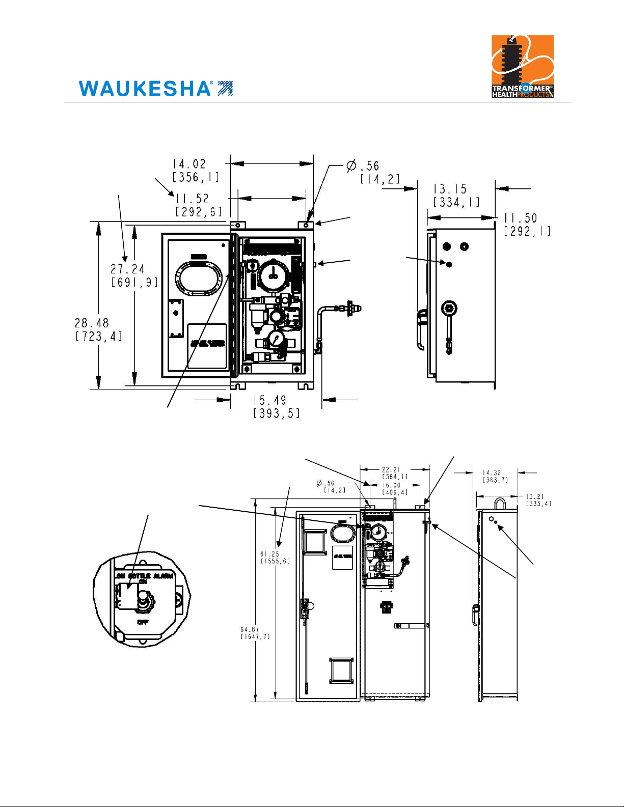
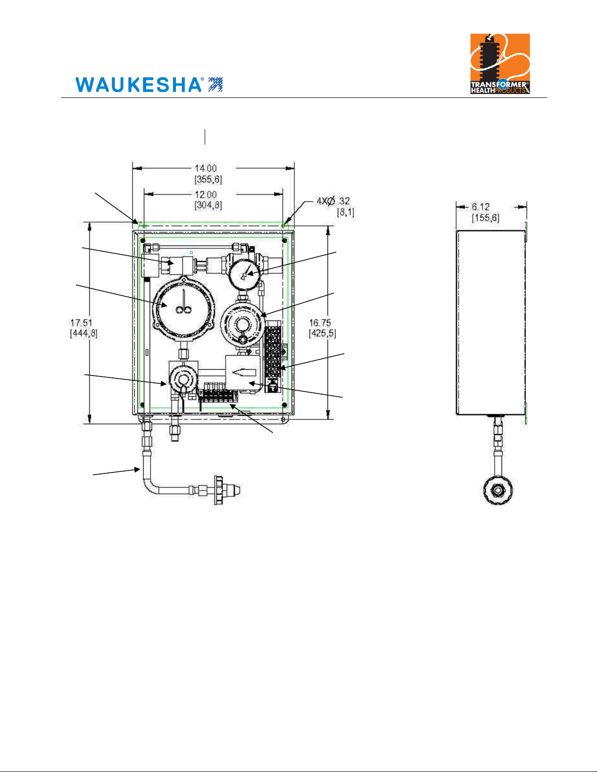
The nitrogen regulation system (see Figure 1, page 5) consists of a nitrogen gas supply cylinder with its
own control valve, a supply pressure gauge, a three-stage pressure reducing assembly and the piping and
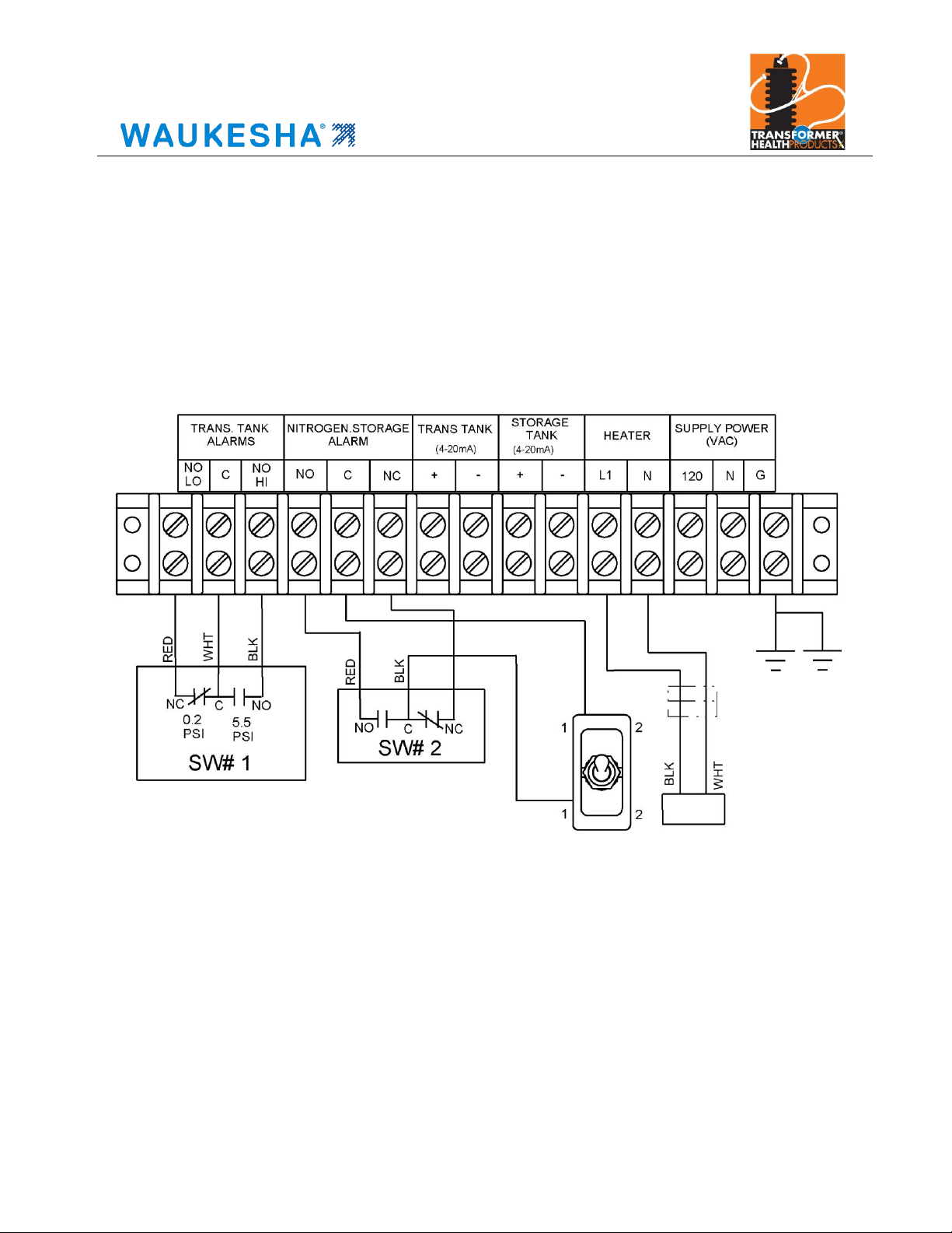
valves that control the flow of gas to and from the tank. The system includes electrical connection points for
low gas supply, high tank pressure and low tank pressure alarms. Provisions for pressure transmitters for
bottle supply and tank pressures are included as well.
When the nitrogen regulation system is correctly set-up and operating, transformer tank pressure will
maintain at 0.5 psi minimum and 5.0 psi maximum. During periods of transformer cooling, the overall tank
pressure will decrease. If the tank pressure drops below 0.5 psi, nitrogen gas flows from the bottle supply
cylinder through the reducing valve assembly and into the tank until the 0.5 psi pressure is restored. During
periods of transformer heating, tank pressure will increase. If tank pressure exceeds 5.0 psi, the regulator
assembly will vent the excess nitrogen to atmosphere to prevent tank damage or PRD operation.
The 3rd stage regulator supplying nitrogen to the transformer tank has an adjustable range of 0–2 psi and is
set to a slight positive pressure (0.5 psi standard) at the factory. A 0.5 psi nitrogen supply pressure and a
relief valve breaking pressure of 5.0 psi are chosen in order to provide a 4.5 psi tank regulation band.
Increasing the nitrogen supply pressure will decrease the regulation band for the transformer tank and may
increase nitrogen use during periods of heavy thermal cycling.
Adjustable alarm contacts are provided to indicate max/min tank pressures selected by user. Typical alarm
points would be set just outside of the selected regulation band. For example, user alarms are normally
recommended to be set for 0.2 psi and 5.5 psi for a 0.5 to 5.0 regulation band. Nitrogen regulation systems
are available in several configurations, as shown in Figures 2, 3 and 4 on pages 6 and 7.
INSTALLATION
The N2 system is easy to install and maintain. The following should be noted during installation:
Mount the cabinet so that the bottom is at least 4” above grade.
Use 3/8” diameter mounting hardware to mount the cabinet securely to the side of the transformer.
Use sealed fittings for the electrical connections to avoid water accumulation inside the enclosure.
Electrical connection points are provided on either side of the box and are sized for standard 1/2”
conduit fittings.
Ensure piping to the transformer is clean and free from corrosion or rust. The N2 system is equipped
with 1/4” NPT female connections for both the transformer tank inlet (left side of cabinet) and outlet
(right side of cabinet) points. Valves located inside the cabinet walls allow the user to control the inlet
and outlet flow for the tank piping.