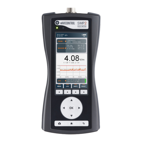
WAVECONTROL SMP2 User manual

Electromagnetic Field Meter
SMP2
V1.21
Safety, Quality, Service
+34 93 320 80 55
www.wavecontrol.com
info@wavecontrol.com
USER’S MANUAL

P. 2www.wavecontrol.com
User’s Manual
Electromagnetic Field Meter
Index
1. WARNINGS AND PRECAUTIONS..........................................................5
2. INTRODUCTION.......................................................................................6
3. FIRST STEPS ............................................................................................7
4. GETTING STARTED.................................................................................8
4.1 Overview.........................................................................................8
4.2 Field probes..................................................................................10
4.2.1 Connector type ...................................................................10
4.2.2 Screw connector................................................................11
4.2.3 Push-pull connector..........................................................11
4.3 External connections..................................................................12
4.3.1 USB .......................................................................................12
4.3.2 Fibre optic............................................................................12
5. SMP2 – INITIAL USE ............................................................................13
5.1 Switching the apparatus on and off.........................................13
5.2 Main screen..................................................................................13
5.3 Menu screen.................................................................................16
5.4 Measurement Options screen ..................................................16
5.5 Measurement Log screen..........................................................18
5.6 GPS screen ...................................................................................18
5.7 Settings screen............................................................................19
6. FUNCTIONS ........................................................................................... 20
6.1 Measurement modes................................................................. 20
6.1.1 Temporal mode - time domain measurements........... 20
6.1.2 FFT mode - frequency domain measurements.......... 21
6.1.3 Log Frequency Log mode................................................ 23
6.1.4 Spatial average................................................................... 24
6.2 Time domain weighting ............................................................ 24
6.3 Alarm ............................................................................................ 25
6.4 GPS ............................................................................................... 25

P. 3www.wavecontrol.com
User’s Manual
Electromagnetic Field Meter
7. BAT TERY INFORMATION .................................................................... 26
7.1 General information.................................................................... 26
7.2 Recharging................................................................................... 26
8. SOFTWARE............................................................................................ 27
8.1 Installing the software ............................................................... 27
8.2 System requirements ................................................................ 28
8.3 Using the PC software .............................................................. 28
8.3.1 Measurements screen ..................................................... 28
8.3.2 Screenshots screen.......................................................... 29
8.3.3 Information screen ........................................................... 29
8.3.4 Spreadsheet exporting..................................................... 29
8.3.5 Control centre screen....................................................... 30
8.4 Live screen................................................................................... 31
9. FIRMWARE UPDATING ........................................................................ 32
10. MAINTENANCE................................................................................... 33
10.1 Cleaning the apparatus and the screen ............................... 33
10.2 Handling the equipment ......................................................... 33
10.3 Periodic recalibrations ............................................................ 33
11. TECHNICAL SPECIFICATIONS ......................................................... 34
12. WARRANTY ......................................................................................... 35
ANNEX 1. WP400 PROBE SPECIAL FUNCTIONS............................... 36
ANNEX 2. WPF18 PROBE SPECIAL FUNCTIONS............................... 38
ANNEX 3. COMMUNICATION PROTOCOL........................................... 39
DECLARATION OF CONFORMITY (DOC) ............................................. 45

P. 4www.wavecontrol.com
User’s Manual
Electromagnetic Field Meter
Congratulations for your acquisition
of a Wavecontrol SMP2.
This Manual provides you with instructions
for using and handling your SMP2.
Please read this Manual carefully before using
your SMP2.

P. 5www.wavecontrol.com
User’s Manual
Electromagnetic Field Meter
Environmental information
Disposal of your old product:
Your product is designed and manufactured with
high quality materials and components, which
can be recycled and reused.
When this crossed-out wheeled bin symbol is
attached to a product it means the product is
covered by the European Directive 2002/96/EC.
Please get informed about the local separate
collection system for electrical and electronic
products.
Please act according to your local rules and do
not dispose of your old products with your normal
household waste. The correct disposal of your
old product will help prevent potential negative
consequences for the environment and human
health.
1. WARNINGS AND PRECAUTIONS
Review this manual and become familiar with
all the instructions for using and handling your
SMP2.
Your SMP2 is a portable apparatus with
a rechargeable battery. Before taking any
measurement, make sure that the battery is
sufciently charged for the time that you need for
the measurement. If it is not, recharge the battery
before.
Your SMP2 is not watertight and it should be
protected from moisture, such as rain.
Adjustment, maintenance, or repair of the
equipment must be performed only by qualied
personnel. Please get in touch with Wavecontrol
or your sales contact.
Never overtighten when screwing the SMP2
on the tripod since the thread engagement could
break down.

P. 6www.wavecontrol.com
User’s Manual
Electromagnetic Field Meter
Those measurements can be made quickly and
easily anywhere because the SMP2 is portable
and simple to handle and use.
The SMP2 can sample the eld level continuously
and store that data automatically in its built-
in memory at user-congured intervals with a
capacity of up to 1 000 000 samples.
The data stored in the memory can be easily
downloaded to a computer via a USB or ber
optics port for later processing.
The SMP2 is also available with a built-in GPS
receiver (optional) to allow each measurement to
be associated automatically with the geographic
location where it was taken.
The SMP2 Portable Electromagnetic Field
Monitoring System can measure electromagnetic
eld levels generated by any source within the
frequency range of the probe attached to the
system.
It combines 2 instruments in 1: broadband
measurements and selective measurements
(FFT), including % direct EMF exposure
assessments to limit lines by using the weighted
peak exposure (WPE) technique.
The SMP2 has been developed to meet
demanding customer requirements in the RF safety
measurements domain. Its versatility makes it
a perfect measurement tool for many different
sectors and industries such as Railway, Power,
Manufacturing, Chemical, Medical, Defence, RFID
and EAS, Telecommunications, etc.
2. INTRODUCTION

P. 7www.wavecontrol.com
User’s Manual
Electromagnetic Field Meter
Figure 1: Case
Flash drive
SMP2 and USB cable
below
Field Probe
Field Probe
Battery charger
3. FIRST STEPS
• SMP2.
• 1 or more electromagnetic eld probes.
• Battery charger.
• USB key containing the User’s Manual and
SMP2 software.
• USB – mini USB cable.
• Fibre optic link (optional).
If any of those components is missing, please
contact Wavecontrol.
This section contains instructions for unpacking
and checking the equipment when you receive it.
1) When you receive the equipment, check the
packaging to see if it has been damaged in any
way. Make a description of any damage on the
delivery note before you sign it.
2) Check that all the components of the SMP2
are there. The SMP2 is delivered in a compact
briefcase that should contain the following
components:

P. 8www.wavecontrol.com
User’s Manual
Electromagnetic Field Meter
4. GETTING STARTED
4.1 Overview
The front panel of the SMP2 contains the user
interface, made up of the screen and keypad.
Figure 2: Front
The keyboard presents 8 standard buttons, 4
virtual buttons (below the screen) and 1 ON/OFF
button.
• : These arrows allow you to move
through the menu options and the data stored
in memory.
• : allows to validate an option or enter in a
menu.
• : always allows to come back to the main
screen (measuring screen).
• : allows to get back to an earlier menu or to
cancel a selection.
• : allows to take print-screens anywhere in
the program.
The top of the SMP2 holds the eld probe
connector.

P. 9www.wavecontrol.com
User’s Manual
Electromagnetic Field Meter
Light sensor
On/Off button
Probe connector
Status LED
Integrated GPS patch
antenna
Figure 3: Top
• Probe connector: (see 4.2).
• On / Off button: switches the equipment on
and off.
• Status LED: when the unit is off, red means
charging, green charged. When the unit is on,
green LED should be always on.
• Light sensor: allows to control the automatic
screen back-light intensity depending on
ambient light.
The bottom of the SMP2 holds the other
connections of the equipment.
Mini USB connector
Charger connector
Tripod ¼’ screw
Fibre optic connector
Figure 4: Bottom

P. 10www.wavecontrol.com
User’s Manual
Electromagnetic Field Meter
• Mini USB connector and bre optics: allows
connection to a PC in order to:
• Download data stored in the SMP2 memory.
• Update rmware for the equipment.
• Control the unit remotely.
• Battery charger connector: allows the SMP2
battery to be recharged using the charger
supplied with the equipment.
• ¼’ screw connector: takes a ¼’ screw, the
standard screw used for most tripods, allowing
the SMP2 to be mounted on a tripod.
4.2 Field probes
The SMP2 is a highly versatile EMF measurement
device that requires connection of the proper
eld probe to obtain the best results for each
application. Only Wavecontrol eld probes will
work with the device.
If the device is switched on with no eld probe
attached, it will not show any eld value and
therefore no measurement will be saved
to memory. However, saved data and GPS
positioning functions will be available.
The SMP2 automatically detects the type of eld
probe and its calibration parameters.
4.2.1 Connector type
There are two types of connector: push-pull and
screw.
Figure 5: Push-pull connector
Figure 6: Screw connector

P. 11www.wavecontrol.com
User’s Manual
Electromagnetic Field Meter
4.2.2 Screw connector
4.2.2.1 How to connect the eld probe
Connect the eld probe by inserting the male
connector into the female connector with the tab
aligned. Once fully inserted, screw the connector
until it is snug, without forcing it.
Tab
Sleeve to screw on after
inserting the probe
Figure 7: How to connect the eld probe
4.2.2.2 How to disconnect the eld probe
First unscrew the probe connector, then pull the
connector to remove it.
Important: pull the connector.
Do not try to twist or turn the probe tube.
4.2.3 Push-pull connector
4.2.3.1 How to connect the push-pull probe
With a push-pull connector, the eld probe is
connected by inserting the male connector into
the female connector of the SMP2 until it stops.
The polarity of the connector must be observed
and so the red marks on the male and female.
connectors must line up.
Figure 8: How to connect the eld probe
4.2.3.2 How to disconnect the eld probe
You do not need to switch the device off before you
disconnect the eld probe. Pull the connector of the
probe rmly with one hand (pulling with the thumb)
while you hold the SMP2 with your other hand as
shown in the pictures below:
Figure 9: How to disconnect the eld probe

P. 12www.wavecontrol.com
User’s Manual
Electromagnetic Field Meter
Note: no need to install additional software, everything
has been already installed with the main software.
Note2: in case the connector does not t into a small
waveguide, you can break the connector in 2 parts.
Important: pull the connector. Don’t pull any
other part of the probe!
Don’t try to twist or unscrew the probe.
4.3 External connections
4.3.1 USB
A USB to mini USB cable is delivered with the
SMP2. After installing the SMP2 software (rst
install the software see 8.1) just plug the cable to
the SMP2 and to the computer. You will be able to
download stored measurements to the computer
or update the SMP2 rmware.
Note: it is not recommended to perform
measurements while the USB is connected, it could
affect the quality of the readings.
4.3.2 Fibre optic
Breakable part see Note2
A bre optic link is available as an option in order
to remotely control and see live readings of the
instrument from a PC without interfering with the
measurements. To connect the bre optic link:
• Plug the bre to the SMP2 (respect the colour
code, grey side is looking up).
• Plug the bre to the USB to bre converter
(respect the colour code).
• Plug the USB of the converter to the PC.

P. 13www.wavecontrol.com
User’s Manual
Electromagnetic Field Meter
Note: All device’s congurations (alarm level, units,
type of measurement, measurement interval, etc.)
are saved when it is switched off and recovered
automatically when it is switched on.
5.2 Main screen
The main screen provides instantaneous and
continuous information on the electromagnetic
eld being measured.
• Date and time: date and time of the apparatus.
• Icons: several icons give some information on
the state of the unit.
Alarm is activated USB is connected
Fibre connection
available
Schedule measure
is activated
• Battery : battery charge level.
Battery discharged
Battery fully charged
• Probe information: serial number of the
eld probe attached to the apparatus and its
frequency information.
5. SMP2 – initial use
The SMP2 is designed for simple and intuitive
operation with 2 basic functions:
• Time or frequency domain eld measurement.
• Storage of results in memory.
Several additional functions make the SMP2 a
very complete eld measurement system.
The SMP2 is controlled via the keypad and easy
access to data is available through the different
screens.
5.1 Switching the apparatus on and off
The apparatus is switched on and off with the
On / Off button located on the upper part of the
keyboard.
To power on the unit, click on the On/Off
button. The status LED will stay in red for some
milliseconds before turning green. A welcome
screen is displayed until the software completely
boots and shows the main screen.
To power off the unit, click once on the On/Off
button. A pop-up will appear on the screen to
conrm the command. F1 and F2 buttons will
conrm the action, F3 and F4 buttons will cancel
it. You can also select the option with the right
and left arrows and click on OK to conrm.

P. 14www.wavecontrol.com
User’s Manual
Electromagnetic Field Meter
Figure 10: Main screen
Measurement information:
• Maximum, minimum and average values: these
values are initialized when beginning a new log
or can also be initialized with the virtual button
“Reset”. Average value is updated depending on
the type of averaging and interval chosen in the
Measurement Options.
• Logging and average parameters:
1. Average window time.
2.Type of interval (sliding or arithmetic).
3.Logging time.
Field information: (updated twice per second)
• Total eld: instantaneous total eld level.
Obtained, for three-axis probes as:
• The quadratic sum of each axis eld (for eld
intensity units):
222 ZYXTot EEEE ++=
• The sum of each axis eld (for power density
units):
ZYXTot SSSS ++=
Battery
Date and time
Probe information
Measurement information
Field information
Graph
GPS information
Functions
Icons

P. 15www.wavecontrol.com
User’s Manual
Electromagnetic Field Meter
Functions:
These menus depend on the probe connected but
general functions are as follows:
• Menu: access to the menu screen.
• Log: start a new measurement.
• Units: change the current units (this will reset
the min, max, average and graph). With the up
and down arrow you can select the unit. By
pressing OK the highlighted unit will be selected.
• Reset: it resets the min, max, average and
graph.
• Keypad Arrows in frequency mode:
• Right-left arrows shift the cursor by one step.
• Up-down arrows shift the cursor to the next
right or left peak found in the FFT:
Note: When there are more than 4 functions available,
the button on the right allows to show more functions
available.
• Field unit: unit of measurement of the eld
value shown on the display. This unit applies
to the total eld, the eld on each axis and the
maximum, minimum and average values.
• Field on each axis: the eld measured on each
axis for isotropic three-axis probes. Updated
twice per second.
Graph:
In the time domain: It shows a graphical view of
the temporal evolution of the eld. It represents
the last measurements. This time scale can be
modied in the settings menu (graph timespan).
In the frequency domain: it shows the frequency
information of the signal (horizontal axies
value depend on the span). Also a vertical line
represents the position of the cursor (with the
associated information on the right top side of
the graph).
GPS information:
Positioning information provided by the GPS
receiver. This information is only displayed when
the GPS is switched on.
• Lat: latitude.
• Lon: longitude.
On the right side a colour indicates the quality of
the position:
• Red: bad.
• Orange: average.
• Green: good.

P. 16www.wavecontrol.com
User’s Manual
Electromagnetic Field Meter
5.4 Measurement Options screen
This screen is used to congure different
parameters related to measurement behaviour.
It appears as a menu with a scrolling bar. The
parameters to be congured are shown on the left
and the different options for each parameter are
shown on the right.
The keypad is used to move along the menu. The
process for changing the value of a parameter is:
• Run through the different parameters using the
arrows .
• To change a parameter, press Enter when the
cursor is on that parameter. A pop-up will
appear showing all the possible values.
• Run through the different values using the
arrows and click on OK to select the
desired value. (you can cancel with the back
button).
• When nished you can either press again back
to return to the menu screen or press the home
button to come back to the main screen.
5.3 Menu screen
This is the main screen to access sub menus.
• Conguration measurement (allows to change
all the parameters related to measurement).
• Measurement log (allows to see the stored
measurements).
• GPS (allows to change GPS parameters).
• Settings (allows to change general parameters
of the unit).
• Messages. (in case some events are available
this menu will appear).

P. 17www.wavecontrol.com
User’s Manual
Electromagnetic Field Meter
• Average type: two types of average are
available: arithmetic (a new average is
calculated every average interval) , sliding (a
new average is calculated every new sample).
• Average interval: used to select the time
interval for calculation of the average. The
available intervals are 10s, 15s, 30s, 1min, 2min,
5min, 6min, 10min, 15min and 30min.
• Sampling mode: choice between a single
temporal log or several spatial measurements
that will be represented in a column graphical
chart.
• PostProcessing: this menu is only available
with broadband probes that have correction
factors in memory. It has 3 parameters:
• Enable correction: allows correction of
the value measured at a given frequency
(Working frequency dened below) using the
factors measured during the latest laboratory
calibration.
• Limit value for results in %: allows direct
reading of the eld as a % of a limit dened
on the main measurement screen. This is a
software calculation taking the limit value in
V/m and comparing it with the reading from
the probe. You can select the lower limit
(minimum value) of the regulation (within
the band width of the probe) or a specied
frequency (Working frequency dened below).
Note: If the minimum value is selected, no working
frequency can be dened and therefore the correction
factors cannot be activated.
• Working frequency: allows denition of the
working frequency for correction factors or
for calculation of the value as %. Where the
lower limit of the regulation is selected, this
parameter will show as “Not available”, since
it is not compatible with that selected mode.
The following parameters can be congured:
• Standard: List of preselected standards.
This will affect other parameters that will
not be editable. For example: if you choose
ICNIRP standard then all the parameters in
“Measurement behaviour” will not be editable
as they are dened by the standard.
• Measurement time: allows to dene a
maximum time for the measurement. Available
values are: not limited, 1min, 5min, 6min, 10min,
15min, 30min, 1h, 2h, or custom from 1sec to
100 hours.
• Log interval: used to select the time interval
for storage of data in memory (see section
6.1.1). A datum will be stored every ‘Log interval’
seconds (or minutes). The available intervals are
0.5s, 1s, 5s, 10s, 15s, 30s, 1min and 6min.

P. 18www.wavecontrol.com
User’s Manual
Electromagnetic Field Meter
From this menu you can use the “SHOW”
virtual button to show a specic measurement
(by pressing OK), “ERASE” to erase a single
measurement, or “ERASE ALL” to erase all the
memorised data (this is the same as “erase
all measurements” on the measurement
conguration screen).
When a measurement is entered, you can view a
measurement summary screen. To view the data,
use the “Show data” virtual button.
On the data screen, each rectangle represents a
measurement point. You can use the up or left
arrows to go to directly to the latest point. Where
a screenshot exists, you can display that image by
pressing OK on the selected point.
5.6 GPS screen
This screen has the same layout and behavior
as the Measurement Options screen. It allows to
modify the GPS parameters. Those parameters
are:
• Format: allows to select 3 standard format
for the latitude and longitude. You can choose
between:
• Degrees minutes seconds: example: 40° 26′
46″ N 79° 58′ 56″ W.
• Degrees decimal minutes: example: 40°
26.7671′ N 79° 58.9331′ W.
• Decimal degrees: example: +40.446 -79.982°.
• Turn on at start up: denes the GPS state when
the unit starts up.
• Turn on for current session: denes the GPS
state only for this session. That means that
next time you switch on the unit the GPS will
be in the state dened by “Turn on at start up”
parameter.
• Schedule measurement: allows to program
a scheduled measurement. A delay up to 24
hours can be set. Even with the unit is powered
off, this feature works.
• Wait time before start: delay before the
measurement really starts (it allows the
technician to separate himself from the
equipment. Available values are No delay, 5s,
10s, 15s, 20s, 30s, 1min.
• Shut down after measurement: useful option
to power off the unit when measurement is
done. It avoids having to wait to power off the
unit manually.
• Screenshot on last sample: when this is
activated it will allow to take a screenshot on
the last measurement. When using for example
the ICNIRP standard it will allow to have an
image with the 6 min average results. This
image will be available to be exported directly
into the report with the SMP2 software.
• Save measurement name: permits to save
a name for each measurement. In case it is
activated, a pop-up will appear before the
measurement starts in order to indicate a name.
• Delete all measurement: will delete all
measurements as well as all the screenshots
related to these measurements. Depending on
the number of data in memory this operation
may last some time. It is recommended to use
this function from time to time in order to free
space for new measurements.
5.5 Measurement Log screen
This screen shows all the available
measurements. The arrows are used to
select the next measurement or the preceding
measurement. The arrows are used to select
the next page or the preceding page.

P. 19www.wavecontrol.com
User’s Manual
Electromagnetic Field Meter
5.7 Settings screen
This screen has the same layout and behavior
as the Measurement Options screen. It allows to
modify the general parameters of the SMP2.
The following parameters can be congured:
• Alarm: allows to activate or deactivate the
alarm. When activated, you can dene the alarm
threshold and unit for electric and magnetic
eld. (the arrows are used to select the
gure to be changed and the arrows are
used to change the gure value.).
• Date: allows to change the date of the system.
• Time: allows to change the time of the system.
• Zero based time plots: allow to scale the
graph between 0 and the maximum of the
measurement or between the minimum and
maximum to have a precise view of the time
variation of the eld.
• Graph timespan: sets the duration of the
representation of the graph up to 12 min.
• Language: sets the desired language.
• Adjust backlight automatically: if enabled
the SMP2 will adjust backlight depending on
ambient light.
• Backlight level: if automatic adjustment is
disabled, manual level can be selected from 1 to
4 (4 is the brightest).
• Screensaver delay: denes the time before
screen power off. When the screensaver is
active the instrument will not stop measuring.
To exit the screensaver just click any button.
• Sound: enable or disables sound.
• Turn off after inactivity period: The instrument
turns off after the specied period of inactivity.
(Activity may be communication with PC,
keyboard pressing key). When log is activated,
automatic turn off is disabled.
• System info: indicates the version of the SMP2
software. By clicking on OK, you will have
more information about the unit like disk space
available.

P. 20www.wavecontrol.com
User’s Manual
Electromagnetic Field Meter
This section describes the main functions of the
SMP2, in addition to instantaneous measurement
of the electromagnetic eld.
6.1 Measurement modes
There are several working modes for the SMP2.
All probes have the temporal mode with spatial
average. Only the WP400 has the FFT mode and
the Frequency Log mode. For this last probe, in
the main screen you can see the “Mode” function
that allows to switch between modes.
Modes are:
• Temporal: it records the evolution of the total
eld value. For more details see 6.1.1
• FFT (only available for the WP400): it records
the frequency information of the eld. For more
details see 6.1.2
• Frequency Log: it records the evolution of the
eld but only at one frequency of interest. For
more details see 6.1.3
6.1.1 Temporal mode - time domain
measurements
One of the functions of the SMP2 is the storage
of measurements in memory for later study
or processing. Measurements in time domain
contain eld samples, one sample every “log
interval” as dened in 5.4. For example, a 6
minutes measurement at 0.5s log interval will
create a 720 samples measurement.
6. Functions
Measurements are stored in a SQL database.
The memory of the SMP2 allows storage of up
to 1,000,000 samples. The maximum number of
measurements is 1000.
Before starting the measurement, the parameters
for the measurement time, type of average and
average interval should be congured via the
Measurement Options menu (see 5.4). The eld
and average eld values will be stored in the unit
selected in the main screen.
To start logging samples, go to the main screen
(direct access is always available by pressing the
home button) and press the “log” function. When
logging starts, the device automatically creates a
new measurement with its starting date.
To stop logging samples, press the “stop
function”.
Note: if the storage limit of the memory is reached, the
logging of samples will be automatically stopped.
During logging, parameters of the SMP2 can not be
changed.
In order to store positioning information along with the
eld values, the GPS receiver should be enabled before
logging is started.
6.1.1.1 Measurements according to ICNIRP
procedures
The ICNIRP procedure set-up is the most widely
referenced by international standards.
Other manuals for SMP2
3
Table of contents
Other WAVECONTROL Measuring Instrument manuals