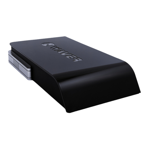
Waver AIRFINITY WAC52LTE User manual

1
WAC52LTE/WAC52LTE+
QUICK START GUIDE
READ CAREFULLY BEFORE USING THE DEVICE

2
Your satisfaction is our top priority.
Propose a feature that will be useful to be
added on Waver AirFinity in the upcoming
software updates at features@wavertech.eu
Thank you
for choosing our product!
Package Contents
1. Waver® AirFinity Outdoor 4G LTE Router
2. 2.4/5GHz Omni Antenna (dual band) x2
3. LTE 4G Antenna
4. Power Adapter 24V 1.2A
5. Redundant Gigabit PoE Injector
6. Metal Straps x2
7. Quick Start Guide
Requirements
• OS: Windows 7 or newer, Linux, Mac OS X or Android
• Web Browser: Chrome (Recommended), Mozilla Firefox or
Apple Safari
Internet Connection: 4G LTE (microSIM) or Ethernet

CONTENTS
- Package Contents 4
- Safety Information 5
- Hardware Overview 6
- Hardware Installation 6
- Device Management 11
- Firmware Update & Reset 28
- Multilingual Instructions 30
- Warranty and Returns 33
- Declaration of Conformity 35
- Technical Specications 38
• Read this manual thoroughly before using
Waver AirFinity
• To ensure proper use of the device, make sure
to read “Safety Information” page
• After reading, keep it in a readily accessible
place for future reference

4
Package Contents
2.4/5GHz
Dual-Band Omni
Antenna (7/9dBi) x2
Redundant Gigabit
PoE Injector Metal Clamps x2
LTE 4G Antenna
(2 dBi) Power Adapter
24V 1.2A
Quick Start
Waver® AirFinity Outdoor 4G LTE Router

5
Safety Notices
Electrical Safety Information
1. Read, follow, and keep these instructions
2. Heed all warnings
3. Only use attachments/accessories specied by the manufacturer.
1. Compliance is required with respect to voltage, frequency, and cur-
rent requirements indicated on the manufacturer’s label. Connection to
a different power source than those specied may result in improper
operation, damage to the equipment or pose a re hazard if the limita-
tions are not followed.
2. There are no operator serviceable parts inside this equipment. Ser-
vice should be provided only by a qualied service technician.
3. This equipment is provided with a PoE Injector which has a safety
ground wire intended for connection to a ground.
a. Always use shielded Cat5e FTP or upper category Ethernet cable
with grounded RJ45 Connectors.
b. The equipment requires the use of the ground wire as a part of
the safety certication, modication or misuse can provide a shock
hazard that can result in serious injury or death.
c. Contact a qualied electrician or the manufacturer if there are ques-
tions about the installation prior to connecting the equipment.
d. Protective earthing is provided by the Included PoE Injector. Building
installation shall provide appropriate short-circuit backup protection.
e. Protective bonding must be installed in accordance with local
national wiring rules and regulations.
WARNING: Do not use this product in location that can be
submerged by water.
WARNING: Avoid using this product during an electrical
storm. There may be a remote risk of electric shock from
lightning

6
1. Antenna Connector (N-Female) - 2.4/5GHz
2. WAN/PoE In GbE Port (waterproof)
3. microSIM Port (waterproof)
4. Antenna Connector (N-Female) - LTE 4G
5. GUEST GbE Port – Guest Extension (waterproof)
6. Antenna Connector (N-Female) - 2.4/5GHz
Hardware Overview
1 2 3 4 5 6

7
Install antennas
Plug and screw in the N-Type WiFi and LTE antennas.
Please make sure the antennas are installed properly.
Hardware Installation

8
SIM Card Installation (optional)
Ethernet Cable Installation
Remove the transparent protective cap
from microSIM port.
Insert microSIM Card by performing the
push-in procedure as seen in the image.
Check if the card is installed properly
and remains in position.
Re-install the protective cap.
Run the shielded FTP Ethernet cable (CAT5e or Upper) in order
to connect the device with the indoor PoE Injector. Connect the
WAN Ethernet Port of the AirFinity (outdoors) with the PWR+-
DATA OUT of the Power Injector (indoors). If you are going to
use the Ethernet for providing Internet connectivity to AirFinity,
connect DATA-IN with the Internet Gateway (e.g. ISP Router).
Use straight-through Ethernet
Cable wiring (T-568B)
TO AIRFINITY
ISP ROUTER
optional

9
Outdoor Installation
Install the Waver AirFinity outdoors in a vertical pole using the
included metal clamps as shown in the image below.
indoor
optional
GND
Ground the installation
Connect PoE Injector with ground by using the GND Terminal
WARNING: Call an electrician or contact manufacturer if you
are not sure how to proceed on this step.

10
Powering
Connect the DC Power supply with the Power Injector and the
power supply to the main socket.
Secondary Power Input
Using the terminal block, you can connect a secondary power
source such as a battery/solar output within the voltage
range 12-28VDC.
Depending on your installation needs, this can be used as a
main or as backup power source
Boot the device
Boot process will start as soon as you will connect a power
source to the PoE Injector.
After powering, the system will be up and running in approxi-
mately 2 minutes.
a. During the boot process (it takes about 1 minute
and 30 seconds to boot up)
b. During Reboot process
c. During Factory Reset process
d. During Firmware update process
NEVER DISCONNECT POWER OR TURN OFF THE DEVICE
IMPORTANT
- Turning off the device or disconnecting power source during
the above processes, can corrupt ash image and can make
the device unbootable!

11
Device can be managed via any web browser. Access to the
web interface is available from Local WiFi Interfaces (local
network) and WAN/Internet Port.
Web Management tools
1. Administration Interface
Default access:
http://192.168.10.1
Username: admin
Password: waver
Device Management
2. User manager Interface
User Manager “admin” password: waver
Default access: http://192.168.10.1/userman/
(same account with administration interface)
User Manager “manager” password: password
Default access: http://192.168.10.1/userman/
(limited access account for accessing User Manager)

12
3. Discount Coupon Code manager
Discount Code Manager password: password
Default access: http://192.168.10.1/coupons/
To access this panel, you are going to need a unique
customization key. This key is being generated separately
for each device.
4. Customization Panel (Whitelabeling)
5. Live! Menu (QR Menu)

13
Live! Menu “admin” password: waver
(same password with device’s admin password)
Live! Menu “manager” password: password
(same password with Coupon Code manager)
Default access: http://192.168.10.1/order/admin/
The main administration interface. Networking, guest ses-
sion, captive portal settings, customization and management
for the local device. General system settings and statistics
are also available here.
1. Administration Interface
1. To login to the the Administration interface connect wire-
lessly to a Local WiFi interface.
Defaults Local WiFi Networks:
Local2G (WPA2 Key: wavertech2)
Local5G (WPA2 Key: wavertech5)
2. Launch your Web browser and type http://192.168.10.1 in
the address eld.
Press enter (PC) or return (Mac).
Note: Your computer needs to be on the 192.168.10.x
subnet. If you have DHCP Client enabled on your network
adapter, it will receive an IP Address automatically. If not,
you will need to set a static IP address in the 192.168.10.2 -
192.168.10.254 range.

14
3. Enter“admin” as username and “waver” as password,
select the proper region and time zone (correct time zone
is very important for database synchronization and other
critical device functions). Read carefully the end user license
agreement. If you agree with all the terms you can check the
“I agree the terms and conditions” checkbox and click on the
“Login button”.
4. The MAIN page of conguration interface will appear.
You are logged in and you can congure your Waver
AirFinity router.
An overview on the administration interface
MAIN: Shows general guest user data statistics,
device information, interface throughput and con-
nectivity status.

WAN | LAN
Congures Internet connectivity type, Firewall and
Port forwarding, Website Filtering and Local Net-
work Settings.

16
WIRELESS
Shows wireless interface information and statistics,
Congures interface and wireless networks settings.

17
GUEST NETWORK
Congures network parameters for guest network.
It shows information regarding devices on the guest
network.

CAPTIVE PORTAL
Congures the guest landing page appearance and
the way guests are authenticated on your guest
network.

19
GUEST USERS | STATISTICS
Analytic guest user data statistics. The synchroniza-
tion of user data with third party or external systems
can also be managed on this page.

20
CΑMPAIGN MANAGER
With Campaign Manager you can congure the
router to automatically send a greeting Email or
SMS to the guest after the st login, a “Welcome
Back” message on second visit etc. You can also
schedule the router to automatically create and
deliver an Email or SMS coupon.
This manual suits for next models
1
Table of contents
Other Waver Network Router manuals