waves system ID-AL My Video Player VP320 User manual

ID-AL My Video Player VP320 and VP330
Quick Start Guide V1.2
1 Introduction
This guide explains ho to quickly start up the My Video Player for a first use. For further information and
help on this product, see the support page of the My Video Player on .id-al.com.
The My Video Player range is composed of standalone and interactive players that allo the playback of audio,
picture, video 4K HDR UHD and HTML5 / JavaScript contents. These contents can be stored in an internal
memory, on a microSD card, or on a USB flash drive. The playback can be programmed to start automatically, to
follo a schedule, or to respond to external events (infrared remote control, input contacts, RS-232, TCP/IP,
JavaScript, or REST).
2 Hard are Description
1 Headphone stereo audio output, standard 3.5 mm (TRS) jack
2 Infrared sensor
3 Clickable knob (volume)
4 Status LED
5 0 dBu line-level stereo audio output, RCA connectors
6 Class D amplified speaker stereo audio output, pluggable terminal
blocks
7 USB Host 2.0 for USB flash drive and touch screen, type-A
receptacle
8 Standalone opto-isolated input and po er supply output, pluggable
terminal block
9 HDMI audio/video output, type-A (standard) receptacle connector
10 microSD card slot
11 10/100 Mbps Ethernet, RJ45 connector
12 USB Host 2.0 for USB flash drive and touch screen, type-A
receptacle
13 External DC po er supply chassis socket
14 RS-232 serial link and po er supply output, pluggable terminal block
15 8 opto-isolated input contacts and po er supply output, pluggable
terminal block
16 8 MOSFET outputs and po er supply output, pluggable terminal
block
17 5 V DC output, pluggable terminal block
Button Description
Short press: standby/ ake-up. Long press: po er off / restart.
Mute/unmute.
Skip 10 seconds back ard/for ard.
Play/pause.
Stop Playback.
Red Green Yello Blue Programmable buttons: by default, play folder 1 to 6, respectively.
Toggle on-screen information display.
Exit.
In menu context: up/do n. In playback context: next/previous folder.
In menu context: left/right. In playback context: previous/next file.
In menu context: validate selection. In playback context: toggle on-screen
information display.
Toggle on-screen menu display.
Back.
Increase/decrease the volume.
When selecting a value, typically ith a slider control, skip many values.
In menu context: digit characters. In playback context: play folder 0 to 9.
Dot character.
Erase previous character.
© 07/16/2020, Waves System – 14 rue Philippe Lebon, 44980 Saint-Luce-sur-Loire, France – +33 (0) 2 40 78 22 44 – sales@ system.com
ID-AL My Video Player – Quick Start Guide V1.2
3 Connecting the Hard are Interfaces
First, make sure that the player is off (mains adapter unplugged). Then, connect the hard are interfaces according
to the needs:
Interface Usage
microSD and USB If needed, prepare a storage device, then plug it into the player. See 5 Programming the Player .
Video output Compatible ith a ide range of HDMI displays.
Audio outputs Connect non-amplified speakers to the amplified speaker output, or amplified speakers to the line-level audio
output, or a headphone to the headphone output, or use the HDMI audio.
Ethernet net ork Player time synchronization using NTP, access to the player storage through FTP, media stream playback,
playback synchronization for a group of players, player control using TCP/IP, display of eb content hosted
remotely, configuration and local control ith the remote administration.
Po er supply outputs On the pluggable terminal blocks: po er supply for accessories requiring little po er.
RS-232 serial link Control of other devices, such as video projectors or PLCs, or control of the player from another device using a
dedicated protocol.
Input and output contacts Connect them as explained in the follo ing sections.
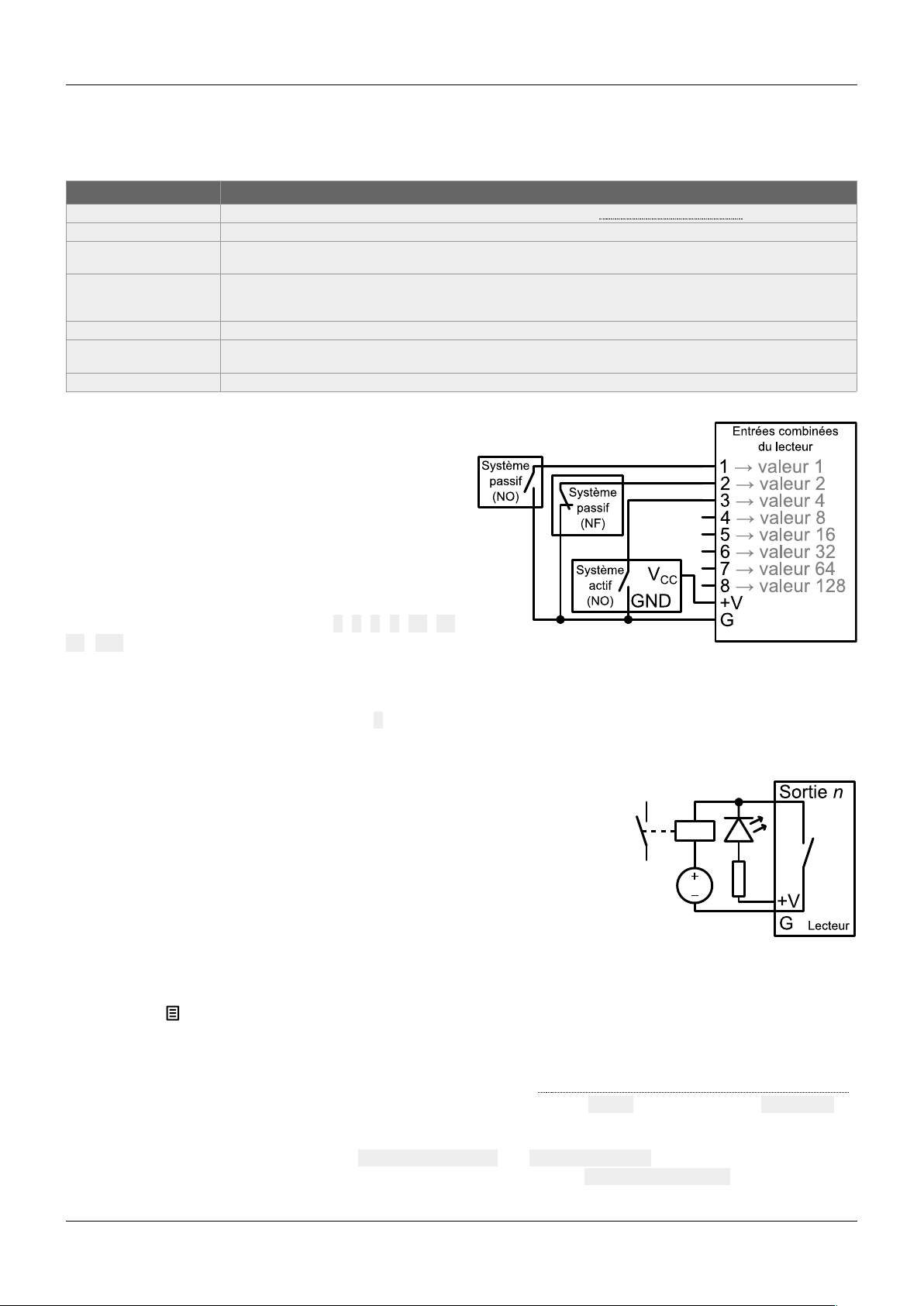
3.1 Input Contacts
The 1 + 8 input contacts can be configured to trigger
various actions, such as playback control, standby, ake-
up, or sending a serial frame. Devices behaving like
s itches can be connected bet een these inputs and the
ground of the player (e.g.: push-button, presence sensor,
relay, PLC, SensoPad, IRPad). Active devices can use
the po er supply pass-through. Each input can be
configured as normally open or closed.
The 1st to 8th combined inputs are respectively associated
ith the follo ing values hen active: 1, 2, 4, 8, 16, 32,
64, 128. The action taken for these inputs depends on
their combination, defined as the sum of the values of all the active inputs, hich is simply the value of an input if it
is the only one active. If more than 8 triggering devices are needed, the ID-AL Ext15In board or a diode-based
circuit can be used to get more than 8 combinations from these devices.
By default, the standalone input plays folder 1, and the 8 combined inputs play the folder numbered ith the active
combination.
3.2 Output Contacts
The 8 outputs behave like normally-open s itches bet een each contact and the
ground of the player (up to 500 mA per output). They can be used to operate
devices such as po er relays, motor controllers, lights, or players.
4 Starting the Player
•After having connected all the required interfaces, turn the player on by plugging the mains adapter. The
status LED should quickly get red, hich signals that the player is booting.
•Wait for the status LED to turn green, hich indicates that the player is ready.
•Press on the remote control to display the on-screen menu, then configure the player according to the
desired settings such as system language, net ork, date and time, security of the access of the FTP server
and the remote administration, etc.
•When the player is connected to a local net ork, the configuration is possible ith an internet bro ser. To do
this, enter the address of the player in the address bar (see 6 Identify the Player on the Ethernet Net ork ).
Once connected to the remote administration of the player, enter admin as identifier and password as
pass ord.
•In order to make sure that the player benefits from the latest features and improvements, it is possible to
perform a firm are update from System settings → System update. If an Internet connection is
available, it is recommended to follo the automatic procedure using Check for update.
© 07/16/2020, Waves System – 14 rue Philippe Lebon, 44980 Saint-Luce-sur-Loire, France – +33 (0) 2 40 78 22 44 – sales@ system.com

ID-AL My Video Player – Quick Start Guide V1.2
5 Programming the Player
5.1 General Rules
The player is programmed by organizing media files and other files in a
specific ay (see the example opposite) on a storage device (microSD
card, USB flash drive, or internal storage). The external storage devices
must initially be formatted using one of the supported file systems (FAT32 is
recommended), after hich it can be filled using a computer then plugged
into the player, or first plugged into the player then filled through FTP
(internal storage, FTP only) (default username and pass ord: idalftp for
both) (see 6 Identify the Player on the Ethernet Net ork).
•S STEM folder: contains configuration files and other files used by
the system.
•Playback folders, numbered from 0 to 999: contain the usual
multimedia files (MP4, MKV, MOV, STREAM, WAV, MP3, M4A,
OGG, JPG, PNG, BMP, etc.). These folders are prefixed or not ith
zeros. They are used as an identifier for commands. (Sub-folders
excluded)
•S NCHRO folder: contains the multimedia files to be played hen
receiving a synchronized playback request. These files must be
numbered. (Sub-folders excluded)
•WWW folder: contains the HTML5/JavaScript pages and all files
necessary for their operation.
The playback folders can have an arbitrary orking name after their number. Various directives, called tags, can be
added bet een square brackets. These tags can be used to control the playback, the volume, and the output
contacts, to send serial frames, or to block commands from a configurable list of sources. For the complete tag
specification, see the user guide.
The multimedia files inside the playback folders can also have tags. They can be numbered to ease sorting in
sequential playback mode.
5.2 HTML5/JavaScript Content
Execution of HTML5/JavaScript code and display of overlaid
eb pages on the video playback is provided by an
embedded eb server. An additional JavaScript API allo s
you to control the playback from HTML5/JavaScript content.
The creation and implementation of eb content is done in 3 steps:
Step 1 Step 2 Step 3
Create eb content
Create HTML5 / JavaScript eb pages (place
the local content to www folder). If necessary,
use the JavaScript API to control the player
from eb pages.
Indexed eb content
Add the URLs of eb pages by editing the
web-config.json file or by using the
dedicated tool from the remote administration
of the player.
Add file tags
Add to folders or files the dedicated tags to
sho or hide eb content ([WEBS x], [WEBE
x], [WEBS OFF], [WEBE OFF])
For more information on this topic, see the user guide.
5.3 Streaming
In order to play a video or audio stream, a file ith the extension .stream must be placed into a playback folder
like a regular media file. This file describes the stream and gives its net ork address. See the user guide for
details.
© 07/16/2020, Waves System – 14 rue Philippe Lebon, 44980 Saint-Luce-sur-Loire, France – +33 (0) 2 40 78 22 44 – sales@ system.com

ID-AL My Video Player – Quick Start Guide V1.2
5.4 Scheduler
In order to schedule commands, a file named scheduler.tm2 must be generated on a computer thanks to the
Scheduler soft are (do nloadable from .id-al.com), then placed into the S STEM folder.
5.5 Serial Frames
The serial frames that the system needs to send must be listed in a file named serial.txt, hich can be created
ith a ra text editor on a computer according to a specific syntax, then placed into the S STEM folder. This file can
also be created and edited using the player remote administration (see 4 Starting the Player). The transmission of
the serial frames can be programmed using folder or file tags, or a direct command order. See the user guide for
details.
5.6 Further Configurations
Various aspects of the playback and of the usage scenario can be configured in the on-screen menu ( ), under
Playback engine settings and Scenario settings, respectively. Contrary to all the other settings, the
scenario settings are linked to the specific use case programmed on the storage device. That’s hy they are saved
by the player in S STEM\scenario-config.json on the current storage device in order to make them easily
portable to other players.
5.7 Playback Start Synchronization
This feature allo s to synchronize the start of playback of a designated file ithin a group of players over the
net ork, using the selected multicast UDP port:
•With the [S NCHROxxx] file tag (e.g.: Video A[S NCHRO001].mp4), the player sends the xxx
synchronization request to all the other players ithin the group.
•The players receiving the xxx synchronization request look for a file ith a name beginning ith xxx in the
S NCHRO folder (e.g.: 001 Video B.mp4). All the players of the group then start the playback
synchronously.
•For all the players in the group, in the setup on-screen menu ( ), select Scenario settings →
Playback start synchronization, then enable Playback start synchronization and change
the Multicast UDP port value if needed (by default: 44830).
5.8 Receive Serial, TCP/IP, or REST commands
The player can be controlled on an Ethernet net ork using TCP/IP (port 65079) or REST. It can also be controlled
on the RS-232 serial link (from 9600 to 115200 baud) in exclusive mode (send commands and receive states) or
in “Daisy Chain” mode (send commands only). The protocol hich defines the 3 bytes command frames is identical
for the TCP/IP and the serial link. The references of the REST API for controlling the player (methods, requests and
responses) are specified in dedicated documentation. See the user guide for details.
6 Identify the Player on the Ethernet Net ork
The IP address of the player is indicated in the on-screen menu ( → System settings → Network →
Connected) ith the infrared remote control. It is also possible to identify the player on a net ork using its mDNS
name EVP380-sernum, sernum being the serial number indicated under About in the on-screen menu ( ).
7 Factory Reset
This feature restores the default factory settings and erases the content of the player internal storage. This is done
in the on-screen menu ( → System settings → Storage & reset → Factory reset, then follo the on-
screen instructions.
8 Further Steps
Go to the support page of the My Video Player on .id-al.com for the advanced features, further information,
documentation, firm are, soft are, and examples.
© 07/16/2020, Waves System – 14 rue Philippe Lebon, 44980 Saint-Luce-sur-Loire, France – +33 (0) 2 40 78 22 44 – sales@ system.com
Other manuals for ID-AL My Video Player VP320
1
This manual suits for next models
1
Table of contents
Other waves system DVD Player manuals


