WAVESYS WSIL-1204-GT2-SFP2 Instructions for use

⚫WSIL-1204-GT2-SFP2
⚫WSIL-1204-GT2-SFP2-Extd

FCC Notice
This equipment has been tested and found to comply with the limits for a Class-A digital device,
pursuant to Part 15 of the FCC rules. These limits are designed to provide reasonable protection
against harmful interference in a residential installation. This equipment generates, uses, and can
radiate radio frequency energy. It may cause harmful interference to radio communications if the
equipment is not installed and used in accordance with the instructions. However, there is no
guarantee that interference will not occur in a particular installation. If this equipment does cause
harmful interference to radio or television reception, which can be determined by turning the
equipment off and on, the user is encouraged to try to correct the interference by one or more of
the following measures:
•
Reorient or relocate the receiving antenna.
•
Increase the separation between the equipment and receiver.
•
Connect the equipment into an outlet on a circuit different from that to which the receiver
is connected.
•
Consult the dealer or an experienced radio/TV technician for help.
Caution: Any changes or modifications not expressly approved by the grantee of this device could
void the user's authority to operate the equipment.
CE Mark Warning
This is a Class-A product. In a domestic environment this product may cause radio interference in
which case the user may be required to take adequate measures.
This document is the current official release manual. Please check our website
(www.wavesysglobal.com) for any updated manual or contact us by e-mail

Contents
Overview.............................................................................................................................................................................................. 1
Key Features .................................................................................................................................................................................. 1
Package Contents........................................................................................................................................................................ 2
Safety Precaution......................................................................................................................................................................... 2
Hardware Description .................................................................................................................................................................... 3
Physical Dimensions................................................................................................................................................................... 3
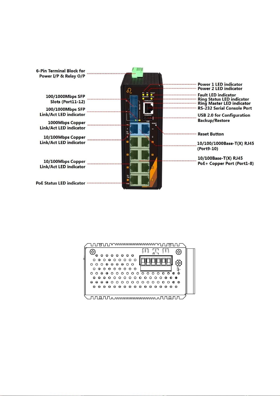
Front Panel ..................................................................................................................................................................................... 4
Top View ......................................................................................................................................................................................... 4
LED Indicators ............................................................................................................................................................................... 5
Ethernet Ports ............................................................................................................................................................................... 7
Cabling............................................................................................................................................................................................. 8
Wiring the Power Inputs.........................................................................................................................................................10
Wiring the Fault Alarm Contact ...........................................................................................................................................11
Grounding Note.........................................................................................................................................................................11
Mounting Installation...................................................................................................................................................................12
DIN-Rail Mounting ...................................................................................................................................................................12
Wall Mounting............................................................................................................................................................................14
Hardware Installation ...................................................................................................................................................................16
Installation Steps .......................................................................................................................................................................16
Maintenance and Service ...........................................................................................................................................................17
Trouble Shooting ...........................................................................................................................................................................18

1
Overview
This series is rated IP30 and installation by DIN Rail. Each unit of this industrial managed fast
Ethernet switch series has 8*10/100Tx with 8*IEEE 802.3at compliant ports (30W/port) and
2*10/100/1000Tx RJ45 and 2*100/1000x SFP slots, suitable for applications that require high
bandwidth and long distance communication.
In order to prevent unregulated voltage, this series provides high EFT and ESD protection. This also
allows it to function in harsh environments, as well as support power redundancy with a dualpower
input design with reverse polarity protection. The built-in relay warning function alerts users about
occurring power failures.
With one model having an operating temperature of -10 to 65°C, and another with a wide
operating temperature of -40 to 75°C, this series is designed to meet any needs for industrial
application and harsh environments.
Key Features
Interface & Performance
•
Copper port support auto MDI/MDI-X function
•
Embedded 8*10/100Tx with 8* PoE PSE 30W/Port, and 2*10/100/1000Tx RJ45, and
2*100/1000x SFP Slots
•
Store-and-forward switching architecture
•
8K MAC Address Table
•
Supports 9.6Kbytes Jumbo Frame
•
4Mbits memory buffer
Power Input
•
Redundant power DC 48-55V with connective 1*6-pin removable terminal bloc
•
Max. current 5.5A
•
Max. PoE output: 240W
Certification
•
CE/FCC
•
EN61000-6-4 / EN61000-6-2
•
UL 61010-1 / UL61010-2-201
Operating Temperature
•
Standard operating temperature model: -10°C ~ 65°C
•
Extended operating temperature model (–T): -40°C ~ 75°C
Case/Installation
•
IP30 protection
•
Installation in pollution degree to environment
•
DIN-Rail and Wall mount design

2
Package Contents
•
1 -WSIL-1204-GT2-SFP2(-Extd)x 1
•
2 - Wall mounting brackets and screws x 1
•
3 - Quick installation guide x 1
Safety
Precaution
Attention
If the DC voltage is supplied by an external circuit, please use a protection device on the power
supply input. Supply by UL Listed industrial use power. The industrial Media Converter’s hardware
specs, ports, cabling information, and wiring installation will be described within this user manual.
Warning Labels
The caution label means that you should check the certain information on user manual when
working with the device. (Shown in Figure 1.1)
Figure 1.1: Caution Label
This warning label is on the device, and means that the surface of the device is hot. (Shown
in Figure 1.2)
Figure 1.2: Hot Surface Warning Label

3
Hardware Description
Physical Dimensions
Figure 2.1, below, shows the physical dimensions ofWSIL-1204-GT2-SFP2 series.
(W x H x D) is 54mm x 142mm x 99mm
Figure 2.1:WSIL-1204-GT2-SFP2 Series Physical Dimensions

4
Front Panel
The front panel of theWSIL-1204-GT2-SFP2 series industrial PoE+ gigabit managed fast Ethernet
switch is shown below in Figure 2.2.
Top View
Figure 2.2: The Front Panel ofWSIL-1204-GT2-SFP2 Series
Figure 2.3, below, shows the top panel of theWSIL-1204-GT2-SFP2 series switch that is equipped
with one 6-pin removal terminal block connector for dual DC power inputs (48-55VDC).
Figure 2.3: Top Panel View ofWSIL-1204-GT2-SFP2
Series

5
LED Indicators
There are LED light indicators located on the front panel of the industrial Ethernet switch that
display the power status and network status. Each LED indicator has a different color and has its
own specific meaning, see below in Table 2.1.
LED
Color
Description
P1
Green
On
Power input 1 is active
Off
Power input 1 is inactive
P2
Green
On
Power input 2 is active
Off
Power input 2 is inactive
FAULT
Green
On
No event happened
Red
Off
1. Power input 1 or 2 is inactive
2. Port link-down/Broken
MASTER
Green
On
ERPS Owner Mode (Ring Master) is ready
Off
ERPS Owner Mode is not active
RING
Green
On
ERPS Ring Network is active and works well
Flashing
ERPS Ring works abnormally or misconfigure
Off
ERPS Ring Network is not active
L/A
(SFP Port 11-12)
Green
On
Connected to network, 1000Mbps
Flashing
Networking is active
Off
Not connected to network
Amber
On
Connected to network, 100Mbps
Flashing
Networking is active
Off
Not connected to network
1G
(LAN Port 9-10)
Green
On
Connected to network, 1000Mbps
Flashing
Networking is active
Off
Not connected to network
10/100
(LAN Port 9-10)
Green
On
Connected to network, 10/100Mbps
Flashing
Networking is active

6
Off
Not connected to network
10/100
(LAN Port 1-8)
Green
On
Connected to network with 10/100Mbps
Flashing
Networking is active
Off
Not connected to network
PoE
(LAN Port 1-8)
Green
On
Supplying power to the powered-device
Off
Not connected to a Powered Device
Table 2.1: LED Indictors forWSIL-1204-GT2-SFP2 Series
Caution: "P1/P2" is the abbreviation for "Power 1/Power 2", "L" is for "Link", and "A" is for
"Activity".

7
Ethernet Ports
RJ-45 Ports (Auto MDI/MDIX)
The RJ-45 ports are auto-sensing for 10Base-T, 100Base-TX or
1000Base-T devices connections. Auto MDI/MDIX means that the
switch can connect to another switch or workstation without
changing the straight-through or crossover cabling. See the figures as
below for straight-through and crossover cabling schematics.
10/100BASE-T(X) RJ-45 Pin Assignments (Table 2.2)
Crossover Cable
Straight Through Cable
Pin Number / Signal
Pin Number / Signal
Pin Number / Signal
Pin Number / Signal
1 / RX+
3 / TX+
1 / RX+
1 / TX+
2 / RX-
6 / TX-
2 / RX-
2 / TX-
3 / TX+
1 / RX+
3 / TX+
3 / RX+
6 / TX-
2 / RX-
6 / TX-
6 / RX-
Table 2.2
1000BASE-T RJ-45 Pin Assignments (Table 2.3)
Crossover Cable
Straight Through Cable
Pin Number / Signal
Pin Number / Signal
Pin Number / Signal
Pin Number / Signal
1 / TP0+
3 / TP1+
1 / TP0+
1 / TP1+
2 / TP0-
6 / TP1-
2 / TP0-
2 / TP1-
3 / TP1+
1 / TP0+
3 / TP1+
3 / TP0+
4 / TP2+
7 / TP3+
4 / TP2+
4 / TP3+
5 / TP2-
8 / TP3-
5 / TP2-
5 / TP3-
6 / TP1-
2 / TP0-
6 / TP1-
6 / TP0-
7 / TP3+
4 / TP2+
7 / TP3+
7 / TP2+
8 / TP3-
5 / TP2-
8 / TP3-
8 / TP2-
Table 2.3
Note: “+” and “-”signs represent the polarity of the wires that make up each wire pair.

8
Cabling
Use the four twisted-pair, category 5e, or the above cabling for RJ-45 port connections. The cable
between the switch and the link partner (switch, hub, workstation, etc.) must be less than 100
meters (328 ft.) long.
The small form-factor pluggable (SFP) is a compact optical transceiver used in optical
communications for both telecommunication and data communication applications.
Caution: Please employ optional optical transceiver (SFP/Fixed Fiber) that complies with IEC
60825-1 and classified as Class 1 laser product.
To connect the transceiver and LC cable, please follow below steps:
Step 1. Insert the SFP transceiver module into the SFP slot as shown below in Figure 2.4. Notice
that the triangle mark is at the bottom of the SFP slot. Figure 2.5 shows SFP transceiver
module was inserted.
Figure 2.4: Transceiver to the SFP Module
Figure 2.5: Transceiver Inserted

9
Step 2. Insert the fiber cable of the LC connector into the transceiver as shown below in Figure
2.6.
Figure 2.6: LC Connector to the Transceiver
To remove the LC connector from the transceiver, please follow the steps shown below:
Step 1. Press the upper side of the LC connector from the transceiver and pull it out to release as
shown below in Figure 2.7
Figure 2.7: Remove LC Connector

10
Step 2. Push down the metal clasp and pull the transceiver out by the plastic part as shown
below in Figure 2.8
Figure 2.8: Pull Out from the SFP Module
Wiring the Power Inputs
Please follow the below steps to insert the power wire.
Step 1. Insert the positive and negative wires into the PWR1 (V1+, V1-) and PWR2 (V2+, V2-)
contacts on the terminal block connector as shown below in Figure 2.9.
Figure 2.9: Power Terminal Block
Step 2. Tighten the wire-clamp screws to prevent the wires from loosening, as shown below in
Figure 2.10.
Figure 2.10: Power Terminal Block

11
Note:
Only use copper conductors, 125°C, tighten to 5 lbs.
The wire gauge for the terminal block should range between 18~20 AWG.
Wiring the Fault Alarm Contact
The fault alarm contact is in the middle of the terminal block connector as the picture shows
below in Figure 2.11. By inserting the wires, it will detect the fault status including power failure
or port link failure (managed industrial switch only) and form a normally open circuit. An
application example for the fault alarm contact is shown below in Figure 2.11.
Figure 2.11: Wiring the Fault Alarm Contact
Caution: The wire gauge for the terminal block should range between 12 ~ 24 AWG.
If only using one power source, jumper Pin 1 to Pin 5 and Pin 2 to Pin 6 to eliminate
power fault alarm.
Grounding Note
Grounding and wire routing help limit the effects of noise due to electromagnetic interference
(EMI). Run the ground connection from the ground screw to the grounding surface prior to
connecting devices. The grounding screw symbol is shown blow in Figure 2.12.
Figure 2.12: Grounding screw
Caution: Using a shielded cable achieves better electromagnetic compatibility.

12
Mounting Installation
DIN-Rail
Mounting
The DIN-Rail is pre-installed on the industrial Media Converter from the factory. If the DIN-Rail is
not on the industrial Media Converter, please see Figure 3.1 to learn how to install the DIN-Rail on
the Media Converter.
Figure 3.1: The Rear Side of the Media Converter and DIN-Rail Bracket
Follow the steps below to learn how to hang the industrial Media Converter.
Step 1. Use the screws to install the DIN-Rail bracket on the rear side of the industrial Media
Converter.
Step 2. To remove the DIN-Rail bracket, do the opposite from Step 1.
Step 3. After the DIN-Rail bracket is installed on the rear side of the Media Converter, insert the
top of the DIN-Rail on to the track as shown below in Figure 3.2.

13
Figure 3.2: Insert the Media Converter on the DIN-Rail
Step 4. Lightly pull down the bracket on to the rail as shown below in Figure 3.3.
Figure 3.3: Stable the Media Converter on DIN-Rail
Step 5. Check if the bracket is mounted tightly on the rail.
Step 6. To remove the industrial Media Converter from the rail, do the opposite from the above
steps.

14
Wall Mounting
Follow the steps below to mount the industrial Media Converter using the wall mounting bracket
as shown below in Figure 3.4.
Step 1. Remove the DIN-Rail bracket from the industrial Media Converter by loosening the
screws.
Step 2. Place the wall mounting brackets on the top and bottom of the industrial Media
Converter.
Step 3. Use the screws to screw the wall mounting bracket on the industrial Media Converter.
Step 4. Use the hook holes at the corners of the wall mounting bracket to hang the industrial
Media Converter on the wall.
Step 5. To remove the wall mount bracket, do the opposite from the steps above.
Figure 3.4: Remove DIN-Rail Bracket from the Switch and Install the Wall Mount Bracket

15
Below, in Figure 3.5 are the dimensions of the wall mounting bracket.
Figure 3.5: Wall Mounting Bracket Dimensions

16
Hardware Installation
Installation Steps
This section will explain how to installWSIL-1204-GT2-SFP2 series.
Installation Steps
Step 1. Unpack the industrial Media Converter from the original packing box.
Step 2. Check if the DIN-Rail bracket is screwed on the industrial Media Converter.
•
If the DIN-Rail is not screwed on the industrial Media Converter, please refer to the DIN-Rail
Mounting section for DIN-Rail installation.
•
If you want to wall mount the industrial Media Converter, please refer to the Wall Mounting
section for wall mounting installation.
Step 3. To hang the industrial Media Converter on a DIN-Rail or wall, please refer to the
Mounting Installation section.
Step 4. Power on the industrial Media Converter and then the power LED light will turn on.
•
If you need help on how to wire power, please refer to the Wiring the Power Inputs section.
•
Please refer to the LED Indicators section for LED light indication.
Step 5. Prepare the twisted-pair, straight-through category 5 cable for Ethernet connection.
Step 6. Insert one side of the RJ-45 cable into Media Converter’s Ethernet port and on the other
side into the networking device’s Ethernet port, e.g. switch PC or server. The Ethernet
port’s (RJ-45) LED on the industrial Media Converter will turn on when the cable is
connected to the networking device.
•
Please refer to the LED Indicators section for LED light indication.
Step 7. Insert one side of the SFP cable into Media Converter’s SFP port and on the other side into
the networking device’s SFP port, e.g. switch or server. The SFP port’s LED on the industrial
Media Converter will turn on when the cable is connected to the networking device.
•
Please refer to the LED Indicators section for LED light indication.
Step 8. When all connections are set and the LED lights all show normal, the installation is
complete.

17
Maintenance and Service
•
If the device requires servicing of any kind, the user is required to disconnect and remove it
from its mounting. The initial installation should be done in a way that makes this as convenient
as possible.
•
Voltage/Power lines should be properly insulated as well as other cables. Be careful when
handling them so as to not trip over.
•
Do not under any circumstance insert foreign objects of any kind into the heat dissipation holes
located in the different faces of the device. This may not only harm the internal layout, but
might cause harm to user as well.
•
Do not under any circumstance open the device for any reason. Please contact your dealer for
any repair needed or follow the instructions within the manual.
•
Clean the device with dry soft cloth.
This manual suits for next models
1
Table of contents
Other WAVESYS Network Hardware manuals
Popular Network Hardware manuals by other brands

Cisco
Cisco ONS 15454 Procedure guide

Linksys
Linksys MX4300 user guide

Matrix Switch Corporation
Matrix Switch Corporation MSC-HD81DEL product manual

C&T Solution
C&T Solution ACO-6000-KBL Series user manual

HiLook
HiLook NVR-100MH-D/W Series quick start guide

Nortel
Nortel Meridian Installation and maintenance guide

Alcatel-Lucent
Alcatel-Lucent 5620 Planning guide

Matrix Switch Corporation
Matrix Switch Corporation MSC-V1616S product manual

ADTRAN
ADTRAN DSU III TDM manual

Motorola
Motorola DIMETRA MTS 2 Installation, Configuration and Basic Service Manual

Canon
Canon Vb-C60 - Ptz Network Camera Setup guide

ADTRAN
ADTRAN FXO+ DUAL VOICE user manual