Wavetrend R500HA User manual

iAutomate.com
Installation Manual
R500HA Long Range RFID
Reader
Developed by:
KRM Technology, Inc
dba iAutomate.com
4305 State Bridge Road
Suite 103-251
Alpharetta, GA 30022
Phone: 678-388-9508
Toll Free: 888-949-1388
Fax: 678-388-9508
Email: [email protected] or [email protected]
http://www.iautomate.com
2005 iAutomate.com

iAutomate.com
TABLE OF CONTENTS
Product Overview............................................................................................. 3
1.2 Network Wiring and Power..................................................................... 3
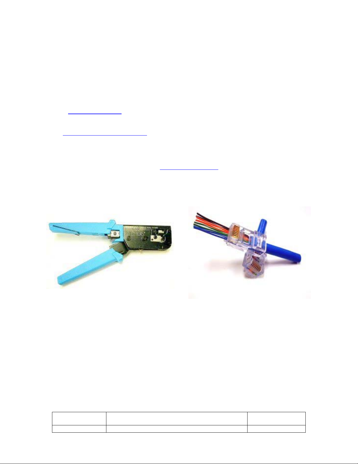
1.3 Tooling and Connectorization ................................................................. 5
2.1 RF Basics Relating to the R500HA RFID Reader......................................... 5
2.1 RF Basics Relating to the R500HA RFID Reader (Cont’d) ............................ 6
2.2 RF Range and Antenna Polarization ......................................................... 6
2.3 Antenna Placement and Signal Strength Testing ..................................... 10
3.1 The RFID Tags ................................................................................... 11
3.1.1 The T800 Tag Primary Use: ................................................................. 11
3.1.2 The T501 Tag Primary Use: Windshields, Personnel, Non Metallic Assets ... 11
3.1.3 The T100 Tag Primary Use: ................................................................. 12
3.1.4 The T1200 Wrist Band Tag Primary Use:................................................ 12
3.1.5 The T700 KeyFOB Primary Use:............................................................ 13
4.1 HomeSeerPlug-In Installation ........................................................... 13
4.3 HomeSeerPlug-In and R500HA System Configuration ........................... 15
4.3.1 Adding Readers.................................................................................. 17
4.3.2 Receiver ID ....................................................................................... 18
4.3.3 Location and Name............................................................................. 18
4.3.4 RSSI (Received Signal Strength Indicator) ............................................. 18
4.3.5 GAIN………………………………………………………………………………………………………………….18
4.3.6 Min Timeout (Minimum Timeout and Additional Timeout) ......................... 18
4.3.7 Adding Tags ...................................................................................... 19
4.3.8 Address …………………………………………………………………………………………….……………..19
4.3.10 Name ….…………………………………………………………………………………………………………..19
4.3.11 Additional Timeout ............................................................................. 20
4.3.12 Saving Changes and Additional Control Buttons ...................................... 20
4.3.13 Enable Debug Logging ........................................................................ 20
4.3.14 Reset/Restart Everything..................................................................... 20
4.3.16 Update/Save ..................................................................................... 21
4.4 HomeSeerPlug-In Triggers and Conditions .......................................... 21
4.4.1 Triggers ............................................................................................ 21
4.4.2 Enters Reader’s Range ........................................................................ 21
4.4.3 Leaves Reader’s Range ....................................................................... 21
4.4.4 Has been in Reader’s Range for a Time Period ........................................ 21
4.4.5 Update/Save ..................................................................................... 22
4.4.6 Tag in Reader’s Range is Moving........................................................... 22
4.4.7 Tag Goes Into/Leaves Security Alarm (Removed or Present)..................... 22
4.4.8 Tag’s RSSI at Reader is Greater Than/Less Than (Value).......................... 23
4.4.9 Has Been Out of Readers Range for a Time Period................................... 23
4.4.11 Keyfob Button in Reader’s Range is Pushed ............................................ 23
4.4.12 Conditions......................................................................................... 24
4.5.1 Additional Information – Startup/Shutdown............................................ 24
4.5.2 Shutdown ......................................................................................... 25
4.6 Error Messages .................................................................................. 25
4.7 Ten Common Mistakes ........................................................................ 27
5.2 Tag and Reader Worksheet .................................................................. 29
5.3 Licenses and Disclaimer ...................................................................... 30
Part Number 2005 iAutomate.com 4/11/05
R500HA R500HA Reader Installer Manual Page 2 of 31

iAutomate.com
Product Overview
The R500HA Long Range RFID Reader is a uniquely addressable passive antenna that can
be daisy chained together on one CAT5 COM Port. Up to 254 unique addresses are possible.
Custom manufactured for iAutomate.com for home automation (HA) applications, the HA
Edition R500HA Long Range RFID Reader is used in conjunction with HomeSeerSoftware
or CrestronSystems (Sold Separately) and is specifically designed for detection (or
absence) of people, vehicles, and personal assets. The R500HA RFID (Radio Frequency
IDentification) Reader provides near field or long-range coverage for real-time detection of
people, pets, vehicles or anything else you can associate with one of the various RFID Tags.
The R500HA Reader communicates with either:
• A PC via a standard COM Port Running HomeSeerSoftware
• Serial Port of a Crestron System
Additional Readers can be daisy chained to permit many Readers on one CAT5 wire system.
Each Reader is range settable via software to adjust for the requirements of the room or
application. Range adjustable antennas can be discretely concealed in walls, ceilings, and
doorways to identify and track Tag activity. The R500HA can simultaneously read multiple
RFID Tags at ranges of up to 450 feet (free air), and can also register and report the
disappearance or unauthorized movement of individual RFID Tags. This model is for use
ONLY with Crestron systems or HomeSeerv1.7 or later. A FREE HomeSeerplug-in or
Crestronmodule is included with the Installer Setup Kit.
1.2 Network Wiring and Power
The R500HA Readers are connected together in a daisy chain topology. That is, Reader 1 is
connected to Reader 2, which, in turn, is connected to Reader 3, etc. Up to 254 Readers can
be interconnected in this manner. Readers are joined to one another with a single cable,
utilizing four wires to carry both data and power. Reader-to-Reader communication is
accomplished over one pair of wires via RS485 protocol; while a second pair of wires carries
power. The network of Readers can be connected to either a PC’s standard RS232 serial port
or a Crestron System (running the Crestron Software Module).
Power
RS485
Power
RS485
12345
Data Flow
Power
RS485
Power
RS485
Power
PC
RS232 via
Installer Setup
Ki
t
Part Number 2005 iAutomate.com 4/11/05
R500HA R500HA Reader Installer Manual Page 3 of 31

iAutomate.com
1.2 Network Wiring and Power (cont’d)
Be certain to follow all local and national codes when installing network wiring. Avoid
installing wiring near electrical and electronic equipment, high-powered equipment, motors,
and other potential sources of RF interference.
Do NOT use standard four-pair (eight wire) Ethernet Wiring Connections or
DAMAGE will result. Refer to Figure 2 or Figure 3 and ONLY connect the 4 wires
between Readers:
• Power
• Ground
• RS485+
• RS485-
These connections have been arranged in such a way that the cable forms a straight-
through connection and does not require twisting or changing of any wires between
Readers. This makes the installation of this network very simple. Since each RS485
connection between Readers is theoretically a separate network, distances between them
can be up to 2000 ft, according to the RS485 standard, depending on the quality of the
cable used. RS485 termination resistors are included in each Reader’s circuitry and
therefore do not need to be added.
The network operates at 57,600 baud, with data being sent bidirectionally. The ReaderNet
may be supplied with power from multiple points within the network, but when more than
one power supply is used; the supplies must be interconnected via the ground line.
Only the SPS1212 Power Supply may be used to power the Network. (Using any other
power supply will void the Reader warranty). Up to ten Readers can be powered with a
single SPS1212 Power Supply, which delivers 1.2A@12VDC.
Pin Pin Name Description
1. NOT USED NOT USED
2. NOT USED NOT USED
3. PWR +12VDC
4. GND Ground
5. RS485+ Non-Inverted
RS485
6. RS485- Inverted RS485
7. NOT USED NOT USED
8. NOT USED NOT USED
Right RJ45 Connector
Part Number 2005 iAutomate.com 4/11/05
R500HA R500HA Reader Installer Manual Page 4 of 31
Pin Pin Name Description
1.
RS232 RXD RS232 RXD to PC TXD
2.
RS232 TXD RS232 TXD to PC RXD
3. PWR +12VDC
4. GND Ground
5. RS485+ Non-Inverted RS485
6. RS485- Inverted RS485
7. NOT USED NOT USED
8. NOT USED NOT USED
Left RJ45 Connector
Note: Pins 1 and 2 used ONLY on 1st Reader.
On the first Reader, this is handled by the
R5000HA-ISK PC Breakout Cable

iAutomate.com
1.2 Network Wiring and Power (cont’d)
The SPS1212 Power Supply is included with the R500HA Installer Setup Kit. Also included
with the Installer Setup Kit: PC Interface cable for connecting the first R500HA Reader to
the PC, 30-Day HomeseerTrial, FREE iAutomate R500 Plug-in for Homeseer, and
CrestronSoftware Module for CrestronSystems. For specific pin outs and color codes,
please download the latest diagram from our website.
1.3 Tooling and Connectorization
iAutomate.com highly recommends the EZ-RJ45 Crimp Tool and Connectors for making
trouble-free Reader terminations the very first time. This high-quality crimp tool is designed
to quickly crimp and cut the wires of the EZ-RJ45 ® Connector.in a single, simple operation.
The crimp tool also works on most other brands of RJ45 Connectors. No home automation
installer should be without this time saving tool and a bag of EZ-RJ45 Connectors.
Figure 4
2.1 RF Basics Relating to the R500HA RFID Reader
A typical radio-communication system is comprised of two main components, namely a
transmitter (Tx) and a receiver (Rx). The transmitter generates electrical oscillations at a
given radio frequency and the receiver detects these electrical oscillations if it is tuned to
the same frequency. The frequency used is called the carrier wave.
In general, FM radio works the same way that AM radio works; the difference is in how the
carrier wave is modulated, or altered. With AM radio, the amplitude, or overall strength, of
the signal is varied to incorporate the digital information. With FM, the frequency (the
number of times each second that the current changes direction) of the carrier signal is
varied.
Part Number 2005 iAutomate.com 4/11/05
R500HA R500HA Reader Installer Manual Page 5 of 31

iAutomate.com
FM signals have an advantage over AM signals. Though both signals are susceptible to slight
changes in amplitude, with an AM broadcast, these changes result in static, while with an
FM broadcast, slight changes in amplitude don't generate static. Since the FM signal is
conveyed through changes in frequency, the FM receiver can just ignore changes in
amplitude. On the other hand, AM has a distinct advantage over FM in terms of power
consumption. AM signals can be transmitted at a much lower power consumption level than
any other modulation at 433 MHz. It is purely for reasons of power conservation (longer
battery life) that AM modulation is used for the RFID Tags.
2.1 RF Basics Relating to the R500HA RFID Reader (Cont’d)
In the earth’s atmosphere, the physical characteristics of air can cause variations in the
speed at which radio waves travel. These variations can be a cause of problems in any
communication system. This is why you might notice different performances from the same
RF System on different days as the weather or atmospheric conditions change. Many natural
events (such as storms, or excessive solar activity) and man-made electrical devices can
adversely affect RF Transmissions.
Because data is transmitted in digital form from the Tag to the Reader, the norm to use is
either Amplitude Shift Keying (ASK) or Frequency Shift Keying (FSK). The R500HA RFID
Reader uses ASK as the preferred method solely because of the power saving characteristics
of the ASK technique of data coding.
2.2 RF Range and Antenna Polarization
The distance an RF Transmission will travel is primarily determined by the transmitter’s
output power and the receiver and antenna’s power (GAIN) and is influenced by
environmental conditions and structures. Although the level of available power is the main
determinant of transmission range, the manner and efficiency in which that power is
deployed will also play a role.
The design of the transmitter’s antenna determines the shape of the field delivered. The
field (or wave) delivered from an antenna extends into the space surrounding it, and its
strength diminishes with respect to distance. In any space free of obstructions or
absorption, the strength of the field reduces in inverse proportion to the square of the
distance. Effective range is also ** influenced by the angle (polarization) between the
transmitter’s and receiver’s antennas. ** For an RF wave travelling through an area in
which it can be reflected off of the ground or from metal obstacles, the reduction in strength
can be quite considerable. Where different travel paths are created in this manner, the
phenomenon is termed “multi-path attenuation.” Absorption of RF Energy due to the presence of
moisture, both in the atmosphere and in objects in the environment can further influence effective range.
It is VERY important to determine how the environment, both internal and external, can
influence the range of the R500HA RFID Readers before permanently installing wiring or
mounting the Readers. We recommend temporary wiring and temporary mounting of
antennas as a method of range testing the components while connected to the PC to
determine the best locations for optimum signal strength and range.
Part Number 2005 iAutomate.com 4/11/05
R500HA R500HA Reader Installer Manual Page 6 of 31

iAutomate.com
Part Number 2005 iAutomate.com 4/11/05
R500HA R500HA Reader Installer Manual Page 7 of 31

iAutomate.com
2.2 RF Range and Antenna Polarization - Continued
It is far better to find a Reader location that will afford maximum range, and then tune the
Reader down if necessary, as opposed to selecting a weak location and then trying to boost
the signal, which might be impossible.
Here is an example of the coverage pattern of the R500HA Reader when using the supplied
dipole (whip) antenna. This is how the pattern would look with the Reader mounted
vertically. The tip of the antenna is where X & Y intersect in the center of the “Donut.”:
Note that the pattern is both horizontal AND vertical. Care must be taken to place readers is
such a way that tags are not detected from a floor above or floor below.
Figure 5
Part Number 2005 iAutomate.com 4/11/05
R500HA R500HA Reader Installer Manual Page 8 of 31

iAutomate.com
Look at what happens to the pattern if you lay the R500HA Reader flat, or at a 90 Degree
angle from vertical:
Figure 6
Effective range is influenced by the angle (polarization) between the transmitter’s and
receiver’s antennas. Because of this, the same holds true for the orientation of the Tags as
for the Reader. By orienting the Tags at different angles (polarization) to the antenna, you
can impact the range and performance of the Tags. For Maximum range, the angle of
polarization of the Tag and R500HA RFID Reader should be the same.
In some instances the wiring between Readers can function as part of the antenna. For this
reason it is required that field wiring be installed in such a way that Tags do not come in
contact or near contact with the field wiring in the course of normal activity. Since such
interference cannot be avoided, ferrite chokes are supplied which will snap over each of the
CAT 5 cables at each reader as shown in Figure 7.
Figure 7
Part Number 2005 iAutomate.com 4/11/05
R500HA R500HA Reader Installer Manual Page 9 of 31

iAutomate.com
2.3 Antenna Placement and Signal Strength Testing
Suggested Reader Locations for Localized Automation
Mount Readers on floor joist below Room or in Attic Above Room
Figure 8
Initial trial with temporary wiring for signal strength showing Reader locations centralized under internal
rooms but favoring outside (driveway) wall of Garage to maximize Automobile Tag Range. A variety of
antennas are available for longer range and exterior applications. Note that the R500HA Reader antenna
may be removed when only near field detection is required, or the desired range cannot be lowered
enough via software.
Part Number 2005 iAutomate.com 4/11/05
R500HA R500HA Reader Installer Manual Page 10 of 31

iAutomate.com
3.1 The RFID Tags
There are four basic Tags available at the time of the publishing of this manual. Each RFID
Tag performs a little bit differently from the other. In addition to the different styles of Tags,
most are available with optional features such as: Tamper Detect, which transmits a tamper
alarm, and Motion Sensing, which transmits data when the RFID Tag experiences even
slight motion.
3.1.1 The T800 Tag Primary Use:
Place on the outside of Metallic Assets, such as toolboxes, metalized windshields, metal
carts, metal trash cans as well as plastics or fiberglass containing a high metallic content
(such as laptop and desktop computer systems, office machines, hospital equipment,
telephones, etc.), as RF signals will have a very low transmission range, if the Tag is placed
within a metalized object.
T800 Standard RFID Tag
T800-TD RFID Tag with Tamper Detect and Magnet
T800-MS RFID Tag with Motion Sensor and Tamper Detect
3.1.2 The T501 Tag Primary Use:
Windshields, Personnel, Non Metallic Assets
T501 Standard RFID Tag
T501-TD RFID Tag with Tamper Detect and Magnet
T501-MS RFID Tag with Motion Sensor and Tamper Detect
Part Number 2005 iAutomate.com 4/11/05
R500HA R500HA Reader Installer Manual Page 11 of 31

iAutomate.com
The RFID Tags (Cont’d)
3.1.3 The T100 Tag Primary Use:
Use for covert mounting under the hood of a car or behind the grill. Small size permits
installation in an optional RF-transparent weatherproof enclosure. Antenna is external to the
Tag and can be “trimmed” by altering its length.
T100 Standard RFID Tag
T100-TD RFID Tag with Tamper Detect and Magnet
T100-MS RFID Tag with Motion Sensor and Tamper Detect
3.1.4 The T1200 Wrist Band Tag Primary Use:
Use for patient monitoring, pet monitoring, personnel monitoring, child monitoring in theme
parks. This Tag is removable and is secured by strapping, as used in hospital admissions or
theme parks. The Wrist Band Tag is NOT waterproof but ultrasonically sealed.
T1200 Standard RFID Tag
T1200-MS RFID Tag with Motion Sensor
Part Number 2005 iAutomate.com 4/11/05
R500HA R500HA Reader Installer Manual Page 12 of 31

iAutomate.com
3.1.5 The T700 KeyFOB Primary Use:
The KeyFOB Tag is generally used for key tagging, although it may be used in other applications such as
personnel monitoring and has a built-in panic button. The KeyFOB Tag is NOT waterproof but is
ultrasonically sealed.
T700 Standard RFID KeyFOB Tag
T700-MS RFID Key Fob Tag with Motion Sensor
4.1 HomeSeerPlug-In Installation
The installation of the R500HA plug-in for HomeSeeris straightforward, and is similar to that of some
other HomeSeerplug-ins. The plug-in consists of the single Wise installer file RFIDinstall.exe, which is
executed to launch the installer. This program installs the necessary files and some sample RFID Scripts
and also registers the components with the operating system. The Plug-In can also be installed via the
HomeSeerUpdater.
Once the R500HA plug-in is installed on your HomeSeersystem, it must be activated for
use within HomeSeerbefore you can use it. If you installed the R500HA plug-in via the
HomeSeerUpdater, this step will not be necessary. To activate the plug-in, go to the
HomeSeerWindows User Interface and click “View” on the menu bar. On the View menu,
find “Options” and select it. The HomeSeerconfiguration option pages will be displayed,
with the default page (Default) appearing. Using the tabs at the top of the configuration
pages, select “Interfaces” to display the interface configuration options. The interfaces
configuration page will look similar to Figure 9:
Part Number 2005 iAutomate.com 4/11/05
R500HA R500HA Reader Installer Manual Page 13 of 31

iAutomate.com
Figure 9
At the bottom of the screen, find the “Plug-Ins (RF,I/O,Security,Custom)” section – this is
where we will add the iAutomate RFID plug-in to activate it within HomeSeer. Click on the
drop down list under “Select device to add:” and find the iAutomate RFID plug-in. If the
plug-in was installed correctly, you should find it in the list similar to this section of the
screen shown in Figure 10:
Figure 10
Part Number 2005 iAutomate.com 4/11/05
R500HA R500HA Reader Installer Manual Page 14 of 31

iAutomate.com
After selecting this plug-in, click “OK” to close the interface tab. You will be reminded to
restart HomeSeerto activate the changes you have made. Shut down HomeSeerand
restart it to continue setting up the plug-in. After restarting, return to the interface
configuration screen. Your Plug-Ins list should look similar to Figure 11:
Figure 11
4.3 HomeSeerPlug-In and R500HA System Configuration
When HomeSeeris restarted, your HomeSeerlog will display this error:
Error initializing Custom Interface: Goto \rfid_config and set the COM port.
The error may also appear like this if the plug-in has been partially or incorrectly
configured:
2/21/2005 8:46:16 PM~!~iAutomate RFID~!~Error 8002, Invalid port number on line 0
2/21/2005 8:46:16 PM~!~iAutomate RFID~!~InitIO Error 8012, The device is not open on line 0
These error messages are normal as the plug-in does not know which COM port to use for
the plug-in. To correct this and to set up your Readers and Tags, go to the configuration
screen using your web browser. (See HomeSeerdocumentation for details.)
If you do not use custom links at the top of your HomeSeerweb pages, the plug-in will
add itself to the list of links that appears with the title “R500 Configuration”. Select this link.
If you do use custom links, and plug-in registered links are not automatically added to your
custom links, you can go to the configuration page by entering the URL directly in your web
browser. The configuration page is at the address rfid_config. As an example, if your
HomeSeersystem has the web server configured for port 82, you would enter the address
similar to Figure 12:
Figure 12
Part Number 2005 iAutomate.com 4/11/05
R500HA R500HA Reader Installer Manual Page 15 of 31

iAutomate.com
The first configuration setting to make is the COM port that the first R500HA Reader is
connected to on your HomeSeerPC. At the top of the configuration, find the COM port
setting (as shown in Figure 14):
Figure 14
Enter the number for the COM port on your system that the R500HA network is connected
to, then click on the “Update/Save” button at the bottom of the screen to save your
changes.
At this point you could use the “Reset/Restart Everything” button to begin using the plug-in
with your Reader network, but without any Readers or Tags configured, it will not have
much benefit, so please continue.
4.3.1 Adding Readers
The first section of the configuration screen after communications is “Tag Readers”. This
section is used to define the Readers that you have on your R500HA network. It is
important to note that only ONE Reader can be added at a time between restarts/resets of
the plug-in. Only one Reader should be configured at a time, because the plug-in
enumerates (examines) the R500HA network to find the single new Reader that exists on
the network for which it does not already have a configuration (Reader ID) applied. When it
finds this Reader, it takes the configuration settings for this Reader and applies it to the new
Reader. Node IDs are assigned automatically based upon position in the network, thus the
addition of a node between two existing nodes will change the Node IDs for all of the
Readers. For this reason, a secondary addressing technique is used that does not change
once the address is assigned to the Reader. In order to guarantee that the secondary
address information is applied to the correct Reader, only one Reader can be added at a
time between restarts of the plug-in.
To add a Reader, fill in the information on the row that ends with the “Add” button. The
values you can enter are described in the following sections; refer to the example Reader
configuration image in Figure 15 as needed.
Figure 15
Part Number 2005 iAutomate.com 4/11/05
R500HA R500HA Reader Installer Manual Page 17 of 31

iAutomate.com
4.3.2 Receiver ID
The Receiver ID is automatically generated by the plug-in for new Readers, but it may be
changed at a later date. The Reader ID must be unique across the network of Readers.
Once the Reader ID has been programmed into a Reader, it may be moved in its location
amongst the other Readers on the network and still retain its identity and associated
configuration.
4.3.3 Location and Name
The Location and Name fields are for your own identification of the Reader at this time – no
HomeSeerdevices are created using these names, but the location and name fields follow
the HomeSeernomenclature in case future revisions create devices to work with the plug-
in.
4.3.4 RSSI (Received Signal Strength Indicator)
The RSSI indicates the strength of the signal from a Tag when it is received at a Reader.
This configuration setting for the Reader determines the MINIMUM value of RSSI before the
Reader will acknowledge the Tag’s signal. For example, a Tag that is very close to a Reader
may send a signal that is received by the Reader measuring an RSSI of 130. When that
same Tag is 350’ away from the Reader, the measured RSSI of the received Tag signal may
only be 50. If the Reader RSSI setting is 60, the Tag signal from 350’ away will not be
acknowledged by the Reader, whatsoever. Although the various Reader and Tag
combinations will have different characteristics for RSSI, the current R500HA Readers and
Tags generally have RSSI values between 30 and 130. Readers that you wish to configure
for the maximum range should be set to zero, and anything 30 or higher will begin to affect
the range at which Tags are detected.
4.3.5 GAIN
The receiver GAIN setting sets a characteristic of the receiver’s radio that affects the range
of the Tags it can “hear.” If you are seeking the highest possible range of Tags to be
received, set this to HIGH, otherwise set it to LOW , change to HIGH only if you cannot get
the range you seek for the application of the Reader.
4.3.6 Min Timeout (Minimum Timeout and Additional Timeout)
When a Reader no longer hears a Tag signal, it is considered “absent” from the Reader. In a
single-Reader, single-Tag system, updates from the Reader will occur approximately at 0.8
second intervals, but updates increase dramatically with multiple Readers and multiple
Tags. In a large system, a Tag signal may not be received for a few seconds, so the timeout
parameter helps prevent the plug-in from assuming a Tag is absent when it actually is not.
When the last time a Tag has been “seen” and the current time are different from the total
timeout period (or more), then the Tag is removed from the list of Tags associated with that
Reader, and the “Tag is absent from Reader” trigger (if there is one used in the system) is
raised. The total timeout period consists of the minimum timeout, which is set for each
Reader (this configuration setting) and the additional timeout that is configured with each
Tag. This setting is in seconds, and the minimum value for this setting is 2 seconds.
Part Number 2005 iAutomate.com 4/11/05
R500HA R500HA Reader Installer Manual Page 18 of 31

iAutomate.com
If the Reader you are configuring is used for applications such as a “sign of life” where a Tag
can come into and out of range of a Reader frequently without adversely affecting your use
of it, then set this to its minimum value. If you are using the Reader for applications such as
lighting or music, and you do not want to change the music or lighting frequently or in
error, then set this to a higher value.
Likewise, as with the Reader timeout, the additional timeout associated with the individual
Tags can help customize the system. If the Tag is one that does not move very often or
moves slowly, you can set the additional timeout to a value perhaps 3 to 5 seconds. If, on
the other hand, the Tag is on something expected to move in and out of range of many
Readers very often, you can leave the additional timeout at its default value of zero.
4.3.7 Adding Tags
The plug-in will only acknowledge signals from Tags that you have configured in the system.
The Tag’s address number can be found on the Tag itself. The portion of the configuration
screen that you add Tags to the system with is shown in Figure 16:
Figure 16
4.3.8 Tag ID
The Tag’s ID Number is unique to each tag and is found on a sticker on the Tag. There
should only be one of any given address in your R500HA RFID system. The Tag’s address
can be anywhere from 1 to 10 digits.
4.3.9 Tag Model
The tag model must be set to the model number of the tag being used. The model number is usually on
stamped on the back of the tag. Selecting the proper model of tag enables tag specific triggers (such as
Keyfob button pressed) to be utilized in various events.
4.3.10 Name
The name assigned to the Tag is for your identification only. When setting up triggers and
conditions, the Tag name prevents you from having to remember the Tag’s address.
Part Number 2005 iAutomate.com 4/11/05
R500HA R500HA Reader Installer Manual Page 19 of 31

iAutomate.com
4.3.11 Additional Timeout
Please see section topic Min Timeout (Minimum Timeout and Additional Timeout) 4.3.6 Min Timeout
(Minimum Timeout and Additional Timeout) for information on this setting. The timeout setting here is for
the Tag, and is added to the timeout setting of the Reader when it comes within range.
4.3.12 Saving Changes and Additional Control Buttons
The bottom of the R500HA RFID configuration screen has additional control buttons and the
“Save/Update” button to save changes made to Tags and Readers. This section looks like
Figure 17:
Figure 17
4.3.13 Enable Debug Logging
The “Enable Debug Logging” button changes to “Disable Debug Logging” if debug logging is
enabled. Pressing this button causes the plug-in to begin logging very detailed plug-in
information to the file iAutomateRFID.log in the HomeSeerroot folder. This information
may be necessary to assist support personnel resolve issues with the plug-in. Turning this
on unnecessarily will cause the plug-in to slow and the log file to grow in size very rapidly.
4.3.14 Reset/Restart Everything
There are two circumstances when the “Reset/Restart Everything” button should be used:
1.) If you are adding Readers to the network, you can configure the new Reader, add the
new Reader to the network, and then press this button to reset the network and allow the
plug-in to discover and configure the new Reader. 2.) If at startup the network does not
reset fast enough for the plug-in to discover all of the Readers, you can press this button to
attempt a restart without having to shut down HomeSeer. Note: Since this will remove all
of the discovered Readers from the network, Tag/Reader triggers and conditions can be
affected.
4.3.15 Suspend Plug-In - Resume Plug-In
These two buttons provide additional control of the plug-in to suspend RFID activity or
Part Number 2005 iAutomate.com 4/11/05
R500HA R500HA Reader Installer Manual Page 20 of 31
Table of contents