AR-837-E / EF
V200929
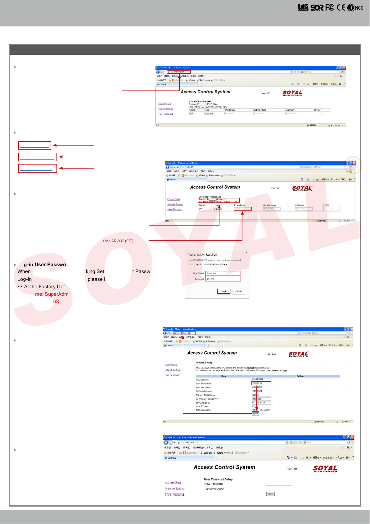
ACCESS & INDUSTRIAL CONTROL
B.
或
1
2
CN7
CN8
CN3
CN13
CN6
CN5
CN4
AR-837i
AR-MDL-721V
AR-WG-HID
AR-837i
AR-MDL-721V
AR-WG-HID
8
8
2
1
321
CN4
CN4
CN6
CN6
CN3
CN3
CN8
CN8
CN13
CN13
CN5
CN5
9DO
837-E
3DO
837-EE
Contents
2Terminal Cables
The communication wires and power line should NOT be bound in the same conduit or tubing.
Don’t equip reader and lock with the same power supply. The power for reader may be unstable when the lock is activating, that may cause a
malfunction in the reader.
The standard installation: Door relay and lock use the same power supply, and reader should use another independent power supply.
Use AWG 22-24 Shielded Twist Pair to avoid star wiring, CAT 5 cable for TCP/IP connection
1.Tubing:
2.Wire selection:
3.Power supply:
1Products 3Tools 4Optional
Notice
Connector Table (1)
(HID RF Module)
(HID RF Module)
(TCP/IP Module)
(TCP/IP Module)
(Voice Module)
(Voice Module)
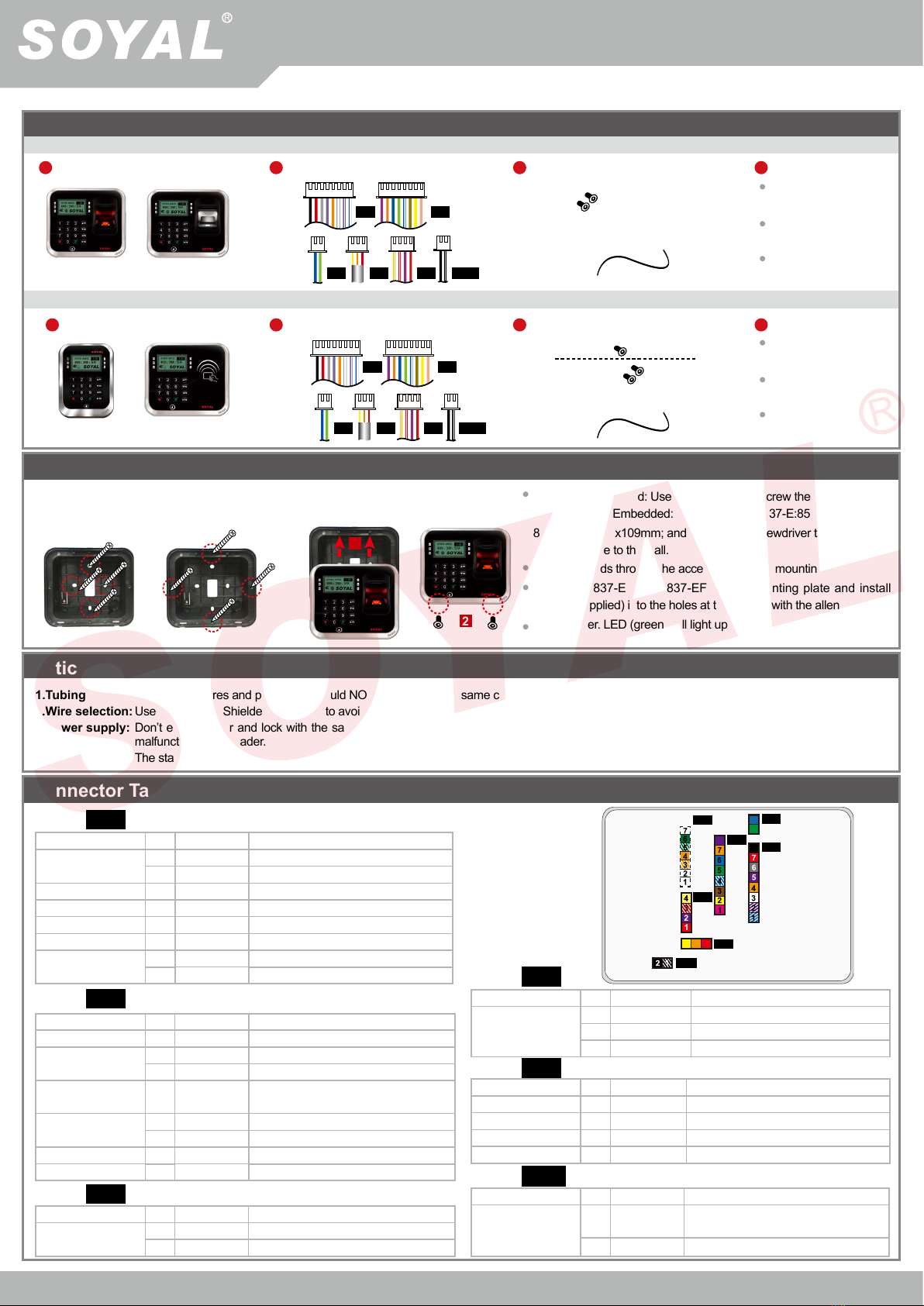
Wire Application Wire Color Description
Lock Relay 1Blue White (N.O.)DC24V1Amp
2
Purple White
(N.C.)DC24V1Amp
Lock Relay COM 3White (COM)DC24V1Amp
Door Contact 4Orange Negative Trigger Input
Exit Switch 5Purple Negative Trigger Input
Alarm Relay 6Gray N.O./N.C. Optional (by jumper)
Power 7Thick Red DC 12V
8Thick Black DC 0V
Cable:
Wire Application Wire Color Description
RS-485 for Lift
Controller
1Thick Green RS-485(B-)
2Thick Blue RS-485(A+)
Cable: Wire Application Wire Color Description
Door Bell 1Black White Transistor Output Max. 12V/100mA
(Open Collector Active Low)
2Black DC 0V
Cable:
Wire Application Wire Color Description
Beeper 1Pink Beeper Output 5V/100mA, Low
LED 2Yellow Red LED Output 5V/20mA, Max
3Brown Green LED Output 5V/20mA, Max
Door Output 4Blue White Transistor Output Max. 12V/100mA
(Open Collector Active Low)
Wiegand 5Thin Green Wiegand DAT: 0 Input
6Thin Blue Wiegand DAT: 1 Input
WG Door Contact
7Orange Negative Trigger Input
WG Exit Switch 8Purple Negative Trigger Input
Cable:
2Terminal Cables
1Products 3Tools 4Optional
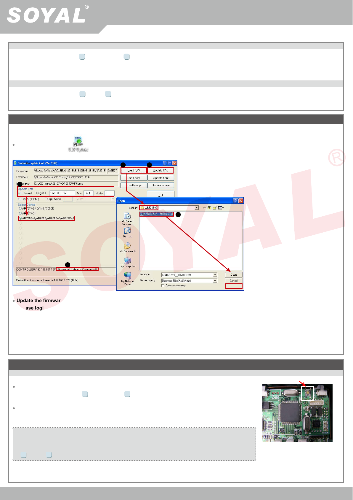
A-1.Surface Mounted: Use a screwdriver to screw the mounting plate
to the wall. A-2.Embedded: To dig a hole for 837-E:85mmx113mm /
837-EF:128mmx109mm; and then, use a screwdriver to screw the
mounting plate to the wall.
Pull cable ends through the access hole in the mounting plate.
Attach AR-837-E or AR-837-EF to the mounting plate and install
screws (supplied) into the holes at the bottom with the allen key.
Apply power. LED (green) will light up with one beep.
Installation
AR-837-EF:Fingerprint
AR-837-E/ EE
Wire Application Wire Color Description
Reserved 1 Red --
Security trigger signal
2Purple Security trigger signal Output
Arming 3 Red White Arming Output
Duress 4 Yellow White Duress Output
Cable:
Wire Application Wire Color Description
Anti-Tamper Switch 1Red N.C.
2Orange COM
3Yellow N.O.
Cable:
Water proof Strip
Water proof Strip
Screws
Screws
Or
A-1.Surface
Mounted
A-2.Embedded
CN4
CN3
CN8
CN13
CN6
CN5
AR- 837-E
AR- 837-EE Screws