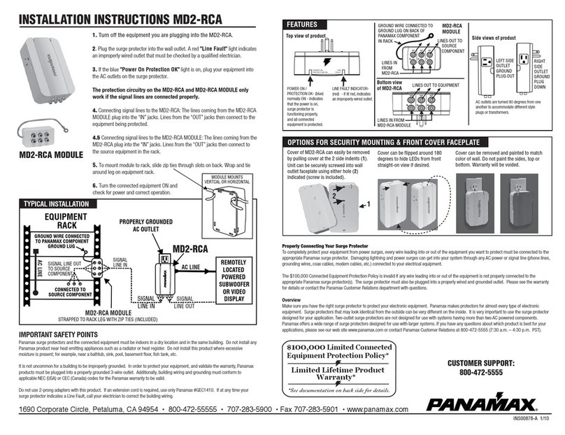
Wavetronix Click 65 Series User manual

Click 65x Series
USER GUIDE

Click 65x
USER GUIDE
Springville, Utah
801.734.7200
www.wavetronix.com

WX-500-0310
01/22
© 2022 Wavetronix LLC. All Rights Reserved.
Wavetronix, SmartSensor, Click, Command, and all associated product names and logos are trademarks of Wavetronix
LLC. All other products or brand names as they appear are trademarks or registered trademarks of their respective
holders.
Protected in the US by patents viewable at www.wavetronix.com/legal. Protected by Canadian Patent Nos. 2461411;
2434756; 2512689; and European Patent Nos. 1435036; 1438702; 1611458. Other US and international patents pending.
The Company shall not be liable for any errors contained herein or for any damages arising out of or related to this docu-
ment or the information contained therein, even if the Company has been advised of the possibility of such damages.
This document is intended for informational and instructional purposes only. The Company reserves the right to make
changes in the specifications and other information contained in this document without prior notification.
FCC Part 15 Compliance: The Wavetronix SmartSensor sensors comply with Part 15 of the Federal Communications Com-
mission (FCC) rules which state that operation is subject to the following two conditions: (1) this device may not cause
harmful interference, and (2) this device must accept any interference received, including interference that may cause
undesirable operation. FCC compliance statements for applicable optional modules are to be found in the module speci-
fications. Unauthorized changes or modifications not expressly approved by the party responsible for compliance with the
FCC rules could void the user’s authority to operate this equipment.
Disclaimer: The advertised detection accuracy of the Wavetronix SmartSensor sensors is based on both external and
internal testing, as outlined in each product’s specification document. Although our sensors are very accurate by industry
standards, like all other sensor manufacturers we cannot guarantee perfection or assure that no errors will ever occur in
any particular applications of our technology. Therefore, beyond the express Limited Warranty that accompanies each
sensor sold by the company, we oer no additional representations, warranties, guarantees or remedies to our customers.
It is recommended that purchasers and integrators evaluate the accuracy of each sensor to determine the acceptable
margin of error for each application within their particular system(s).

5Introduction
6 Using this guide
1 QUICK START GUIDE
7Installing the Click 65x
8Configuring using the front panel
8Configuring the sensor
10 Configuring using the web interface
10 Using the PROPERTIES tab
10 Using the SENSORS tab
11 Using the CHANNELS tab
11 Using the VERIFICATION tab
11 Using the HEALTH tab
2 HARDWARE AND INSTALLATION DETAILS
14 Making connections
14 Connecting AC power
15 Terminating the SmartSensor 6-conductor cable
16 Connecting data to the trac controller
16 Toggling power to sensors
17 Using the control bus to configure the sensors
17 Using the T-bus
3 OLED PANEL
20 Device Info
21 Network Setup
22 BIU Setup
23 Verify Output
24 Utilities
4 WEB INTERFACE
26 Properties tab
27 Sensors tab
CONTENTS

28 Channels tab
30 Adding multiple sensor channels
32 Using the MMU tab
32 Copying and pasting BIUs
33 Verification tab
34 Health tab
35 Graphs tab
35 Data Summary
36 Count Details
38 Arrival Profile
39 Other functions
39 Export/Import configuration
39 Upgrade page
40 Admin page
5 SDLC
45 TS1/TS2 controllers
46 TS2 controllers and Click 65x devices

Introduction •5
Introduction
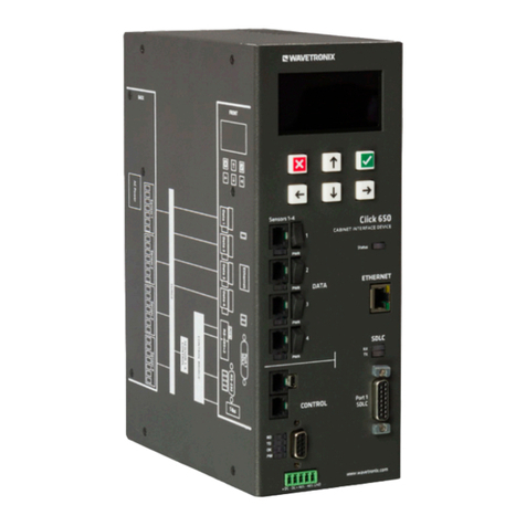
The Click 65x series consists of two devices, the Click 650 and
656. They are robust cabinet interface devices that provide
power, surge protection, and streamlined communication to up to
four (Click 650) or six (Click 656) SmartSensor Matrix or Advance
sensors. They are designed to serve as replacements for the
Wavetronix full and segmented backplates, providing the same
functionality with a smaller cabinet footprint.
Figure 1. The Click 650 (left) and 656 (right)
These devices provide up to 64 channels of sensor detection
output, either to contact closure devices or directly to the trac
controller through SDLC. Utilizing the SDLC connection to compati-
ble controllers potentially removes the need for detector racks and

6 • Click 65x User Guide
rack cards, allowing for more cabinet space savings. The provided
64 channels of detection output—which, in a cabinet using tradi-
tional equipment, would have required an unrealistic 16 to 32 rack
of cards—allows for additional sensor functionality such as data
collection and advanced analytics beyond the standard stop bar
and advance detection.
They also provide an Ethernet port for direct connection to
local networks. You can access the serial-based sensors using
Wavetronix SmartSensor Manager software over TCP/IP using a
network-connected laptop, tablet, or workstation.
The devices also contain the same contact closure outputs and
configuration ports (RS-485, RS-232, USB, T-bus) found on the
Click 600 cabinet interface device, and can serve as a direct
replacement for the Click 600 in any application.
Using this guide
Chapter 1 contains a quick start guide with basic steps for instal-
lation, configuration, and management of the Click 650 and 656.
The later chapters contain more detailed information about each
element of the Click 65x series device hardware and software,
which can be used as a reference for future questions.

Chapter 1: Quick Start Guide •7
1
Quick Start Guide
There are four main steps for installing and using the Click 65x:
1 Installation
2 Front panel configuration
3 Sensor configuration
4 Web configuration
Installing the Click 65x
1 Place the Click 65x in the trac cabinet. They are designed to
be shelf-mounted, but can also be mounted to the cabinet wall
using U-channel mounting brackets.
2 Connect one to six sensors to the connectors on the back of the
Click 65x. Make note of which sensor port is used for each sensor.
3 Power on the unit using the switch on the back. The OLED
panel will activate and display the initial loading screen.
4 Power all connected sensors by toggling the appropriate switch
on the front of the Click 65x. Each switch has a corresponding
green LED to indicate whether the sensor is powered or not.
5 Connect communication cables (Ethernet, SDLC, and/or contact
closure RS-485 outputs) into their respective ports on the front
of the device.
Note. There is a
19-inch rack shelf
option available
for purchase.

8 • Click 65x User Guide
Configuring using the front panel
1 Select Network Setup from the main menu using the keypad.
2 Enter an IP address, subnet mask, and default gateway for the
local network. Make note of the IP address for further configura-
tion later.
3 If desired, select Utilities >> Display O to set the amount of
inactivity on the main OLED panel display before it shuts o.
Configuring the sensor
1 Attach a laptop, tablet, or other device capable of running
SmartSensor Manager to the Click 65x. (Attachment can be
done through the local network if an IP address and other net-
work information has been properly set on the device, and an
Ethernet cable has connected the Click 65x to a local network
switch or router. Attachment of a configuration device can also
be done through the RS-232, RS-485, mini-USB, or T-bus ports
on the front panel).
2 Use the appropriate version of SmartSensor Manager to con-
nect to each sensor:
Matrix – For Matrix sensors, connect using the Internet tab
with the IP address of the Click 65x unit, default port 10001.
If more than one Matrix sensor is attached to the Click 65x,
each sensor should appear in the list.
Figure 2. SmartSensor Manager Matrix

Chapter 1: Quick Start Guide •9
Advance – For Advance and Advance Extended Range sen-
sors, connect using the Internet tab with the IP address of
the Click 65x unit, default port 10001. Select the Multi-drop
Network tab with Automatically Detect Sensors checked.
Figure 3. SmartSensor Manager Advance
3 Use SmartSensor Manager to configure and validate each sensor.
4 Make sure SmartSensor Manager is disconnected from each
sensor before continuing.

10 • Click 65x User Guide
Configuring using the web interface
1 Open a web browser on the connected laptop or tablet.
2 Type the Click 65x IP address into the browser's URL field. The
Click 65x web interface should load.
Figure 4. Click 65x web interface
Using the PROPERTIES tab
1 Select the PROPERTIES tab at the top of the screen and enter
a name, location, and description for the Click 65x.
2 For each BIU number you want the Click 65x to respond to,
click the checkbox next to the number. Leave unused BIU num-
bers unchecked to avoid controller conflicts with other cabinet
devices.
3 Make sure that the sensor numbers for all ports with sensors
attached are checked.
4 Click Save Device Properites.
Using the SENSORS tab
1 Select the SENSORS tab at the top of the screen.
To discover Matrix sensors, check Matrix Full Search, click
Discover Matrix Sensors, and wait until the “Discovering
sensors, please wait…” message stops flashing.
To discover Advance or Advance Extended Range sensors,
click Discover Advance Sensors and wait until the discovery
process completes. (This will typically take longer than Matrix
discovery.)
2 Discovered sensors should be listed in the web page. If a
sensor does not appear in the list, make sure it is powered
and connected to the back of the Click 65x, and make sure no
Note. If the IP
address or other
network information
needs adjusting, you
can do that on this
page. Click Save
when finished, and
the web interface
will automatically
adjust to use the
new IP address.
Note. If desired, you
can enter a name for
each sensor in the
Name field. (These
names are used
for convenience
within the Click
65x for channel
configuration.).

Chapter 1: Quick Start Guide •11
previous instance of SmartSensor Manager is currently con-
nected to the sensor.
Using the CHANNELS tab
1 Select the CHANNELS tab at the top of the screen.
2 Each enabled BIU number will have 16 available detector
channels. For each desired detector channel to transmit to the
controller, select a sensor and sensor channel using the drop-
down lists. Detector channels can be mapped in any order and
in any arrangement.
3 To combine multiple sensors or sensor channels together, use
the +button to select multiple sensor channels and the asso-
ciated AND/OR logic. (See chapter 4 of this guide for more
information.)
4 Optionally, select a phase number to help you remember which
channel aligns with which phase.
5 Optionally, enter a description into the Description field to help
you remember which lane or area of the road this detector
channel applies.
6 Click Save for each BIU when the channels have been
configured.
Using the VERIFICATION tab
1 Select the VERIFICATION tab at the top of the screen.
2 Select each BIU number and watch the provided LEDs.
Red – the channel is currently active.
Gray – the channel is currently inactive.
White – the channel has no current assignment.
3 Click an LED circle to display information about which sensor(s)
are currently assigned to that detector channel output.
Using the HEALTH tab
For additional troubleshooting, use the HEALTH tab to verify each
sensor is communicating correctly. A communication status of “OK,
Receiving” indicates good communication. Otherwise, the status will
indicate the last time the sensor successfully communicated with the
Click 65x. A “Discover Me” listing in the Serial # field indicates the
sensor needs to be re-discovered from the SENSORS tab.

12 • Click 65x User Guide
2
Hardware and
Installation Details
The Click 650 and 656 are shelf-mount devices, intended to be
set on a shelf in the trac cabinet. They can also be attached to
the wall of a NEMA-style cabinet using U-channel mounting brack-
ets, or placed on a 19-inch rack shelf; both are available in separate
accessory packages.
The Click 650 and 656 dier from each other in their shape and
in the arrangement of the various elements on their faceplates.
However, they have the same set of ports, LEDs, buttons, switches,
and screens; the 656 simply has more of some of these, because
it accommodates more sensors. The figure below shows a sche-
matic of the Click 656 device.

Chapter 2: Hardware and Installation Details •13
Click 656
cabinet interface device
www.wavetronix.com
CONTROL
DATA
Status
Ethernet
RXTXPort 1 SDLC
SDLC
Serial
+DC -DC +485 -485 GND
RDTDOKPW
Sensors 1-6
PWR PWR
321
654
OLED Panel
& Keypad FRONT
Data Bus
RS-485 Connectors,
Ethernet Port
Control Bus RS-485 Connectors,
USB Connectors, SDLC LED Indicators,
Port 1 SDLC, RS-232 Connector and LED Indicators
T-bus 5-position
Connector
Figure 5. Diagram of the Click 656
The back panel of the Click 65x devices contain four (650) or six
(656) terminal blocks for sensor power and RS-485 communication.
The Click 65x devices support SmartSensor Matrix, SmartSensor
Advance, and SmartSensor Advance Extended Range connections.
The front panel of each device has four sections:
˿OLED – Each device has an OLED panel with keypad buttons,
located at the top of the faceplate, that let you configure the
device.
˿Data – The section labeled DATA is found on the left side of
the Click 650 and the right side of the Click 656. It contains four
(650) or six (656) RS-485 connectors, one for each sensor that
can be connected to the device. Each connector has an LED
status light, and an on/o switch to toggle power to connected
sensors.
˿Control – The section labeled CONTROL is found at the
bottom of the Click 650 and the left side of the Click 656. It
contains four distinct port types for use in connecting to and
configuring any of the four attached sensors. The following
ports are available:

14 • Click 65x User Guide
One DB-9 port for communicating via RS-232
Two RJ-11 jacks for communicating via RS-485
One USB mini-B connector
One T-bus port for connecting to a T-bus
This section also has the following LEDs that will be helpful to
monitor the status of the Click 65x device. These LEDs have
the following functions:
Red LED (PW) – Illuminates when device has power.
Blue LED (OK) – Extinguishes if device has been disabled
by surges.
Green LED (TD) – Illuminates when data is transmitted on
the control bus.
Yellow LED (RD) – Illuminates when data is received on the
control bus.
˿Communication and status – This section isn’t labeled. On the
Click 650, it’s located along the right side; on the 656, it’s at the
bottom of the faceplate. It contains one RJ-45 10/100 Ethernet
jack and one SDLC port. It also has three LEDs: two transmit/
receive LEDs that activate during SDLC communication with the
controller, and one, labeled Status, that shows the status of the
device as follows:
Steady one-second flashes – Normal operation.
Two quick flashes – The Click 65x web interface is currently
being accessed.
Three quick flashes – The Click 65x is receiving serial
communication.
Five quick flashes – The Click 65x cannot find boot image
and is unable to boot.
Making connections
Connecting AC power
1 Included with the Click 65x is an AC power cord. Connect it
from your AC power source to the IEC connector on the back of
the device. The Click 65x will take that AC power and convert it
to DC, then send that power to any connected sensors (which
run on 10–28 VDC).
2 Use the on/o switch next to the IEC connector to turn power
on and o for the whole device.
Note. See chapter
5 for an overview
of SDLC and
compatible NEMA
TS2 controllers.
Note. Make sure
power to AC mains is
disconnected while
wiring the AC input.

Chapter 2: Hardware and Installation Details •15
Surge protection
You don’t need to do anything to get the surge protection running;
just be aware that this device provides protection for the cabinet
from surges coming in on the sensor cables. (SmartSensor devices
have their own onboard surge protection.)
Terminating the SmartSensor 6-conductor cable
Each Click 650 can interface with up to four sensors; the 656, up
to six. The back of each device contains connectors, labeled 1
through 4 or 6, from top to bottom. (The schematic diagram printed
on the side of the Click 65x lists the numbers in order, in case of
confusion.) These connectors are where you’ll plug in the sensor
cables. Connecting your sensors to the Click 65x provides the sen-
sors with DC power, lets you configure the sensor, and allows the
sensor to send its detection data back to the cabinet.
Before you can plug in the cables, you’ll need to terminate each
cable into one of the terminal blocks included with your Click 65x.
Figure 6. Color label on plug-in terminals
Each 6-conductor cable has one DC power wire pair, two RS-485
communication pairs, and a drain wire (see the above figure).
Follow the steps below to land the sensor cables.
1 After routing your SmartSensor 6-conductor cable into the cab-
inet, carefully strip back the cable jacket and shielding on the
service end of the cable.
2 Open the insulation displacement connectors on the plug by
inserting a small screwdriver into each square slot and rocking
it back.
3 Insert the wire leads into the bottom side of the plug-in terminal

16 • Click 65x User Guide
according to the color code shown below. Make sure the wires
are completely inserted in the terminal.
4 Close the insulation displacement connector by reinserting the
screwdriver into the square slot and rocking it forward. The
plug-in terminals will automatically complete the electrical con-
nection. There is no need to manually strip the insulation on the
end of each wire.
Wire Color Signal
Red (PWR) DC+
Black (GND) DC-
White with Blue stripe (485+) Control bridge 485+ (port1)
Blue (485-) Control bridge 485 - (port 1)
White with Orange stripe (485+) Data bus 485+ (port 2)
Orange (485-) Data bus 485- (port 2)
Bare metal (DRN) Drain
5 Once the cables are properly terminated into the terminal blocks,
plug them into the connectors on the back of the Click 65x. Keep
track of which connector corresponds to which sensor.
Connecting data to the traffic controller
You can get data to the trac controller via one of two methods.
˿SDLC – If your trac controller that you’re using supports it,
connect from the SDLC port on the faceplate to the SDLC ports
on the trac controller. (For more information on the SDLC pro-
tocol, see chapter 5.)
˿RJ-11 – Your setup may require you to connect to the controller
via contact closure cards in an input file rack instead. In that
case, you’ll use the RJ-11 jacks on the faceplate of the Click 65x.
Use the jumper cables included with your device to connect
from these jacks to contact closure devices. (Consult the Smart-
Sensor Matrix User Guide or SmartSensor Advance User Guide
for more information on using contact closure devices with
those specific sensors.)
Toggling power to sensors
Next to each RJ-11 jack in the DATA section of the faceplate is a
switch that turns power on and o to the associated sensor. Under
Note. Do not strip
the service end of
the cable until after
it has been routed
through conduit.
The cable should be
one continuous run
without any splices.

Chapter 2: Hardware and Installation Details •17
each jack is an LED that illuminates when the associated sensor
has power. (The power switch and LED light apply to the desig-
nated sensor, whether or not the associated RJ-11 jack is being
utilized for contact closure connections.)
Using the control bus to configure the sensors
The lower portion of the front faceplate has multiple ports that
make up the physical interface of the control bus. These ports
allow you to configure any sensors connected to the Click 65x.
All control ports provide the same capability of connecting to any
of the sensors—the selection of which port to use is entirely up to
you. Control ports will NOT automatically receive the event data
pushed out from attached sensors, although Control ports can be
used to send protocol commands to attached sensors and receive
the response.
As mentioned earlier, the following port options are available:
˿One DB-9 port for communicating via RS-232
˿Two RJ-11 jacks for communicating via RS-485
˿One USB mini-B connector
˿One T-bus port for connecting to a T-bus
Using the T-bus
Use of the T-bus for power and communication is not strictly nec-
essary as the Click 65x provides all basic necessary functions.
However, if T-bus connectivity is desired, follow the following
guidelines:
1 Assemble and install the T-bus on a DIN rail somewhere in the
cabinet.
2 Find five wires (or a cable) that will reach from the shelf to the
T-bus; strip the ends of each wire.
3 Insert each wire into one of the screw terminals on a T-bus
5-position connector. The terminals are all labeled for your
ease.
4 Insert the other end of each wire into a second 5-position
connector.
5 Plug one connector into the T-bus port on the Click 65x; plug
the other into the end of the T-bus.
Note. Sensor
configuration can
also be done directly
through Ethernet
when the Click 65x is
connected to a local
network—potentially
a more convenient
alternative to using
these control
ports for sensor
configuration.

18 • Click 65x User Guide
3
OLED Panel
The Click 650 and 656 have two primary interfaces for user access
and configuration:
˿The OLED panel and keypad, used for basic and preliminary
configuration (discussed in this chapter).
˿The web interface, accessed through any web browser from
a networked laptop, workstation, tablet, or smartphone (dis-
cussed in chapter 4).
The OLED panel on the front of the Click 65x device provides
a basic interface to perform some preliminary configuration and
setup.
The keypad below the OLED panel provides numerical direc-
tion keys to move between options, along with an Accept (green
checkbox) key and Cancel (red X) key.

Chapter 3: OLED Panel •19
Figure 7. OLED panel
The screen brightness of the OLED panel can be adjusted by hold-
ing down the left arrow button and pushing the up or down arrows
to raise or lower the screen brightness, respectively.
Figure 8. OLED panel menu
The main OLED panel menu contains the following menu options:
˿Device Info – Lists basic device information such as serial
number and MAC address.
˿Network Setup – Sets device IP address and other networking
configuration.
˿BIU Setup – Toggles the four available BIU channels for receiv-
ing detector outputs.
˿Verify Output – Provides a graphical perspective on the
Other manuals for Click 65 Series
2
This manual suits for next models
2
Table of contents
Other Wavetronix Surge Protector manuals
Popular Surge Protector manuals by other brands

Ilsco
Ilsco SSI SpecPRO CRM 14 Series manual

Ilsco
Ilsco SSI SpecPRO SRM 16 Series manual
CyberPower
CyberPower CSP1008T user manual

M-system
M-system MD7LWA instruction manual
Asco
Asco 310 Installation & operation manual
Current Technology
Current Technology CurrentGuard CG-120/240-2G Series Installation, operation and maintenance manual
