manuals.online logo
Brands
  1. Home
  2. •
  3. Brands
  4. •
  5. Wavetronix
  6. •
  7. Surge Protector
  8. •
  9. Wavetronix Click 200 Datasheet

Wavetronix Click 200 Datasheet

www.wavetronix.com
801.734.7200
Click 200 Lightning Surge
INSTALLATION QUICK START GUIDE
1Mount the device
The Click 200 mounts over a T-bus for power and communication:
1 If the Click 200 was shipped with the T-bus connector attached, remove the connector
from the module.
2 Snap the connector onto the DIN rail by positioning it over the rail with the male connector
pointing to the right. Hook one arm over the edge of the DIN rail and press down on the
other arm until it snaps into place.
3 Connect the T-bus connector to the rest of the T-bus by sliding them together until you
hear them snap into place.
4 Mount the Click 200 onto the DIN rail: position it properly over the T-bus connector, hook
the lip over the lower edge of the DIN rail, and use a rocking motion to snap the module
into place.
The Click 200 can take power and communications in through its screw terminals and send them
through any T-bus it is mounted on. To wire power through the Click 200: wire +DC from the power
supply into the screw terminal marked +DC on the PROTECTED side of the Click 200. Wire -DC
from the power supply into the screw terminal marked -DC.
Alternatively, power can be wired from the power supply into a 5-screw terminal block, which can
then be plugged into the left side of the T-bus. To wire power through the 5-screw terminal block:
wire +DC from the power supply into the screw terminal marked +DC on the 5-screw terminal
block. Wire -DC from the power supply into the screw terminal marked -DC.
The front of the Click 200 has two communication ports (communication through the device’s
screw terminals will be covered
in part 4 of this guide).
˽RJ-45 jack – This is a convenient way to connect RS-485
communications to a rack card.
˽DB-9 connector – Connect between here and your com-
puter to configure your sensor.
Note. Unlike on other Click devices, the RS-232 lines are
not connected to the RS-485 lines on the Click 200. Be
sure to test both lines as part of your installation process.
2Wire power and communication
Note. The Click 200 does three things in a sensor installation: first, it sends power from the power plant to the sensor.
Second, it passes serial communications between sensor and cabinet and between dierent cabinets. Finally, it protects
sensors and cabinets from surges.
Red (+DC)
Black (-DC)
WX-500-0317
© 2020 Wavetronix LLC. All rights reserved. Protected in the US by patents viewable at www.wavetronix.com/en/legal. Protected by Canadian Patent Nos. 2461411; 2434756; 2512689; and European Patent Nos. 1435036;
1438702; 1611458. Other US and international patents pending. Wavetronix, SmartSensor, Click, Command and all associated logos are trademarks of Wavetronix LLC. All other product or brand names as they appear are
trademarks or registered trademarks of their respective holders. Product specifications are subject to change without notice. This material is provided for informational purposes only; Wavetronix assumes no liability
related to its use.
4Connect cables
If your installation has an underground
cable run, use two Click 200 devices:
one in the pole-mount cabinet, the other
in the main trac cabinet, as shown here.
These devices protect the sensor and the
main trac cabinet from surges on the
underground cable run caused by lightning
striking the ground nearby.
The Click 200 uses the 8-conductor cable.
The wiring is shown below.
1 Run a cable from the sensor into the
pole-mount cabinet. Wire it into the
PROTECTED side of the Click 200.
2 Wire a second cable into the UNPRO-
TECTED side of the Click 200.
Run that cable from the pole-mount cabinet to the main trac cabinet.
3 Wire that cable into the UNPROTECTED side of the second Click 200.
Note. The 9-conductor cable, used with a retrofit SmartSensor HD, diers from the images below in these ways: there’s a gray
ground wire; there’s three drain wires, which can be connected to any GND terminal; the +485 wire is all white (no blue stripe).
+DC GNDGNDGND
-485 GNDGND+485
RTS RDTDCTS
GND/-DC (black)
+DC (red)
+485 (striped)
-485 (blue)
CTS (brown)
RTS (orange)
Drain
TD (yellow)
RD (purple) -DC (black)
+DC (red)
+485 (white)
-485 (blue)
CTS (brown)
RTS (orange)
Drain
TD (yellow)
RD (purple)
RTS RDTDCTS
-485 GNDGND+485
+DC GNDGND-DC
3Wire earth ground
All Click 200 devices should be mounted on a DIN rail that is connected to earth ground, either through an earth-ground
chassis or a 16 AWG or larger grounding wire attached to a 7-ft. (2.1-m) grounding rod. Follow the steps below to correctly wire
to earth ground:
1 Connect the grounding wire from either the DIN rail or a GND screw terminal on the UNPROTECTED side of the Click
200 to the lug bolt on the inside of the pole-mount box.
2 Connect another grounding wire from the exterior lug bolt to earth ground.
Smart
Sensor
120
VAC
Main Trac Cabinet
Pole
Mount
Trac
Cabinet
Both ends of the homerun
cable connect to the
UNPROTECTED side of
the surge modules.

Other manuals for Click 200

2

Other Wavetronix Surge Protector manuals

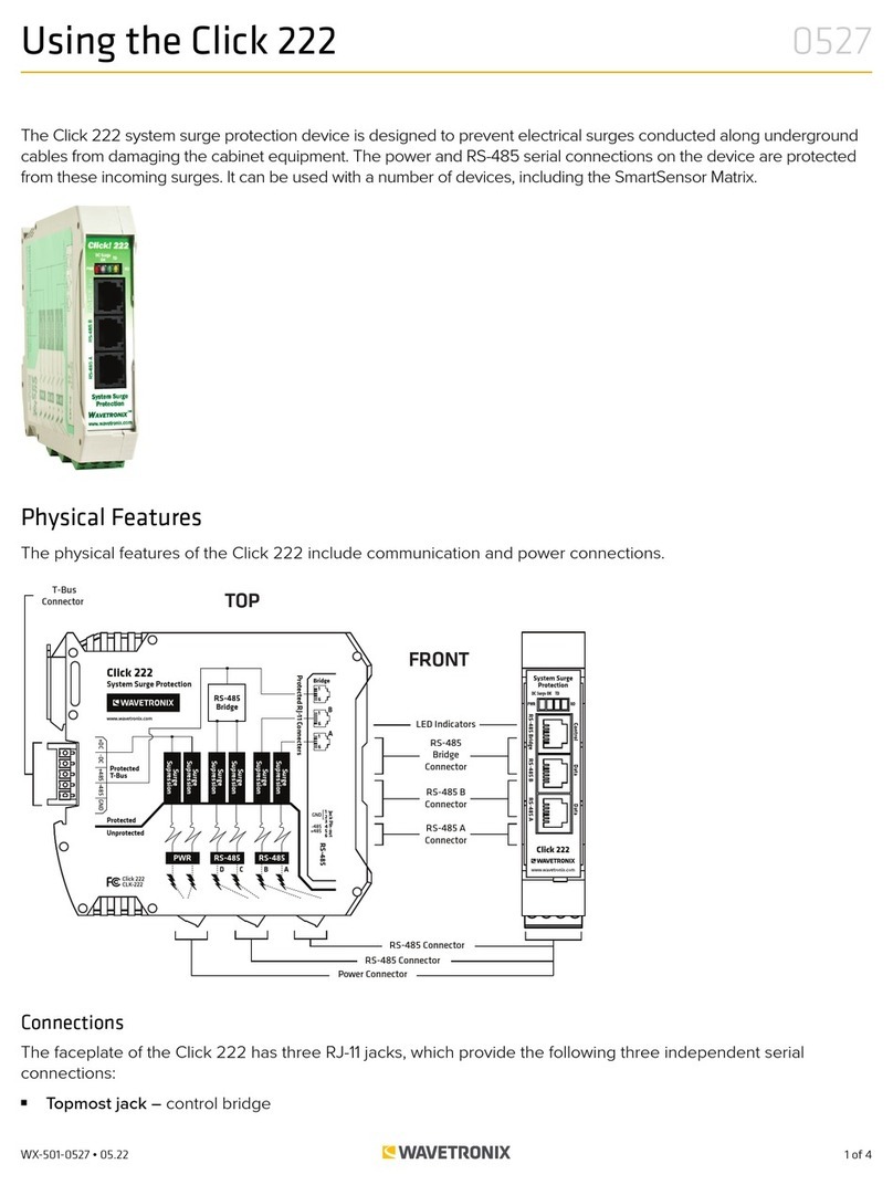
Wavetronix Click 222 User manual

Wavetronix

Wavetronix Click 222 User manual

Wavetronix Click 65 Series User manual

Wavetronix

Wavetronix Click 65 Series User manual

Wavetronix Click 65 Series Datasheet

Wavetronix

Wavetronix Click 65 Series Datasheet

Wavetronix Click 65 Series User manual

Wavetronix

Wavetronix Click 65 Series User manual

Popular Surge Protector manuals by other brands

Mersen STMT23-S Series installation instructions

Mersen

Mersen STMT23-S Series installation instructions

Vega B62-30W operating instructions

Vega

Vega B62-30W operating instructions

Furman PS-8RE III owner's manual

Furman

Furman PS-8RE III owner's manual

Transtector CB Series installation instructions

Transtector

Transtector CB Series installation instructions

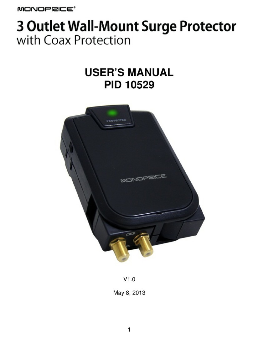
Monoprice PID 10529 user manual

Monoprice

Monoprice PID 10529 user manual

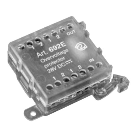
Vimar ELVOX 692E Installer's guide

Vimar

Vimar ELVOX 692E Installer's guide

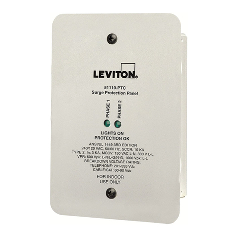
Leviton 51110-PTC installation instructions

Leviton

Leviton 51110-PTC installation instructions

Spectracom 8226 Installation guides

Spectracom

Spectracom 8226 Installation guides

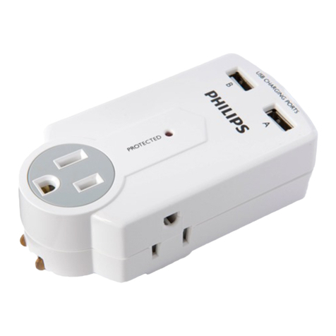
Philips SPP8038B/17 user manual

Philips

Philips SPP8038B/17 user manual

Radio Shack 61-2234 user manual

Radio Shack

Radio Shack 61-2234 user manual

Belkin PM01629 quick start guide

Belkin

Belkin PM01629 quick start guide

M-system MD7PM instruction manual

M-system

M-system MD7PM instruction manual

PSP Hurricane 4000 Series installation instructions

PSP

PSP Hurricane 4000 Series installation instructions

INFOSEC UPS SYSTEM S4 Black Line II user guide

INFOSEC UPS SYSTEM

INFOSEC UPS SYSTEM S4 Black Line II user guide

Liebert LM250120YARCE Technical specification

Liebert

Liebert LM250120YARCE Technical specification

PSP VB1-60-4XP Installation notes

PSP

PSP VB1-60-4XP Installation notes

Rocket Fish RF-HTS130 Quick setup guide

Rocket Fish

Rocket Fish RF-HTS130 Quick setup guide

Tripp Lite ISOBLOK2-0 owner's manual

Tripp Lite

Tripp Lite ISOBLOK2-0 owner's manual

manuals.online logo
manuals.online logoBrands
  • About & Mission
  • Contact us
  • Privacy Policy
  • Terms and Conditions

Copyright 2025 Manuals.Online. All Rights Reserved.