Auxiliary Battery Switch
UNCONTROLLED DOCUMENT
All information is provided by manufacturer
Updated 9/27/11
www.waytekwire.com
Phone I 800.328.2724 I 952.949.0765
Fax I800.858.0319 I 952.949.0965
Do not weld on the vehicle with the Auxiliary Battery Switch installed as damage to the product may result. If electric welding is
necessary, disconnect the cables attached to the T1 and T2 terminals. Damage due to electric welding while the unit is
installed will void InPower’s warranty.
Introduction
This manual provides instructions for installing the InPower Auxiliary Battery Switch (ABS). It is important that you follow these instructions
carefully and contact InPower if you need assistance or more information. You can reach InPower at:
InPower LLC
Customer Support
Tel: 740-548-0965
Toll Free: 866-548-0965
Web Site: www.InPowerDirect.com
Safety Precautions
This product requires the installer to be trained for installation and work on vehicle electrical systems. We recommend that all wiring meet the
SAE and applicable vehicle manufacturer’s wiring specifications. Inspect the product and all other components for damage before starting the
installation. Do not perform the installation if any problems exist.
Wear appropriate safety equipment such as eyeglasses, face shield and clothing when installing the equipment and handling the battery. Be
careful when working near a battery. Make sure the area is well ventilated and that there are no flames near the battery. Never lay objects on
the battery that can short the terminals together or to ground. If battery acid gets in your eyes immediately seek first aid. If acid gets on your
skin immediately wash it off with soap and water.
Mounting Location
• First determine where the module will be mounted.
• The ABS, although sealed, must be mounted in a protected and dry area.
• The ABS is not designed for exposure to saltwater spray, environmental debris or power washing.
• It must be mounted to a flat metal surface that maintains ambient temperature.
• The module must not be mounted in the engine compartment or any location near the
engine’s heat.
• Take into consideration the routing of the two battery cables.
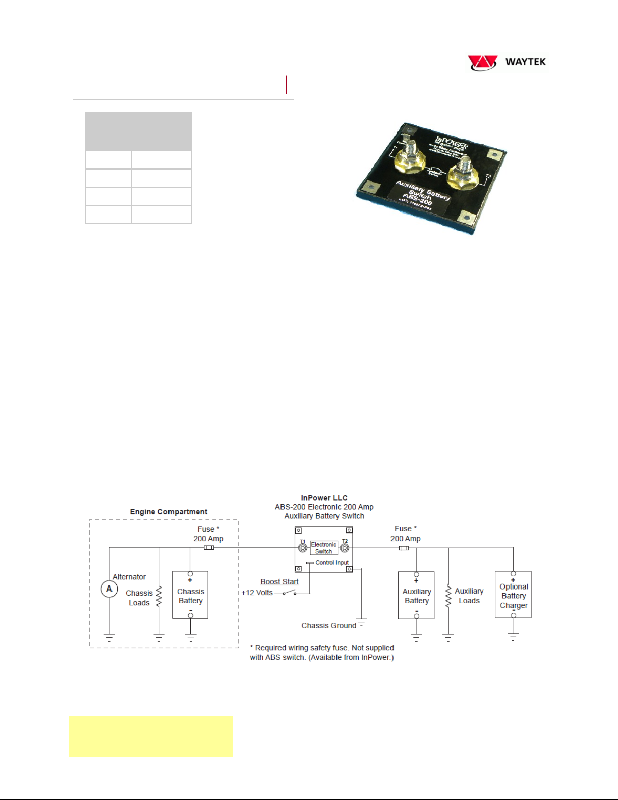
• Connect only the battery cables to the ABS power terminals. Do not use these terminals for a junc- tion post.
• For maximum thermal efficiency the mounting surface should be a thick metal surface such as an
aluminum plate 1/8 x 12 x 12 inches or larger.
• To facilitate heat transfer a square piece of thermal transfer material is supplied with each ABS. 1. Remove the clear plastic protective
coating and insert the heat transfer material between the module and the mounting surface.
2. Secure the module to the flat metal surface using four #6 or #8 screws and tighten to a torque setting of 5 inch pounds. Do not drill out
the contactor’s four mounting pad holes to use a larger bolt size. Drilling the mounting holes out will void the warranty.
Grounding
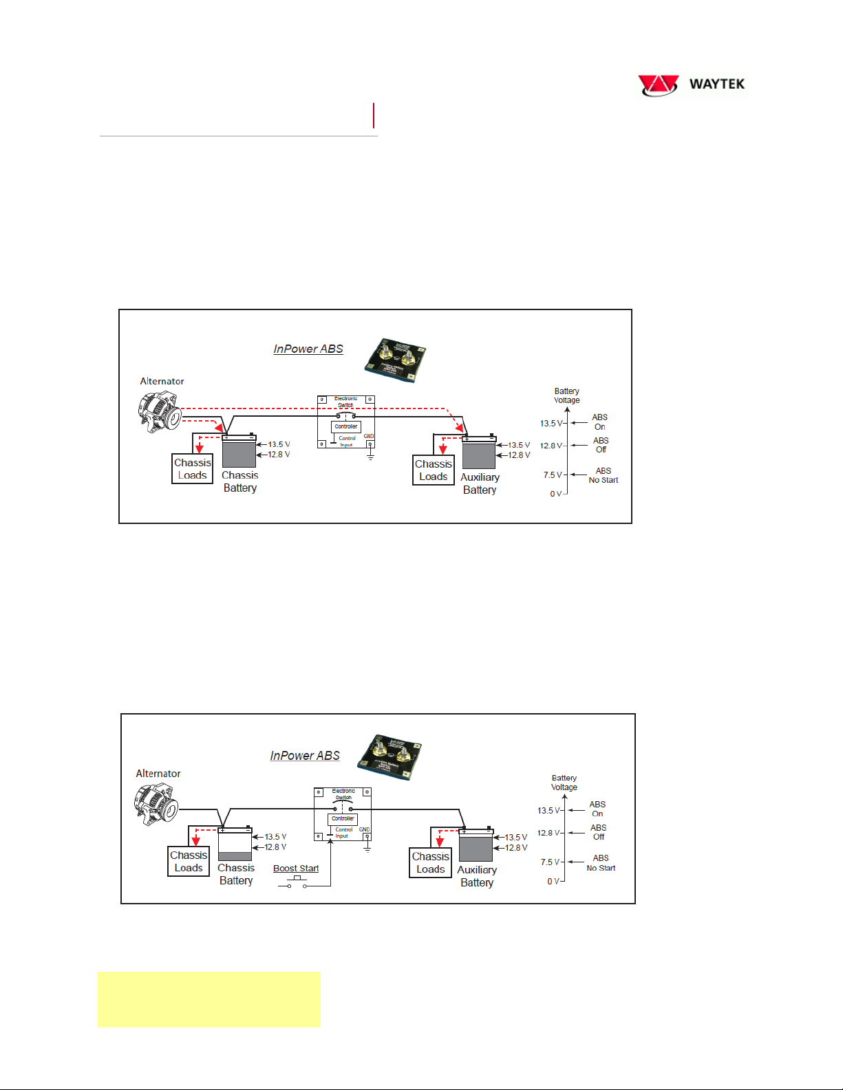
Proper operation of the ABS is dependent on a good quality ground system. Both the chassis battery and the auxiliary battery must be
connected to a solid common ground. The ABS must be connected to this common ground. Do not drill out the contactor’s four mounting
pad holes to use a larger bolt size. Drilling the mounting holes out will void the warranty. Install a #16 AWG ground wire with a ring
terminal under one of the four ABS mounting screws and connect it to the common battery ground. Note that the best ground is at the chassis
battery’s negative terminal.