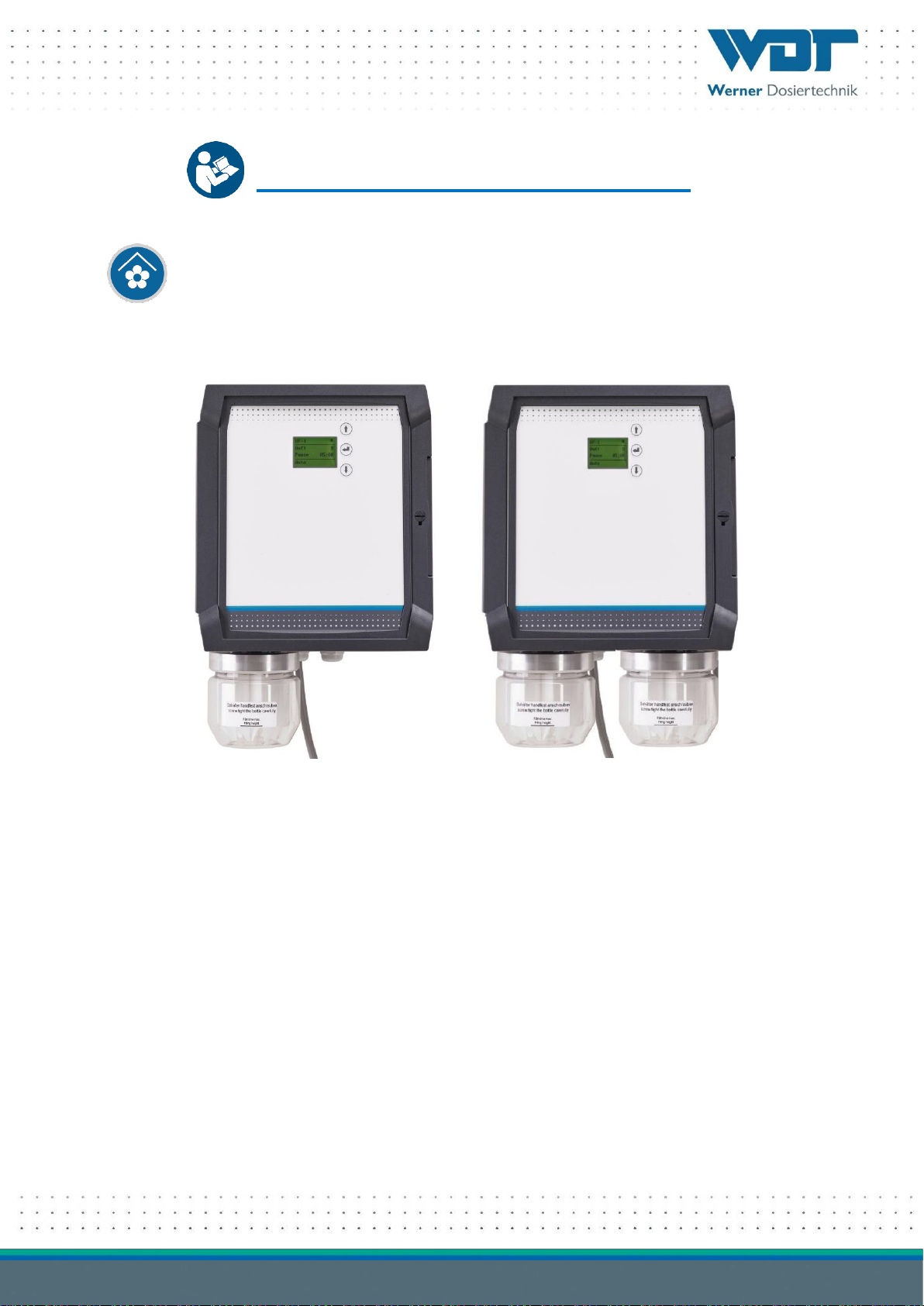
DUFTDOS-AK1 and AK2 dosing device
Index: 01 Date modified: 01/02/2023 OI No.: BA DW 039-01 DUFTDOS-AK1+2 NT35-R EN.docx Page 2 of 30
Table of contents
1 About these instructions / general .........................................................................................................4
1.1 Scope of applicability.................................................................................................................................4
1.2 Target group ..............................................................................................................................................4
1.3 Symbols used .............................................................................................................................................4
1.4 Warranty....................................................................................................................................................5
1.5 Further information ...................................................................................................................................5
2 Safety ......................................................................................................................................................6
2.1 Intended use ..............................................................................................................................................6
2.2 Safety notices.............................................................................................................................................6
2.2.1 Handling of chemicals, risks to humans and the environment..................................................................6
2.2.2 Protective measures and rules of conduct ................................................................................................6
3 Product description - scope of delivery ..................................................................................................7
3.1 Scope of delivery / accessories ..................................................................................................................7
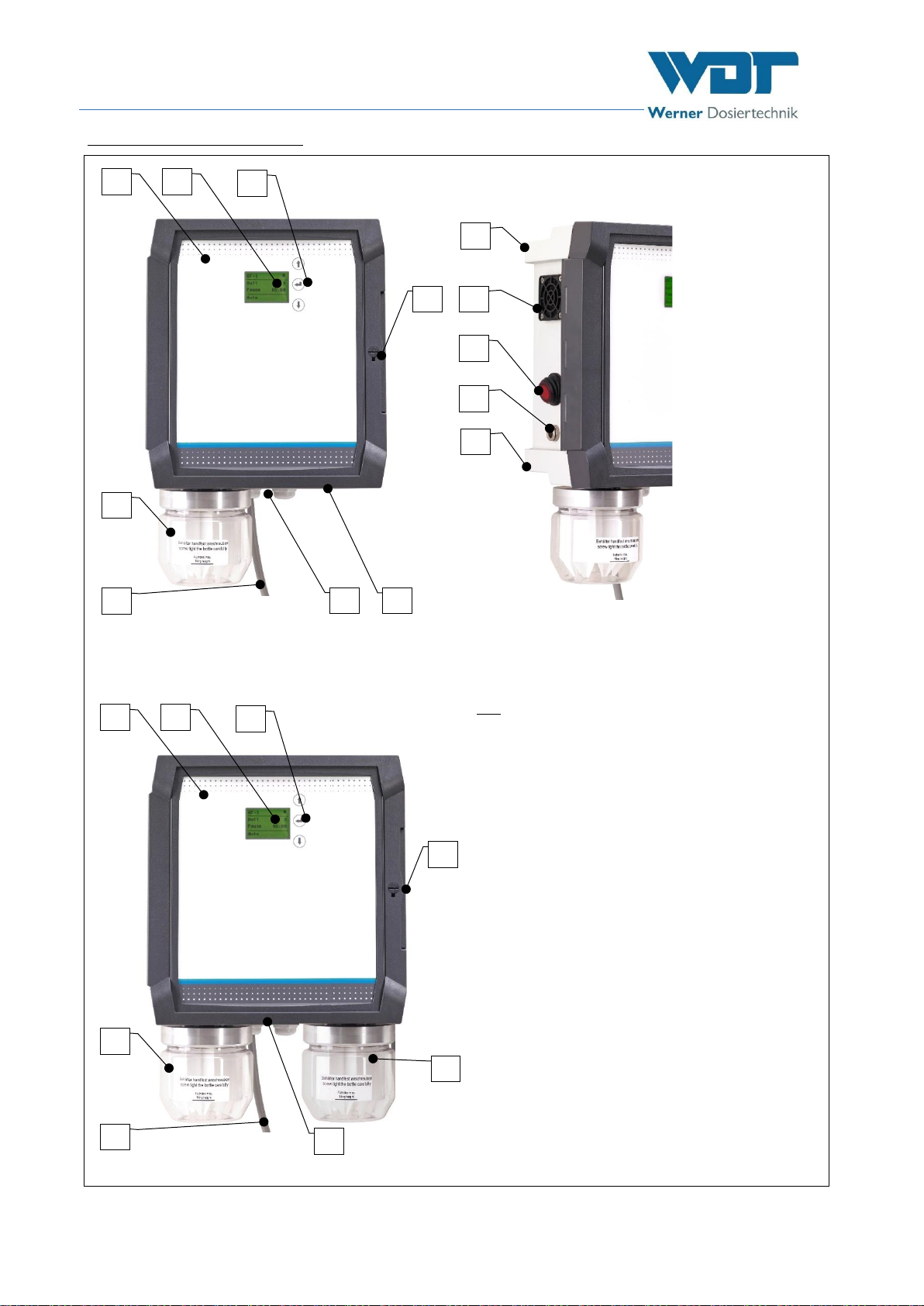
3.2 Product description....................................................................................................................................7
3.2.1 Control unit................................................................................................................................................9
3.2.2 Button plate (option) .................................................................................................................................9
3.2.3 Fragrance container...................................................................................................................................9
3.2.4 Inlet nozzle (standard) ...............................................................................................................................9
3.2.5 Inlet nozzle with heater (option) .............................................................................................................10
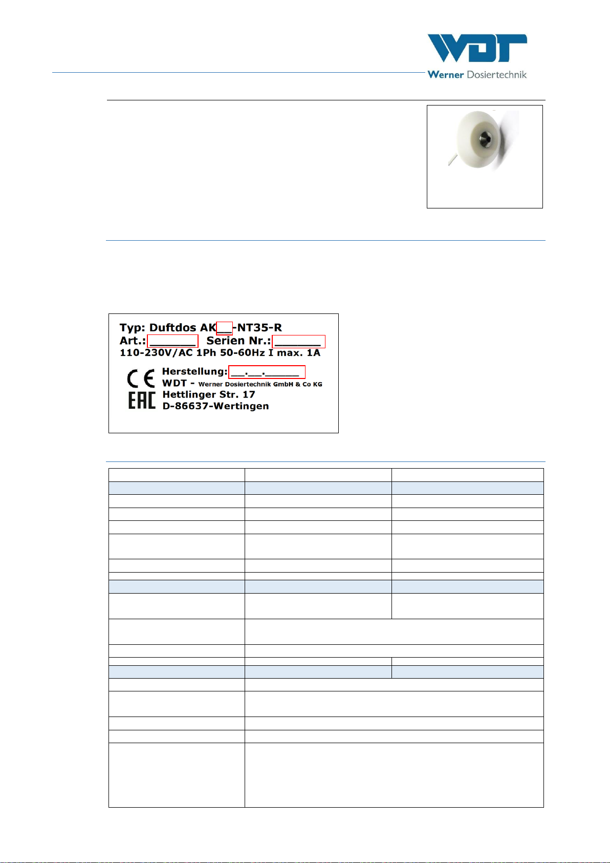
3.3 Device identification / identification plate ..............................................................................................10
3.4 Technical data..........................................................................................................................................10
3.5 Transport/storage....................................................................................................................................11
3.5.1 Storage of fragrance concentrate............................................................................................................11
4 Installation ............................................................................................................................................12
4.1 Select the installation site........................................................................................................................12
4.2 Installation instructions (suggested installation).....................................................................................12
4.3 Install control housing .............................................................................................................................13
4.3.1 Open/close the control housing ..............................................................................................................13
4.4 Install button plate (option).....................................................................................................................13
4.5 Install and connect the inlet nozzle .........................................................................................................14
4.6 Install and connect the inlet nozzle with heater......................................................................................14
4.7 Establish electrical connection ................................................................................................................14
5 Commissioning......................................................................................................................................15
5.1 Commissioning - remarks ........................................................................................................................15
5.2 Commissioning works ..............................................................................................................................15
5.2.1 Fill/replenish fragrance concentrate .......................................................................................................15
5.2.2 Establish power supply ............................................................................................................................15
6 Operation/service.................................................................................................................................16
6.1 General ....................................................................................................................................................16
6.2 Control unit - Software ............................................................................................................................16
6.2.1 Switch on DUFTDOS-AK / start query ......................................................................................................17
6.3 The operating menu ................................................................................................................................17
6.3.1 Operation modes .....................................................................................................................................18
6.3.2 Select the fragrance.................................................................................................................................18
6.3.3 Dosing time..............................................................................................................................................19
6.3.4 Pause time ...............................................................................................................................................19
6.3.5 Push button cycle (in push button operation mode)...............................................................................19
6.3.6 Test output ..............................................................................................................................................19
6.3.7 Test input.................................................................................................................................................20
6.3.8 Language..................................................................................................................................................20
6.3.9 Contrast ...................................................................................................................................................20
6.3.10 Info...........................................................................................................................................................20
6.3.11 Data log....................................................................................................................................................20
6.3.12 Factory reset ............................................................................................................................................20
6.3.13 Config / password protection / push button ...........................................................................................21
6.4 Button plate function...............................................................................................................................21