5
http://support.weathermatic.com
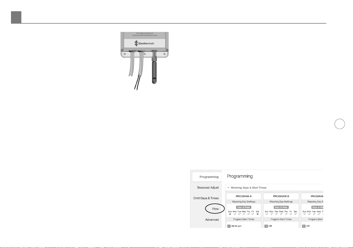
6. Connect the Aircard to the Flow
Sensor cable. Take the cable
leaving the bottom of the Aircard
next to the Antenna and connect
it's wires to the Flow Sensor
cable. Polarity is important!
Connect the red to red and black
to black.
Note: The wire connection
between the Aircard and the SLFSI Flow Sensor should
be made inside the housing of the SmartLine controller,
or an enclosure. Only use the provided 3M® Scotchlok™
Connectors. Insert the unstripped wires into the holes
of the connector. Use a pair of pliers to make the
connection by driving the cap down flush with the top
edge of the connector body. Verify wires are secure.
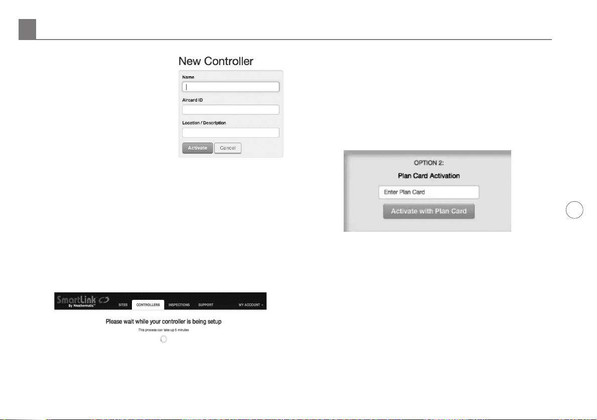
7. If you have not already activated the SmartLink Flow
Aircard, then proceed to Steps 1 and 2.
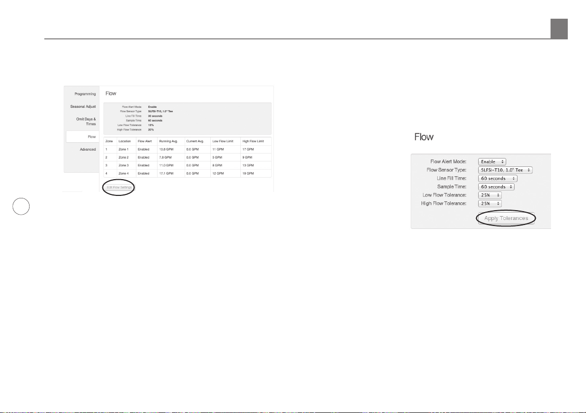
4.0 SmartLink Network Global Flow Settings, Zone
Flow Settings, and Operation.
SmartLink Flow Aircard, in conjunction with SmartLink
Flow Sensor, will shut down zones that report flow usage
outside of the user defined high/low tolerance range. The
entire system will be shut down if it detects two zones in a
row reporting flow usage outside of the user defined high/
low tolerance range. This indicates a system mainline break
has occurred. With a Master Valve installed, breaks in the
system’s mainline will be protected, because the Master
Valve is turned off when the alert occurs. Systems without
a Master Valve installed will still register the alerts and shut
down program operation, but with no Master Valve to shut
down, the break can't be isolated.
Initial Programming or Changing of Settings in SmartLink:
Note: SmartLink Flow Aircard will operate with the attached
SmartLine controller in either Smart “Auto Adjust” or Basic
“Standard” Mode.
1. The online setup and operation of the Flow Sensor
requires you to be logged in to your SmartLink Network
account. Once logged in, view the controller where you
installed the SmartLink Flow Aircard, as explained in
Section 2.
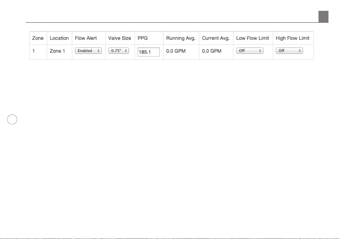
2. The first page that appears is the main landing page
for your controller. On the left side of the page (scroll
down), locate the Flow tab to reveal the Flow Settings.
SmartLink Network Global Flow Settings, Zone Flow Settings and Operation 4.0
Red Black