Weathermatic SLFSI-T10 Guide

1 | P a g e
Two-Wire System Design Guide
Welcome to the Weathermatic Two-Wire System Design Guide. This guide has been developed
to provide an overview and detailed notes and tips for contractors and specifiers who are working with
Weathermatic Two-Wire systems.
This guide includes the information necessary to specify a Weathermatic Two-Wire systems. Written
specifications in CSI and Microsoft Word format as well as CAD details reference herein are available on
the Weathermatic website at www.weathermatic.com
INTRODUCTION
Two-wire decoder technology has been around the irrigation industry for more than three decades
beginning in the golf industry (primarily in Europe) in the mid 1980’s as a cost effective method for
wiring irrigation valve-in-head rotors used extensively in golf irrigation systems. The cost savings was a
result of eliminating thousands of feet of copper wire used to control valves. Two-wire systems also
made it far easier to trace and connect wire from the irrigation controller to the sprinkler head without
having to use specialized tone equipment and multiple installers.
By the late 1990’s, manufacturers began to bring two-wire technology to the U.S. Early systems
primarily used DC current, which is highly susceptible to faults in wiring, which led to a number of
system failures as contractors had to learn to be diligent with wiring. Additionally, DC latching solenoids,
which are highly susceptible to “sticking” open, were required to be used on each irrigation valve.
Fortunately, irrigation manufacturers figured out how to convert the two-wire DC signal to AC thus
eliminating the valve failure problem.
Today, two-wire irrigation system are a high majority of the types of new irrigation systems being
installed in the U.S. especially in the Central and Eastern U.S.
WHAT IS A TWO-WIRE IRRIGATION SYSTEM?
In a two-wire decoder system, a single pair (thus the name “two-wire”) of poly insulated wires is run to
all valve locations on a “wire path”. At each irrigation valve location, a valve “decoder”is wired to each
valve. Each decoder has a programmable address (typically the zone number), which identifies it to the
two-wire decoder irrigation controller. The two-wire cable is connected to all these decoders on the
wire path.
During operation, the controller broadcasts an “ON” command to activate a specific address. All of the
decoders wired on the same two-wire path “decode” the message, but only the appropriate decoder
responds and turns the attached valve on. The decoder also reports back to the controller that it
received the command and has responded. The lack of response or an electrical issue will trigger an
error code on the controller to aid in troubleshooting. When the irrigation cycle is finished, the
controller stops sending the “ON” command and decoder responds by turning the valve off.
Electrically a two-wire controller actually sends the “ON” command hundreds of times per second thus
enabling the system to communicate to multiple decoders at the same time over the same wire path

2 | P a g e
over long distances. Operating this way provides the benefit of longer wire runs, lower power
consumption and increased lifespan controller and valves.
BENEFITS OF A TWO-WIRE SYSTEM
•Less Labor to Install - Two-wire path installation is easier to install and connect to controller and
valves saving labor. With only a single cable with two conductors, the installation requires
smaller trench space and enables the contractor to quickly lay the wire in the ground without
concern for routing the cable to the proper valves or later trying to
identify station wires.
•Easier and Faster to Troubleshoot –When conventionally wired
controller wires are accidentally dug up or trenched through a repair
would require several hours. A two-wire cable, on the other hand,
would be an easy repair. The contractor simply has to splice the black
wire to black and red to red to successfully make the repair. Also when
a group of zones fail to operate, troubleshooting is made easier by
identifying the part of the wire path that does not work and finding the
splice or wire defect that is the cause of the problem. On a

3 | P a g e
conventionally wired system, a single valve failure can take hours to troubleshoot because the
technician must trace the entire length of the wire to find the defect.
•Less Wire Means Fewer Problems - Exposure to shovels, rodents, and even lightning is
minimized with two-wire paths because there is less wire in the ground.
•Extend System in Phases - Irrigation systems can be easily expanded or subdivided after the
original installation without running spare wires, or retrofitting new wiring back to the
controller. On a two-wire system expansion can take place by simply spicing into the end of a
two-wire path and continuing the wire to the new phase of a project.
•Decoders can be positioned anywhere along the two-wire path –Positioning, adding or moving
decoders and valves is easy because they can be positioned anywhere along the two-wire path
during construction or after.
•Better Water Management –Adding, splitting, or moving zones makes it easier to hydrozone
plant material and/or modify planting plans in the field after the original design is completed.
•Reduced Electrical Cost –Two-wire systems are more efficient at power consumption. Because a
two-wire controller actuates the valve hundreds of times a second, the decoder doesn’t actually
operate for the full run time thus consuming less electricity. This is especially important for solar
two-wire systems where power consumption is a critical issue.
•Valves Last Longer –The cyclical nature of two-wire power use to the valve leads to longer valve
lifespan. Because a two-wire controller actuates the valve hundreds of times a second, the
solenoid on the valve doesn’t actually operate for the full run time thus extending the life of the
solenoid.
•Resists Lightning –Since a two-wire system has less wire in the ground, it tends to be less
susceptible to lightning damage vs a conventionally wired system if the decoders are installed in
protected clusters. Proper grounding and wire splicing is critical to ensuring a two-wire system is
more resistant to the effects of lightning.
•Two Wire Decoder Systems can be Less Expensive than Conventional Wire Systems –Larger
station count two-wire systems are less impacted by high wire costs than conventional systems.
The primary driver in this is the cost of copper and its influence on irrigation wire prices.
EXAMPLE
Conventional Systems
Two-Wire Systems
48 station controller
$660
$590
1 1/2” Valve
$3,240
$3,240
Decoder
N/A
$3,619
Wire
$6,774
$1,166
TOTAL
$10,672
$8,614

4 | P a g e
WEATHERMATIC SMARTWIRE™ TWO-WIRE DESIGN
Two-Wire Layout………………………………….
Page 4
Weathermatic Decoders……………………….
Page 13
Wire Sizing…………..……………………………….
Page 5
Decoder Programming………………………….
Page 14
Type of Two-Wire…..…………………………….
Page 5
Decoder Errors………………………………………
Page 14
Surge Arrestor…………..………………………….
Page 5
Master Valves……………………………………….
Page 15
Wire Splice..………………………………………….
Page 6
Flow Sensors…………………………………………
Page 16
Grounding…………..………………………………..
Page 8
Warranty……………………………………………….
Page 17
Grounding Grid.……………………………………
Page 10
Weathermatic Solar………………………………
Page 18
Weathermatic SmartWire Controllers…..
Page 12
Weathermatic SmartLink………………………
Page 18
Weather Station / Rain-Freeze Sensor….
Page 12
Specification Checklist…………………………..
Page 20
TWO-WIRE PATH LAYOUT
Two-wire controllers typically have connections for multiple wire paths enabling the system to power
decoders running in multiple directions. The Weathermatic SmartWire™ two-wire controllers have 3
separate wire path connections. These are labeled 1, 2, & 3 for wire path #1, wire path #2 and wire path
#3 respectively.
Although wire paths can be designed to run in multiple directions, attention should be given to the
limitations on distance that each wire can be installed.
The Weathermatic SmartWire™ system allows you to have several options in cable routing to determine
the most efficient two-wire layout for your project. Maximum decoder to valve distance is 100 feet
(30.5m).
Each two-wire run can be laid out in Straight Run, Complete Loop, Star, or Combination configurations
as shown below.
Last Decoder STAR
CONFIGURATION
Last Decoder
Last Decoder
Last Decoder
Last Decoder
LOOP
CONFIGURATION
SmartWire
Controller
SmartWire
Controller

5 | P a g e
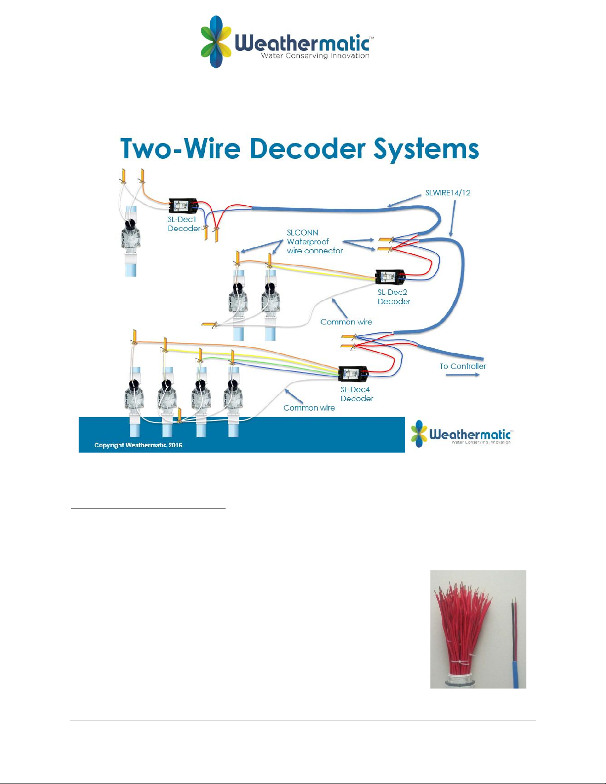
It is suggested that a continuous loop be laid out around the site. This usually follows the main water
lines. The loop will start at the SmartLine® controller and continue around the site and then return to
the controller. This provides the best communication and power path for the system. The loop provides
a redundant path for the power and signal allowing the system to continue operation if the loop is cut.
Branches can come off the main loop and they do not need to be looped back to the main trunk line.
These branches can be other loops, stars or single dead-end lines. The system will work with most wiring
configurations if the wire length requirements are met.
WIRE SIZES
The configuration and size of the wire conductor used will determine the maximum length a wire path
can run. The chart below summaries these distances:
Star Configuration - Wire distance to the furthest decoder, no loop:
Wire Size (Gauge) #18 #16 #14 #12
Wire Length (feet) 1,000 2,000 4,000 6,000
Loop Configuration - Wire distance to the furthest decoder in the loop:
Wire Size (Gauge) #18 #16 #14 #12
Wire Length (feet) 2,000 4,000 10,000 10,000
NOTE: Maximum total wire path length is 10,000 feet
TWO-WIRE
Weathermatic recommends the use of Weathermatic SLWIRE12 or SLWIRE14 cable specifically designed
for an irrigation control system and complying with the following specifications:
•Conductors must be soft drawn, annealed, solid copper conforming to ASTM 33
•Conductor insulation must be 4/64-inch thick polyvinyl chloride (PVC) conforming to UL #493
•The two insulated conductors laid in parallel and encased in a single outer jacket of 3/64-inch thick,
high-density, sunlight resistant polyethylene conforming to ICEA S-61-402 and NEMA WC5, having a
minimum wall thickness of .045-inch
•The two conductors must be color-coded: normally one conductor red and the other black. Both
conductors shall be the same size.
HOW TO SPECIFY:
Weathermatic SmartWire™ Wire
SLWIRE-122 –12 gauge, 2 conductors with poly outer jacket, available in 1,000 or 2,500 feet rolls, blue
outer jacket is standard (other outer jacket color options are availble as special order but can be
expensive)
SLWIRE-142 –14 gauge, 2 conductors with poly outer jacket, available in 1,000 or 2,500 feet rolls, blue
outer jacket is standard (other outer jacket color options are availble as special order but can be
expensive)
WEATHERMATIC SMARTWIRE™ SURGE ARRESTOR
Weathermatic SLGDT gas discharge tube lightning arrestors must be used on all two-wire grids. The
SLGDT lightning arrestor attaches directly to the two-wire system and helps dissipate static electricity
generated by a nearby lightning strike. While Weathermatic components have lightning arresting
features, the SLGDT provides an extra measure of protection.

6 | P a g e
Features:
•Conductors must be soft drawn, annealed, solid copper conforming to ASTM 33
•Conductor insulation must be 4/64-inch thick polyvinyl chloride (PVC) conforming to UL #493
•Protects the two-wire system from excessive static charges created by a lightning strike.
•Sealed and impervious to moisture, salts, fertilizers and mild chemicals.
•Shock resistant.
•Freeze/heat resistant (-20° to 60° C).
•No electrical contact with the soil.
•Each Lightning Arrestor protects a 300-foot radius.
Electrical Specifications
•Requires no power from the two-wire system
•Can only be connected to SmartWire™ two-wire systems
HOW TO SPECIFY:
Weathermatic SmartWire™ Surge Arrestor
SLGDT –Surge Arrestor (install every 600 feet). Use SLGDT at beginning and end of each wire run (if
greater than 50 feet) and at a maximum of 600 foot intervals. See below.
WEATHERMATIC SMARTWIRE™ WIRE SPLICE
The wire splice is the most important part of any two-wire system. The majority of issues seen in two-
wire systems is primarily due to bad wire splices. The following issues can be a result of bad wire splices
on any two-wire system:
•Valves fail to turn on
•Decoder not found error codes at the controller
•System works initially but fails after water infiltrates a bad splice
•Some valves turn on normally while other valves fail to turn on.
•Controller shows an over current alert
Most of these issues can be avoided if splices are installed correctly.
SmartWire
Controller
SLGDT
SLGDT
SLGDT
SLGDT
600 feet max 600 feet max
50 feet max
600 feet max
SLGDT

7 | P a g e
The correct type of splice kit which should be used includes an electrical spring connector (commonly
called a “wire nut” and a high impact, UV-resistant polypropylene tube prefilled with moisture-resistant
gel. If installed correctly the two-wire splice kit will be waterproof.
HOW TO SPECIFY:
Weathermatic SmartWire™ Splice Kit
SLCONN –Waterproof wire connector for 2 wires connections
Note –(2) SL-CONN kits are included in each Weathermatic SmartWire™ Decoder
Proper Splice (see diagram below)
1. Strip wires ½”
2. Twist stripped wire clockwise with lineman’s pliers. Apply the electrical connector and twist in a
clockwise direction.
3. Insert the splice into the gel-filled insulator tube. Push past the locking fingers to hold the
connector in place. Bottom it out.
4. Position wire channels and snap insulator tube cover closed.
5. Pull on wires to ensure waterproof connection.
Note: Keep BLACK to BLACK and RED to RED when wiring two-wire connections.
Splice issues usually arise from any of the following:
•Electrical connector not fully twisted on to wires. This causes an open wire condition
•Splice not full inserted into insulator tube. This allows water to infiltrate into the splice causing a
wire short. Usually this issue doesn’t show up until a few months after installation.
•Insulator cap not closed. This also allows water to infiltrate into the splice causing a wire short.
Usually this issue doesn’t show up until a few months after installation.
It is a good practice to test a few splices during jobsite inspection by taking a couple random splices
apart to inspect for the issues mentioned above. The contractor will have to re-splice the connection
with a new splice kit* but this practice ensures the installer has likely installed the remaining wire splices
correctly. If the random sample of splices are not correct, it is highly likely the remaining splices were
also installed incorrectly and the system will fail.
*Note: Wire splice kits CANNOT be reused.
SL-CONN

8 | P a g e
WEATHERMATIC SMARTWIRE™ GROUNDING REQUIREMENTS
Grounding all electrical connections of a two-wire system is a critical step to ensure the system is
protected from damage by electrical surges and nearby lighting strikes. Although every irrigation
controller (conventional wired or two-wire) should be grounded, this step is often overlooked during the
installation. System failures and even a fire can be easily avoided by following a few simple steps.
Lightning, in particular can do a lot of damage to an irrigation system because irrigation systems have a
lot of wires underground where lightning can access the entire valves and wire network. Although
grounding can prevent a lot of electrical damage to an irrigation system, a direct hit from lightning will
likely cause damage even if the system is properly grounded.
The critical measurement for determining whether a system is grounded properly is call “resistance-to-
ground” In other words, it is the measurement of how easily a surge of electricity or lightning can enter
to the earth once it is made its way on to an irrigation systems electrical circuits. The lower this
measurement is, the better. Typically, if the resistance to ground is lower than the resistance of an
irrigation systems electrical components, the electrical surge will find its way to earth and not through
the electrical components. This is called least path of resistance.
The objective of proper grounding techniques is to provide the least path of resistance for any potential
electrical surge or lightning strike.
The green wire on any irrigation equipment is the wire that needs to be connected directly to the
grounding circuit. For Weathermatic SmartWire™equipment, any GREEN ground wire must be attached
to a #8* solid bare copper wire using the SLCONN splice kit. The bare ground wire must be connected to
a grounding circuit with 12 Ohms or less resistance to earth ground, measured with a ground resistance
meter or Megger. (see below)
*Ground wire must be one size larger than the largest wire in the system.
A grounding circuit is comprised of 4 major components:
•Ground Rod(s) and/or Plate(s).
•Ground Conductor - #8 bare copper wire
•Exothermic or Cadmium Weld connections.
•Soil and/or Ground Enhancement Materials.
Megger
Ground
resistance
clamp meter
8-foot bare copper
ground rod
Copper
ground plate
Cadmium weld
connector
Soil
enhancement
material

9 | P a g e
Ground Rods/Plates must be installed 6” below grade or below frost line, located within an irrigated
zone to maintain soil moisture and maximum ground performance. All connections must be made in a
minimum 6” min. valve box. Rods are installed perpendicular to the ground while plates are installed
horizontal to the ground. See manufacturers recommendation for correct installation.
Ground Rods shall be UL listed “copper clad”, 5/8” minimum diameter, 8’ of length, and must meet the
requirements of NEC article 250-52(c).
Ground Plates shall be a copper alloy specifically intended for grounding, with a minimum thickness of
0.060”. Each plate shall expose a minimum of 5 square feet of surface area to contact the soil, and meet
the requirements of NEC article 250-52(d).
Grounding Conductor shall be a solid, bare copper wire or strap used to connect the green ground wire
to the ground rod or plate, sized appropriately to achieve specified resistance.
NOTE: The bare copper wire should run perpendicular to the two-wire path
Exothermic or Cadmium Weld products such as CADWELD One Shot ®, shall be used to connect the #8
AWG bare copper ground conductor to the ground rod or plate.
Ground Enhancement Materials such as Powerset®, PowerFill®, and GEM® shall be used as required to
achieve specified resistance to earth ground.
Local soil and site conditions will dictate what extent of grounding measures will be required. Generally
there are 3 soil types that each require different methods and equipment to achieve the 12 Ohm
minimum resistance to ground:
•Clay soils: A single ground rod is typically sufficient, located in an irrigated zone, with CADWELD
connections and no soil amendments. Some sites require a 6” diameter hole to be augured and
backfilled with Ground Enhancement Materials.
•Loam Soils: Typically a 3-ground rod grid is required, located in an irrigated zone, with CADWELD
connections, 6” augured holes and Ground Enhancement Material as required.
•Sandy soils: Require the most extensive ground circuits which require combinations of ground rods,
plates, CADWELD connections and ground enhancement materials, located in an irrigated zone.
Any combination of the above recommendations should be considered to achieve 12 Ohms or less.
Long-term maintenance of any ground system requires that it be located within an irrigated or wetted
zone.
NOTE - DO NOT USE single screw ground clamps as these clamps will loosen
over time.
Weathermatic recommends the use Exothermic or Cadmium Weld connections for all
ground rod and plate connections. See https://youtu.be/T5DoB26TFtI for video of how this
is done.
Single screw
ground clamp
Cadweld One Shot

10 | P a g e
HOW TO SPECIFY:
Weathermatic SmartWire™ Grounding
•Use #8 bare copper wire
•Maximum 12 Ohms resistance to earth ground
-Test with 3-point Megger or ground resistance clamp-on meter
•Use Exothermic or Cadmium Weld for all ground connections
•Use grounding enhancement material (GEM) to decrease resistance to ground
Specification Example:
Contractor shall test each grounding grid at completion of project to comply with 12 Ohms or less
electrical requirement. Contractor shall rectify and ground grids that test above this requirement prior to
project completion.
Weathermatic Recommended Grounding Grid Configurations
•3-rod grid
•1-rod & 1-plate grid
•2-plate grid
Grounding –3-rod grid
•8-foot ground rod triangle grid
SLGDT
SLWIRE
14/12
8’ copper
clad
ground rod
SLCONN
Cadweld
#8
bare
copper
wire
6” valve
box
First Rod Connections
SLWIRE14/12
Minimum 8 feet
Cadweld
#8 bare
copper wire
3-Rod Ground Grid Configuration
Perpendicular to
wire path
Two-wire Path
Grounding

11 | P a g e
Grounding –Rod & Plate Configuration
Grounding –2-Plate Configuration
SLWIRE14/12
Minimum
11 feet
#8 bare
copper wire
8-foot
ground rod
8-foot x 4-inch
ground plate
SLWIRE14/12
Minimum 3
feet
#8 bare
copper
wire
8-foot x 4-inch
ground plate

12 | P a g e
WEATHERMATIC SMARTWIRE™ CONTROLLERS
The Weathermatic SL9600TW is pre-configured for large two-wire installations.
The SL9600TW is available to operate up to 48 decoders (SL9648TW) or up to 96 decoders (SL9696TW)
HOW TO SPECIFY:
Weathermatic SmartLine Two-Wire Controller
For up to 48 decoders/stations:
SL9648TW –SmartLine Controller. Up to 48 decoder addresses
For up to 96 decoders/stations:
SL9696TW –SmartLine Controller. Up to 96 decoder addresses
WEATHERMATIC WEATHER STATION
The SLW weather station can be added to any SmartLine Two-Wire Controller to enable ET to be used
for weather adjusted run times. SLW is available in a wired (SLW1) and a wireless (SLW5) version. In
addition, the SLW weather station incorporates a rain sensor to shut down for rain settable at ¼” - ½”
and a freeze sensor which will interrupt irrigation when the temperature drops below 37°F.
HOW TO SPECIFY:
Weathermatic SmartLine Weather Station
SLW1 –Wired Weather Station
OR
SLW5 –Wireless Weather Station*
*Note: The SLW5 wireless weather station can be located up to 1,500 from the SmartLine controller.
WEATHERMATIC SMARTWIRE™ RAIN/FREEZE SENSOR
The RFS rain/freeze sensor can be added to any ProLine Two-Wire Controller to incorporates a rain
sensor to shut down for rain settable at ¼” - ½” and a freeze sensor which will interrupt irrigation when
the temperature drops below 37°F degrees. The RFS is available in a wired (RFS1) and a wireless (RFS5)
version.
HOW TO SPECIFY:
Weathermatic ProLine Rain/Freeze Sensor
RFS1 –Wired Rain/Freeze Sensor
OR
RFS5 –Wireless Rain/Freeze Sensor*

13 | P a g e
*Note: The RFS5 wireless weather station can be located up to 1,500 from the ProLine controller.
WEATHERMATIC SMARTWIRE™ DECODERS
A decoder is installed at each valve box to activate the valves. Each decoder has a unique address which
identifies it to the Weathermatic SmartWire™ Controllers. The SmartWire™ controller broadcasts a
command to activate on a certain address. All the decoders on the two-wire system “decode” the
message but only the appropriate decoder responds and turns the attached valve on or off. The decoder
responds back to the decoder module with a status message.
Weathermatic SmartWire™ Decoders are available in 1, 2, or 4 address configurations. Valves that are
grouped to together can use a 2 or 4 address decoder to reduce the number of decoders needed for a
system.
Each decoder will have RED and BLACK wires. These are the wires that will connect to the two-wire path.
The RED and BLACK are also the wires that you will insert in the Programming Ports on the
Weathermatic SmartWire™ Controllers to program the decoder.
The wires on the other end of each decoder are for connection to the valves. A white wire on the
decoder is used for the common to all valves connected to the decoder.
HOW TO SPECIFY:
Weathermatic SmartWire™ Two-Wire Decoders
SL-DEC1 –Single Address Decoder
SL-DEC2 –Two Address Decoder
SL-DEC4 –Four Address Decoder
While Weathermatic SmartWire™ Two-Wire Decoders have lightning arresting features built into each
unit, Weathermatic strongly recommends the installation the SLGDT surge arrestor. The SLGDT provides
an extra measure of lightning protection. The SLGDT lightning arrestor attaches directly to the two-wire
system and helps dissipate static electricity generated by a nearby lightning strike.
WEATHERMATIC DECODER COMPATIBILITY
Weathermatic SmartWire™ Two-Wire Decoders are only compatible with the Weathermatic
SmartWire™ Controllers. Each manufacturer uses proprietary programming to program their respective
decoders therefore each manufacturer’s decoders are not compatible with any other manufacturer. For
retrofitting a decoder project with Weathermatic SmartWire™, the existing decoders MUST be changed
out to Weathermatic SmartWire™ Two-Wire Decoders.

14 | P a g e
Programming each decoder’s address is easy using the Weathermatic SmartWire™ Decoder Module
Weathermatic SmartWire™ Decoder Module Programming Steps
1. Select the PGM mode
2. Insert the RED and BLACK wires into the Programming Ports
3. Use up/down arrow buttons to select the zone number.
4. Push Program Zone button
5. A GREEN status light will confirm your selection.
6. Mark the zone number programmed on the decoder.
DECODER SYSTEM ERROR CODES
If a decoder cannot be located or a short, open or over current or over temperature is sensed by the
Weathermatic SmartWire™ Decoder Module, it will cause a FAULT message to appear on the display of
the SmartLine® controller. Open the SmartLine® panel and check the FAULT on the display of the
Weathermatic SmartWire™ Decoder Module. After the FAULT is repaired, press the Program Zone
button on the Weathermatic SmartWire™ Decoder Module to clear the error message. Refer to the
table below for Weathermatic SmartWire™ Decoder Module error messages.
Zone number
up/down Top light = program
mode
Bottom light = run mode
Switches between
program and run
modes
Program selected
zone number to
connected decoder/
clear errors
Program status light
Green = success
Red = error
Decoder
Programming
Ports
2-wire path terminals
R=Red, B=Black
Power from
“Hot” post
Master
valve

15 | P a g e
Error Codes –Errors will be displayed in screen
Fault Code
Description
E1
No decoder found
E2
Two-wire over current
E3
Open circuit at solenoid
E4
Short Circuit at solenoid
E5
Decoder Communication Error
E6
High Temperature Shut Down
E7
Decoder Programming Failure
MASTER VALVE(S)
If you are using a master valve or pump start relay, must connect the master valve or pump start relay to
a SLDEC1 decoder. You will also need to program a decoder as (Zone 97 and 98 for SL9600TW –the
SL9600TW can operate 2 master valves) for use with the pump start relay or master valve.
HOW TO SPECIFY:
Master Valve
8200CR-010 –1” 8200 Brass Commercial Dirty-Water Master Valve
8200CR-012 –1 ¼” 8200 Brass Commercial Dirty-Water Master Valve
8200CR-015 –1 ½” 8200 Brass Commercial Dirty-Water Master Valve
8200CR-020 –2” 8200 Brass Commercial Dirty-Water Master Valve
8200CR-025 –2 ½” 8200 Brass Commercial Dirty-Water Master Valve
8200CR-030 –3” 8200 Brass Commercial Dirty-Water Master Valve
MAX-DW-10 –1” MAX Commercial Dirty-Water Master Valve
MAX-DW-15 –1 ½” MAX Commercial Dirty-Water Master Valve
MAX-DW-20 –2” MAX Commercial Dirty-Water Master Valve
SB-10F –1” Silver Bullet Light Commercial Dirty-Water Master Valve
SB-15 –1 ½” Silver Bullet Light Commercial Dirty-Water Master Valve
SB-20 –2” Silver Bullet Light Commercial Dirty-Water Master Valve
NOTE: Wired to decoder - Master valve must be wired directly to its own decoder. Be sure to program it
as zone 97 or 98 in SL9600TW using a 1-valve decoder

16 | P a g e
FLOW SENSOR
The Weathermatic SmartWire™ Controller can utilize a flow sensor provided the controller is connected
to a SmartLink Aircard. Due to the need for accuracy in the flow measurement, flow sensors must be
wired back to the Aircard using a double-jacketed, shielded, twisted pair, direct bury PE type cable
FLOW SENSOR SIZING
Flow sensors should be sized to accommodate the range of flows they will measure, rather than match
the size of the pipeline. Generally accepted design practices recommend that the maximum velocity of
water in PVC piping systems does not exceed velocities of 5 feet per second (f/s). Keeping the velocity
below this level helps minimize the effects of water hammer and protects the pipe. In addition, pipe size
may be oversized to reduce pressure drop caused by friction losses.
Irrigation systems don’t operate at a fixed flow rates; there are always variations in the size of flow
zones or differences in the types of sprinkler heads or emitters used. Often times the velocity in the
pipeline is far less than the maximum flow and can be so low that it can’t be detected. No flow sensor
can measure down to zero flow. There is always a minimum flow rate or velocity below which there is
not enough energy in the water to turn the impeller and generate a flow signal. WEATHERMATIC flow
sensors have a wide measurement range from ¼ foot per second to 15 feet per second. This means that
a 2-inch flow sensor can easily handle the design flow rate of a 3-inch pipeline without exceeding its
maximum velocity. More often, the lower limit of the flow range is far more important. With the new
water conserving technology of stream rotors, micro-sprays and low volume drip emitters, it is easy to
reduce irrigation zone flow rates below minimum velocity ranges of line-sized sensors. Check the
irrigation program or flow zones to determine minimum and maximum flow rates. Then use this table to
select the flow sensor size with the best fit between these ranges.
FLOW SENSOR FLOW RANGE
SmartLink Flow
SLFSI-T10
SLFSI-T15
SLFSI-T20
SLFSI-S30
SLFSI-S40
SLFSI-S60
SLFSI-B15
Sensor Model
1"
1 1/2"
2"
3"
4"
6”
1 1/2"
Feet/Sec
GPM
GPM
GPM
GPM
GPM
GPM
GPM
Minimum Flow
0.25
0.86
1.8
2.8
6
10
23
1
3.5
7.24
11.3
25
40
90
5.5
2
7
14.5
23
50
90
180
11
3
10.4
22
34
75
120
270
16.5
5
17
36
57
125
200
450
27.5
7
24
51
79
175
280
630
38.5
10
35
72
113
250
400
900
55
12
42
97
136
300
490
66
Maximum Flow
15
52
108
170
83
Friction Loss at Max Flow
.025 psi
.018 psi
0.15 psi
0.15 psi
0.15 psi
0.07 psi
0.18 psi
FLOW SENSOR WIRING
Wiring may be extended up to 2,000 feet with SLFLOW-WIRE-193 cable. Size of the conductors is not as
important as the twisting and shielding because flow sensor signals are more subject to interference
from outside sources than from line losses. Outside interference may be generated by electrical wiring
for motors, lights or signals that cross or pass close by the flow sensor cable. Interference may result in
momentary loss of flow signal or an increase in signal frequency resulting in flow measurement errors.

17 | P a g e
The chance for interference increases with the increase in distance between the flow sensor and the
receiving device. Use good installation practices when installing communication cables. Also avoid
splices in the flow sensor cable if possible. If splices are required, make sure they are mechanically tight,
waterproofed and shielded. In longer runs, over 500 feet, it is always a good practice to connect one end
(only) of the cable shield to a properly installed 8-foot copper ground rod.
NOTE: Using 14 gauge, two wire cable or irrigation “multi-strand” wire for flow sensor wire will increase
potential interference of the flow sensor signal and create poor flow sensor readings.
FLOW SENSOR INSTALLATION
A straight section of pipe is required to eliminate distortions in the water flow that cause inaccurate
measurements. When water moves through a pipeline at the rates associated with pressurized irrigation
systems, it moves at about the same velocity all across the pipe. It moves a little faster in the center of
the pipe and a little slower closer to the inside wall in a predictable shape called a ballistic profile. When
water is forced to bend around an elbow, the water takes a longer path around the outside than the
inside changing the local velocity and distorting the profile. Other distortions may be caused by valves or
fittings that produce eddy currents (swirls in the flow) as they change the path of the water. If these
profile distortions are close to the sensor impeller they will change its speed and produce inaccurate
measurements.
The minimum length of straight pipe needed to correct these distortions is generally given as 10 times
the diameter of the pipe before (upstream of) the flow sensor and 5 times the diameter of the pipe after
(downstream of) the sensor. If possible, provide more than these minimum lengths.
HOW TO SPECIFY:
Flow Sensor ONLY
SLFSI-T10 –1” PVC Tee Mounted Flow Sensor
SLFSI-T15 –1 ½” PVC Tee Mounted Flow Sensor
SLFSI-T20 –2” PVC Tee Mounted Flow Sensor
SLFSI-S30 –3” PVC Saddle Mounted Flow Sensor
SLFSI-S40 –4” PVC Saddle Mounted Flow Sensor
SLFSI-S60 –6” PVC Saddle Mounted Flow Sensor
SLFSI-B15 –1 ½” Brass Tee Mounted Flow Sensor

18 | P a g e
Flow Sensor Master Valve Combination
SLFSI-T10-MAX –1” Flanged Assembly with MAX-DW-10 Master Valve and SLFSI-T10 Flow Sensor
SLFSI-T15-MAX –1 ½” Flanged Assembly with MAX-DW-15 Master Valve and SLFSI-T15 Flow Sensor
SLFSI-T20-MAX –2” Flanged Assembly with MAX-DW-20 Master Valve and SLFSI-T20 Flow Sensor
Flow Sensor Communication Cable
SLFLOW-WIRE-193-1000–19 gauge, 3-conductor, direct burial, twisted pair, shielded cable
WEATHERMATIC SMARTWIRE™ LIGHTNING WARRANTY
•3-Year warranty including lighting warranty if SLWIRE and SLCONN are used
•2-Year warranty including lighting warranty if SLWIRE and SLCONN are NOT used
WEATHERMATIC SMARTWIRE™ SOLAR
SmartWire™ is available in a solar option
•Converts SmartLine to a totally “portable” water management system by using proven solar
technology
•Uses industry standard 24VAC valves, which outperform debris-prone latching solenoids
required with battery operated systems
•Dual deep cycle batteries provide up to 7 days of operation with no solar charge
•LCD display indicates battery and solar power condition
SmartWire™ Solar* comes with all hardware including:
•SL9648TW or SL9696TW
•Stainless Steel Enclosure
•Solar panels with mounting brackets
•Deep cycle batteries
•Power conversion and digital display equipment
*Add an SLW5, Flow sensor and AIRCARD for complete solar central control system
WEATHERMATIC SMARTWIRE™ WITH SMARTLINK
Weathermatic provides an affordable web-based irrigation control for all SmartLine and ProLine
Controllers. With SmartLinkTM, a user can manage all of his or her sites from any computer, mobile
device, or a web-browser. There is no software to install.
SmartLinkTM is a web application that provides the ability to make controller program changes, manage
flow, use the on-site inspection tools, receive email alerts, send global commands, and generate water
use, runtime and ET calculation data. Having mobile access using a tablet or smartphone enables the
user to respond faster to irrigation needs. A reliable cellular network ensures the connection is stable
and always available to the user to access the system.
For more information about the SmartLinkTM system see: https://youtu.be/0BHqXndL4bc
For more information about the SmartLinkTM system components see: https://youtu.be/PJtk3PEwdMw

19 | P a g e
Our custom SmartLink Bundles makes it easy to specify. Bundles include a SmartLine Controller, SLW5
Weather Station, SmartLinkTM Aircard and access to the SmartLinkTM network.
Use the simple to follow chart below to build the bundle for your project. Simply choose a controller to
fit the size of your project, and add a service. Adding the optional flow capability provides even more
control over the irrigation system.
HOW TO SPECIFY:
SmartLinkTM Bundle
Examples:
Model
Description
SL1600-1YR-BUNDLE-FLOW
SL1600 conventional wire, plus flow 1-Year Bundle
SL4800-3YR-BUNDLE
SL4800 conventional wire, No flow 3-Year Bundle
SL9696TW-5YR-BUNDLE-FLOW
SL9696TW two-wire, plus flow 5-Year Bundle
SLSOLAR48TW-1YR-BUNDLE
SL9648TW Solar two-wire, No flow 1-Year Bundle

20 | P a g e
WEATHERMATIC SMARTWIRE™ SPECIFICATION CHECKLIST
Use the following checklist to ensure your WEATHERMATIC SMARTWIRE™ specification is complete:
I.
TWO-WIRE CONTROLLER
Select One or Select One from Section III below
SL9648TW - 48 Decoders
SL9696TW - 96 Decoders
II.
TWO-WIRE WEATHERSTATION
Select One or Select One from Section III below
SLW1 - Wired Weather Station. Requires SL1600 or SL9600TW
SLW5 - Wireless Weather Station. Requires SL1600 or SL9600TW
III.
TWO-WIRE SMARTLINK BUNDLE* - This Option replaces section I & II above.
Select One
SL9648TW-1YEAR-BUNDLE
SL9696TW-1YEAR-BUNDLE
SL9648TW-1YEAR-BUNDLE-FLOW
SL9696TW-1YEAR-BUNDLE-FLOW
*Includes SmartLine Controller, SLW5 Weather Station, SL-Aircard (Optional FLOW), 1-Year
Subscription
OPTIONAL: Additional Subscription Years
IV.
TWO-WIRE RAIN/FREEZE SENSOR
Select One
RFS1 - Wired Rain/Freeze Sensor. Requires PL1600
RFS5 - Wireless Rain/Freeze Sensor. Requires PL1600
V.
TWO-WIRE DECODERS
Select All That Apply
SLDEC1 - 1 Address Decoder
SLDEC2 - 2 Address Decoder
SLDEC4 - 4 Address Decoder
VI.
TWO-WIRE SURGE ARRESTORS
SLGDT - Surge Arrestor
NOTE: Required at beginning and end of each wire run and every 600 feet along wire path.
VII.
TWO-WIRE SPLICE KITS
SLCONN - Waterproof Splice Kit
This manual suits for next models
6
Table of contents
Popular Plumbing Product manuals by other brands

Kalia SPEC
Kalia SPEC BF1778 installation instructions

Lefroy Brooks
Lefroy Brooks M2-1121 installation instructions

Dornbracht
Dornbracht Smart Set manual

Kohler
Kohler K-T461 installation guide

Conti+
Conti+ G-Series Installation & user manual

Hans Grohe
Hans Grohe Secuflex 28380000 Instructions for use/assembly instructions

noken
noken OXO 100284334 manual

IB RUBINETTERIE
IB RUBINETTERIE LoveMe LM396 Fitting instructions

Columbia Products
Columbia Products Sani-Lav 56FAL operating manual

DURAVIT
DURAVIT SensoWash Starck Mounting instructions

rada
rada V12 product manual

Glacier bay
Glacier bay HD67732W-609006 Installation and care guide