weedingtech Foamstream M600 User manual

USER MANUAL
ENGLISH (EU) –16/05/2018 –ISSUE 3

M600 –User manual –English (EU) –16/05/2018 - ISSUE 3

M600 –User manual –English (EU) –16/05/2018 - ISSUE 3
3
TABLE OF CONTENTS
1SAFETY INFORMATION _______________ 4
1.1 OPERATOR ATTENTION ____________________________________ 4
1.2 CARBON MONOXIDE HAZARDS______________________________ 4
1.3 ELECTRIC SHOCK HAZARDS ________________________________ 4
1.4 FIRE AND BURN HAZARDS _________________________________ 4
1.5 GENERATOR FUEL WARNING _______________________________ 4
2INTRODUCTION ____________________ 5
3IMPORTANT INFORMATION ___________ 5
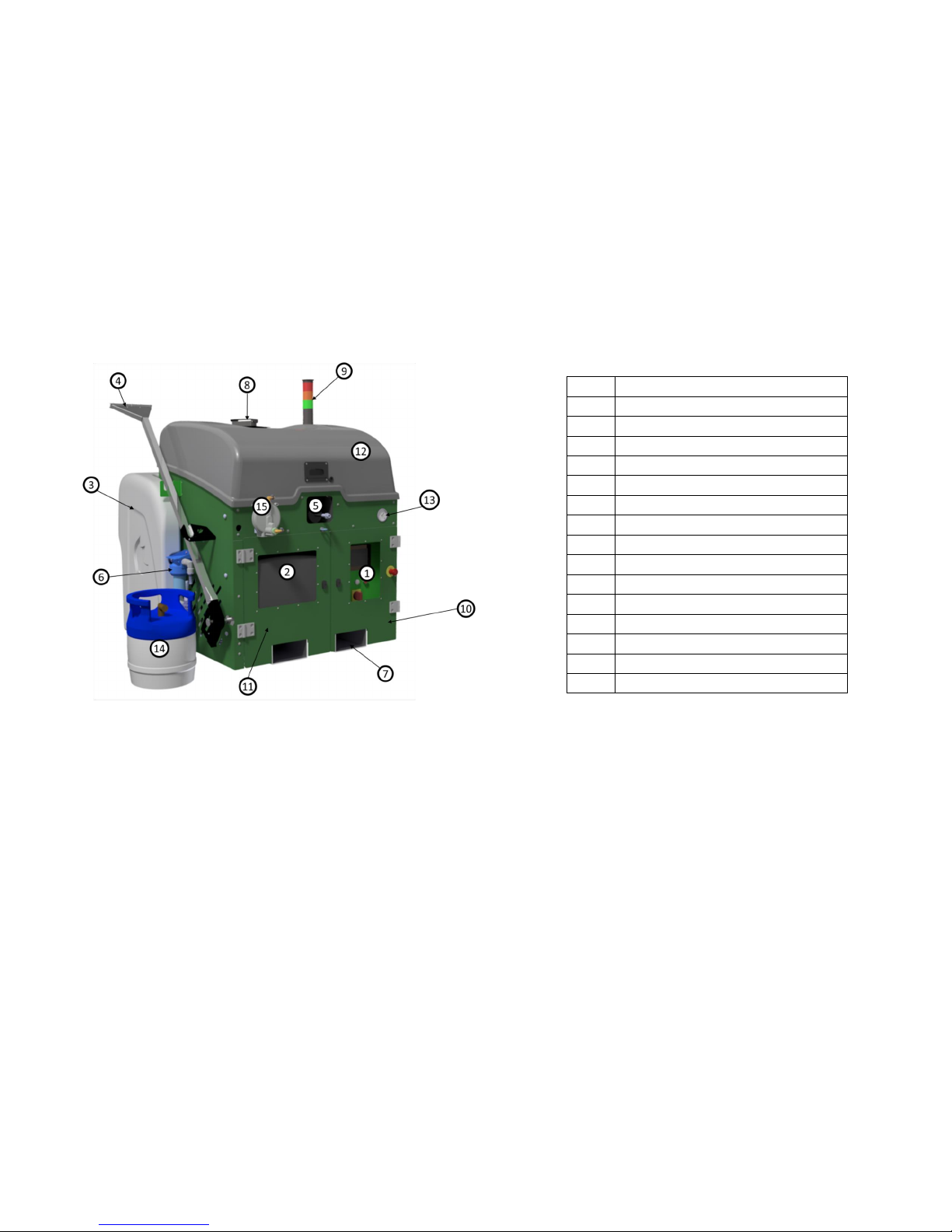
4PRODUCT DESCRIPTION _____________ 6
5FOAMSTREAM® ___________________ 12
5.1 HOW FOAMSTREAM® KILLS WEEDS______________________ 12
5.2 INDICATORS ____________________________________________ 12
5.3 CAUTION –POISONOUS WEEDS ____________________________ 13
THE EFFECT OF THE SYSTEM ON PLANTS ____________________________ 13
6PRE-START CHECKS ________________ 15
7START PROCEDURE ________________ 16
8SCREEN AND PLC NAVIGATION _______ 19
9USING THE M600 __________________ 20
10 FOAMSTREAM® APPLICATION (KILLING
WEEDS) ____________________________ 22
10.1 HOSE REEL ___________________________________________ 22
10.2 SPEED _______________________________________________ 22
10.3 USE OF THE LANCE _____________________________________ 22
10.4 TREATMENT OF THICK WEEDS ____________________________ 23
10.5 TREATMENT ___________________________________________ 23
10.6 CONFIRMATION OF TREATMENT___________________________ 23
10.7 CORRECT POSTURE _____________________________________ 23
11 SHUT-DOWN PROCEDURE ___________ 24
12 BASIC FAULT FINDING______________ 25
13 SERVICE CHECKS AND INTERVALS ____ 30
14 LOADING AND HANDLING ___________ 31
15 SCHEMATICS _____________________ 32
16 WARRANTY_______________________ 37
17 PRODUCT CERTIFICATION ___________ 39

M600 –User manual –English (EU) –16/05/2018 - ISSUE 3
4
1Safety Information
To ensure safety while operating the M600, please carefully
read the following information.
1.1 Operator Attention
WARNING
•Read and understand this user manual before operating
the M600.
•The M600 should only be used by trained operators.
•Proper PPE is to be worn at all times while operating the
M600 (see section 3).
•Major repair work should only be carried out by
professionally trained service engineers.
1.2 Carbon Monoxide Hazards
WARNING
•Boiler and generator exhaust contains poisonous carbon
monoxide gas.
•Never run the M600 indoors, even if a door or window
is open. ONLY USE IN A WELL VENTILATED AREA.
•Do not use the M600 in potentially explosive
atmospheres.
1.3 Electric Shock Hazards
WARNING
•Do not operate the M600’s electrical components with
wet hands.
•Do not expose the generator to rain, moisture, or snow.
•Always ensure electric cables are in good condition.
1.4 Fire and Burn Hazards
WARNING
•LPG and diesel are explosive and flammable. Always
ensure spark or fire source point away while refueling.
•Do not refill diesel while machine is in use.
•Clean up any overflowing fuel prior to turning on the
M600.
•Never smoke while operating the M600.
•Do not touch the working components in the M600 while
in use or immediately following use. Allow sufficient
time to cool before servicing.
•Shut off generator by closing LPG supply to prevent
unburned gas from remaining in the system.
1.5 Generator Fuel Warning
WARNING
NEVER USE PETROL IN THE M600. ONLY USE LPG TO
FUEL THE GENERATOR.
If the generator is used outside the M600 as a backup
generator and petrol is used, follow the instructions below
prior to using the M600.
•Remove all remaining petrol from generator and
clean all spills and allow to dry/evaporate
before putting the generator back inside the
M600.
•Turn the fuel switch (item 7 in Figure 11) to the OFF
position.
•Connect LPG cylinder and start as normal.

M600 –User manual –English (EU) –16/05/2018 - ISSUE 3
5
2Introduction
Thank you for purchasing the Foamstream M600!
IT IS IMPORTANT THAT ALL OPERATORS READ AND
UNDERSTAND THESE INSTRUCTIONS BEFORE USING
THE MACHINE
Having read these instructions, the operator will:
•Understand how the M600 works
•Identify key components in the M600
•Know how to carry out pre-start and start-up
procedures
•Observe safe operating practices
•Be able to effectively operate the M600
•Be able to shut down and clean the M600
•Be able to perform basic maintenance and
troubleshooting tasks
PLEASE KEEP THESE INSTRUCTIONS IN A SAFE PLACE
FOR FUTURE REFERENCE
3Important information
The following PPE (Personal Protective Equipment) are
recommended when operating the M600:
•Eye protection is required when handling
Foamstream® concentrate
•Gloves are required as the lance assembly will get hot
•Safety Footwear suitable for working in the areas
concerned is recommended
•No specific protective clothing is required, although
use of overalls and a HI-Viz vest is suggested as best
practice.
IT IS THE RESPONSIBILITY OF THE OPERATOR TO WEAR
APPROPRIATE PPE
Never operate the machine without checking that there are
adequate supplies of clean diesel, clean water, and clean
Foamstream® concentrate in the appropriate tanks.
The M600 produces VERY HOT water. This can cause
serious burns and injury if used incorrectly.
Never point the lance at people or animals as this machine
operates at high temperature and low pressure.
All personnel operating a M600 machine must be deemed
competent to do so and must be adequately trained. A copy
of the training record is available on demand.
Always check the M600 for any damage before use.
Damaged cables, hoses or connections must be reported
immediately, and the machine taken out of use until repairs
have been completed.
Use only genuine Weedingtech spare parts and
Foamstream® consumables. This will ensure the best
performance of your machine and maintain the warranty of
the unit.
The M600 must never be modified, safety interlocks
bypassed, or settings adjusted (unless specified in these
guidance notes) without Weedingtech’s written consent.
Ensure that the M600 is placed in an area where there is
adequate ventilation when in use.

M600 –User manual –English (EU) –16/05/2018 - ISSUE 3
6
Ensure that the consumable liquid (foam concentrate) is not
subject to temperatures below 5 degrees centigrade at any
time.
Ensure that both the M600 and its water tank are securely
attached to the transport vehicle. It is the responsibility of
the vehicle driver to ensure that any load is secure and that
any payload restrictions are observed. You can refer to
section 14 for more information on transport.
4Product description
The M600 weed control unit consists of:
•Foamstream®
•Water tank (270 litres)
•Hose reel (30 metres)
•Lance
The M600 houses a diesel-powered boiler, an LPG-powered
generator, a logic controller (PLC), a piston pump, a 35 litres
diesel tank, and a 15 litres Foamstream® concentrate tank.
When the water reaches 95 degrees centigrade, a valve
opens allowing water to flow from the lance (7 lpm @ 12
bar) and a venturi mixer opens to allow Foamstream®
concentrate to be injected at a ratio of 99.5 parts water to
0.5 parts concentrate. Air is added to the water and
Foamstream® mix as it exits the lance to create the foam.
Figure 1 - M600 (operator and vehicle not included)
When the machine is switched on and operational, water is
pumped at 7 litres per minute and passes through the boiler
to be heated up to a minimum of 95 degrees centigrade.
The M600 has been designed to require no manual input or
adjustment. The PLC monitors the system pressure,
temperature and flow rate to ensure optimum performance
of the unit.
NEVER OPERATE THE M600 WITHOUT FOAMSTREAM®
CONCENTRATE

M600 –User manual –English (EU) –16/05/2018 - ISSUE 3
7
A pressure relief valve and over-temperature sensor ensure
that internal pressure and temperature will not exceed 35
bar or 120 degrees centigrade in the event of a system fault.
Operation of the M600 is via the user interface at the front
of the unit (see section 7 for details).
Filters are fitted to the diesel, water and foam systems to
ensure supplies are kept clean and free from debris. These
needs to be checked daily (see section 6).
The top cover and front doors can be opened with a key to
allow access to all internal components. The generator is on
a slider and can be removed for improved access. The side
panels can be easily opened by removing the three 1/4-turn
screws on each side for maintenance purposes. Access to
the electronics is via a door on the front of the M600 which
can be opened by a key.
The standard water tank (270 litres) can be either wrap
around the unit or be separate. There are two hydraulic
connections (water supply, water return) and one electrical
connection (water sensor).
An automatic hose reel is located inside the unit to allow the
30 metres hose to be stowed safely when the M600 is not in
use. The hose comes off the right side of the reel and is
connected to the lance via a threaded collar.
M600
HEIGHT (mm)
1200
WIDTH (mm)
1000 or 1260 (with tank)
DEPTH (mm)
800 or 1110 (with tank)
WEIGHT (kg)
240 EMPTY, 270 FULL
WATER
270 LITRES
FUEL
DIESEL –35 LITRES
FOAMSTREAM
FOAMSTREAM –15 LITRES
GENERATOR OIL
0.6 LITRES SAE 5W40
PUMP OIL
0.3 LITRES SAE 5W40
FLOW RATE
7 LITRES PER MINUTE
OPERATING
PRESSURE
30 BAR ON HEAT UP, 12 BAR
TRIGGER OPEN
OPERATING
TEMPERATURE
95 –110 °C
PRESSURE
RELIEF VALVE
35 BAR
OVER
TEMPERATURE
CUT-OUT
125 °C
GENERATOR
3.2 kVA –LPG POWERED
BOILER
48 kWh –DIESEL POWERED

M600 –User manual –English (EU) –16/05/2018 - ISSUE 3
Figure 2 –Perspective view of the M600
Num.
Description
1
Control Panel
2
Generator
3
Water tank
4
Lance
5
Hose reel orifice
6
Water Filter
7
Forks entrance
8
Boiler exhaust flap
9
Warning light
10
Control panel access door
11
Generator access door
12
Top cover
13
Hydraulic pressure gauge
14
LPG cylinder
15
LPG regulator

M600 –User manual –English (EU) –16/05/2018 - ISSUE 3
9
Figure 3 - Internal components of the M600 (panels removed)
Num.
Description
1
LPG generator
2
Diesel boiler (CAUTION HOT)
3
Water pump
4
Control box
5
Automatic hose reel
6
Hydraulic plate (hydraulic components not
represented)
7
Diesel & Foamstream® filling points

M600 –User manual –English (EU) –16/05/2018 - ISSUE 3
10
Figure 4 - View of the M600 hydraulic panel (some parts hidden
for clarity)
Num.
Description
1
Lance solenoid valve
2
Lance pressure switch
3
Venturi
4
Return to tank flow switch
5
Pressure relief valve (PRV)
6
Diesel filter
7
Main flow switch
8
Diesel tank
9
Foam tank
10
Foam filter
11
Pressure gauge

M600 –User manual –English (EU) –16/05/2018 - ISSUE 3
11
Figure 5 - Closed control box (left) open (right)
Figure 6 –Detail of the switches on the front panel
Num.
Description
1
Emergency stop
2
Main contact switch
3
Boiler reset button
4
Power light
5
PLC screen (touch screen)

M600 –User manual –English (EU) –16/05/2018 - ISSUE 3
5FOAMSTREAM®
5.1 How FOAMSTREAM® kills weeds
Foamstream® uses heat to kill weeds. Water is heated to
near boiling point and then mixed with the Foamstream®
concentrate to produce foam before being applied. The foam
blanket ensures that the heat is held on the plant so that the
weeds experience hot, killing temperatures for a few
seconds. Figure 10 below explains and compares the process
to hot water and steam.
5.2 Indicators
The lances can apply large volumes of water and foam and
can be used to kill larger weeds. Foam cover, and hence heat
retention on weeds, is easier to achieve on prostrate plants
that are near the ground. Tall plants should be trodden
down either by foot or by using the lance outlet, to aid foam
cover and heat retention.
Figure 7 - Foamstream during treatment
Immediately after treatment, weeds will go dark green and
limp. This indicates that the machine is operating properly.
The weeds will die; this becomes more obvious within the
next one to seven days (depending on species and weather).
If weeds fail to go limp, temperatures may be too low or
forward speed to high.
Figure 8 - Weed immediately after treatment with Foamstream
Figure 9 - Weed 24 hours after treatment with Foamstream

M600 –User manual –English (EU) –16/05/2018 - ISSUE 3
13
If weeds go brown immediately after treatment, this could
indicate that forward speed is too slow and excessive heat
is being applied.
Figure 10 - Foamstream's triple action
Steam / Hot Water
Kills the leaves
Kills weeds
No effects on seeds
Sterilises seeds
Very weak effect on roots
Damages the root
In general, annual weeds are easier to kill than biennial or
perennial ones. Weed species that originate from desert or
semi-arid regions are more heat tolerant and will need a
slightly prolonged treatment period compared to other
species.
Biennial or perennial weeds usually have parts protected
against heat (especially regenerative parts under the soil,
the Rhizome). Foamstream is a contact application, it will
kill foliage, but many perennial and biennial plants will
regenerate. The number of repeat treatments required to
completely kill weeds depends on the species and their size.
5.3 Caution –poisonous weeds
Some poisonous weeds, such as common ragweed (Senecio
jacobaea) may still be attractive to animals after treatment
with Foamstream. When treating any area where animals
are likely to graze after treatment with Foamstream, check
for the presence of such potentially toxic weeds and remove
them or keep out of reach of animals that are at risk.
The effect of the system on plants
The M600 has been designed to operate in an urban
environment and control weed growth on both hard surfaces
and cultivated land. These weeds may be in, at, or around
kerbs and channels, footpath edges, driveways, boundaries,
obstacles etc.
Within these environments there are various plant species
that need to be controlled. These species may vary in type
and growth patterns depending on the specific geographic
location.
The system, through its unique operation, delivers a plant
kill based on thermal activity penetrating and breaking down
the cell structure of the plant.
With varying plants in the target area, it is important for the
operator have some knowledge of the weed types, sizes and

M600 –User manual –English (EU) –16/05/2018 - ISSUE 3
14
ages that they are treating, as this impacts on the speed of
operation to deliver an effective kill.
For maximum efficacy, it is important that all weeds in the
target area are in contact with the hot foam. Either flatten
tall weeds i.e. by treading or use of the lance or ensure that
the stems are ‘ring barked’ (completely surrounded by a
blanket of foam). The density of the plants and foliage is a
very important aspect for the operator to be aware of, as
this also impacts on the speed of operation. It should be
noted:
•As the height and/or density of the target plants
increases, the speed of operation will be slower.
•In a situation where regular treatment of the area is
part of a maintenance programme the weeds will
generally be easier to treat as regrowth should be
reduced.
•Regular treatment also allows increased speed of
operation, as the volume of target plants to kill will be
minimised on each maintenance cycle.

M600 –User manual –English (EU) –16/05/2018 - ISSUE 3
15
6Pre-start checks
THESE CHECKS MUST BE COMPLETED BEFORE EACH
START OF THE M600. ANY FAULTS MUST BE RECTIFIED
BEFORE THE M600 IS SWITCHED ON.
6.1 Checklist
✓The M600 is in good condition and securely attached
to the transport vehicle
✓The M600 water tank is securely attached to the
transport vehicle
✓The LPG cylinder is full, secured, and in good
condition
✓Water tank is full of clean water
✓Water filter is clean and free from debris
✓Air intakes are clear of debris
✓The lance, hose reel and hose are securely connected
and free from damage
✓Lance wear pads are not excessively worn
✓The water return pipe and water level sensor are
connected
✓Pipe/hose routes are clear of sharp edges and hot
surfaces
✓There are no signs of leaks from any pipe or
connection
✓Fuel tank is full of clean diesel fuel
✓Boiler fuel filter is clean and free from debris
✓The Foamstream® concentrate has not been subject
to temperatures below 5°C and frozen or separated
✓Foamstream® concentrate tank is full of clean
Foamstream® concentrate
✓Foamstream® filter is clean and free from debris
✓Vent screw on Foamstream® tank filler cap is open
✓Generator engine oil level is correct
✓Pump oil level is correct
✓Generator and boiler exhaust are secure and clear of
debris and obstruction
✓Fuel switch on generator is in the OFF position when
using LPG
✓Generator is switched to normal mode
✓Water feed valve is connected and in the ON (inline)
position
✓Air has been bled from water system
✓The LPG cylinder valve is connected, open, and leak
free.
CLOSE LPG CYLINDER VALVE WHEN MACHINE IS NOT IN
OPERATION
NEVER RUN THE GENERATOR WITH LPG WHILE
PETROL REMAINS IN THE GENERATOR’S PETROL
TANK

M600 –User manual –English (EU) –16/05/2018 - ISSUE 3
16
7Start procedure
✓Complete pre-start checks (see section 6)
✓Press and hold priming button on regulator
✓Start the generator by either:
•Turning the key to position Eand release to
position Dwhen engine starts (see
•Figure 11) or
•Turn the key to position Dand double press and
hold ON on the remote
✓Turn the isolator switch to position A(see
✓Figure 11), the PLC screen should illuminate (see Figure
12)
Figure 11 - Details of the switches of the front panel
✓The reset indicator (blue light) lights up and FAULT will
appear on the top right hand corner of the PLC screen
✓Press the RESET button (blue button on the front panel,
see Figure 5), the FAULT indicator goes out and you
should see the screen represented in Figure 12
✓Wait a few seconds before requesting air bleed: buttons
1or 2in Figure 12
If you have disconnected the water tank or are starting
for the first time of the day, please use “Air bleed
Total”
If you just took a break or want to perform an additional
air bleed, please select “Air bleed Partial”
When bleeding the machine, the trigger must be
pushed to allow water to flow out of the lance. Failure to
do so will cause the machine to display a fault message.
✓Once button 1or 2is pressed the bleed screen
represented in Figure 13 will appear.
✓Wait until the purge is completed. A new screen will
appear, represented in Figure 14.
✓Press START, the button turns green and the screen
represented on Figure 15 will appear.
✓The amber HEATER light will illuminate and the red
FAULT button should go out. This indicates that the
boiler has switched on and is heating the water
✓The green READY light will illuminate when the M600
has reached operating temperature and the system is
ready for use (2 –4 minutes).
AFTER A COLD NIGHT (BELOW 0 DEGREES CELSIUS),
LET THE GENERATOR RUN FOR 15 MINUTES TO WARM
UP THE MACHINE BEFORE STARTING THE PUMP OR
BLEEDING THE UNIT

M600 –User manual –English (EU) –16/05/2018 - ISSUE 3
17
Figure 12 - Start-up screen of the PLC
Num.
Description
1
Press this button to purge the M600 for 30
seconds.
2
Press this button to purge the M600 for 10
seconds.
3
Indication message.
4
Air bleed status indicator.
5
Menu access
Figure 13 - Bleed screen of the PLC
Figure 14 - Start screen of the PLC
Num.
Description
1
Start button
2
Boiler water input temperature
3
Boiler water output temperature
4
Indication message
5
Menu access
12
3
4
5
1
2 3
4
5

M600 –User manual –English (EU) –16/05/2018 - ISSUE 3
18
Figure 15 - Running screen of the PLC

M600 –User manual –English (EU) –16/05/2018 - ISSUE 3
19
8Screen and PLC navigation
When the M600 is ready to start, the screen below will
appear (same as Figure 14)
To access the menu, click on the “Menu” button on the top
left-hand side of the screen. The screen in will appear.
Figure 16 - Menu screen
Num.
Description
1
Return to main page
2
Go to summary screen
3
Purge
4
Language and units selection
5
Fault summary panel
6
Maintenance mode
Users have no need to access pages 5and 6. Page 6is
restricted by a password. The screens are summarized in
the table below (in the same order as is Figure 16)
1
2 3
4
5
1 2 3
4 5 6

M600 –User manual –English (EU) –16/05/2018 - ISSUE 3
20
9Using the M600
The M600 control panel gives important feedback on the
status of the M600:
Status
Red
Orange
Green
Ready
Fixed
Fixed
Stand-by
Fixed
Flashing
Boiler active
Fixed
Boiler fault
Fixed
Water tank too hot
Flashing
Level sensor low
Flashing
Boiler overtemp.
Fixed
Flashing
POWER LIGHT - WHITE
When the generator is on, this light should be illuminated. If
the generator does not start, then the generator plug should
be checked. If the generator breaker position is correct and
the generator does not start the M600 should be checked by
a competent service engineer.
AMBER HEATER LIGHT
If the amber light is illuminated the water is below 96
degrees centigrade and is being heated. If the amber light
does not illuminate, and the red fault light stays on, there
may be a system fault (see below)
GREEN READY LIGHT
When this light is illuminated the M600 is ready for use. If
the green light is not illuminated the water may need
heating (amber light will be on) or there is a system fault
(red fault light will be on, see below).
FLASHING ORANGE LIGHT
If the amber light is flashing the water in the water tank is
too hot. If water in the water tank exceeds 45°C the boiler
will shut down. The water tank will need to be drained and
refilled with cold water, or the level topped up with cold
water.
BLUE RESET LIGHT
The blue reset light should switch off when the reset button
is pressed during start up. If the light stays on there is an
electrical fault which needs rectification. The M600 should
be switched off until the fault has been corrected.
FLASHING BLUE RESET LIGHT
A flashing blue reset light indicates a boiler fault. The M600
must be switched off and checked by a competent service
engineer.
RED FAULT LIGHT
The red fault light will illuminate at start up until the green
button is pressed and the amber light illuminates. If the red
light stays on, and the amber light fails to illuminate, the
system may need to be bled to remove air (see section 7).
If the red light fails to switch off after bleeding there is a
system fault. The M600 should be switched off until the fault
has been corrected by a competent service engineer.
Other manuals for Foamstream M600
1
Table of contents
Other weedingtech Lawn And Garden Equipment manuals