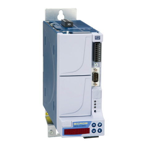
WEG SCA06 User manual

Motors | Automation | Energy | Transmission & Distribution | Coatings
Ethernet
SCA06
User’s Guide

Ethernet User’s Guide
Series: SCA06
Language: English
Document Number: 10004473905 / 00
Build 529
Publication Date: 09/2016

Contents
Contents
About the Manual ..................................................................................................... 6
1 Equipment Characteristics in Ethernet Network ............................................................. 7
1.1 Modbus TCP specific characteristics ....................................................................... 7
1.2 EtherNet/IP specific characteristics ......................................................................... 7
1.3 PROFINET IO specific characteristics ...................................................................... 7
2 Ethernet Overview ............................................................................................... 8
2.1 Ethernet Technology ......................................................................................... 8
3 Interfaces Description ........................................................................................... 9
3.1 Ethernet Accessory .......................................................................................... 9
3.2 Connectors .................................................................................................. 9
3.3 Indication LEDs .............................................................................................. 9
4 Network Installation .............................................................................................. 11
4.1 IP Address ................................................................................................... 11
4.2 Communication Rate ........................................................................................ 11
4.3 Cable ......................................................................................................... 11
4.4 Network Topology ........................................................................................... 12
4.5 Recommendations for Grounding Connection and Cable Routing ........................................ 13
5 Parameterization ................................................................................................. 14
5.1 Symbols for the Properties Description ..................................................................... 14
P0202 – Operation Mode........................................................................................... 14
P0662 – Communication Error Behavior................................................................. .......... 14
P0800 – Ethernet Module Identification ............................................................................ 15
P0801 – Ethernet Communication Status ......................................................................... 15
P0803 – Ethernet Baud Rate ....................................................................................... 16
P0806 – Modbus TCP Watchdog .................................................................................. 16
P0810 – IP Address Configuration ................................................................................. 16
P0811 – IP Address 1 .............................................................................................. 17
P0812 – IP Address 2 .............................................................................................. 17
P0813 – IP Address 3 .............................................................................................. 17
P0814 – IP Address 4 .............................................................................................. 17
P0815 – Subnet CIDR ............................................................................................. 17
P0816 – Gateway 1................................................................................................. 18
P0817 – Gateway 2................................................................................................. 18
P0818 – Gateway 3................................................................................................. 18
P0819 – Gateway 4 ................................................................................................ 18
P0820 ... P0831 – Ethernet Read Words #5 ... #16 ............................................................. 18
P0835 ... P0846 – Ethernet Write Words #5 ... #16 ............................ ................................. 19
P0849 – Update Ethernet Configuration ........................................................................... 20
6 I/O Words with Specific Function .............................................................................. 21
6.1 Input Words – (Slave →Master) ............................................................................ 21
6.1.1 1st – Status Word .................................................................................... 21
6.1.2 2nd – Motor Speed .................................................................................. 21
6.1.3 3rd – Torque Current ................................................................................. 22
SCA06 | 3

Contents
6.1.4 4th – Present Control Mode ................................................................ ......... 22
6.2 Output Words – (Master →Slave) .......................................................................... 22
6.2.1 1st – Control Word ................................................................................... 22
6.2.2 2nd – Speed Reference .............................................................................. 23
6.2.3 3rd – Torque Reference .............................................................................. 23
6.2.4 4th – Control Mode ......................................................................... ......... 23
7 Modbus TCP ...................................................................................................... 24
7.1 Indication LEDs .............................................................................................. 24
7.2 Available Functions ......................................................................... ................. 24
7.3 Memory Map ................................................................................................. 24
7.3.1 Parameters .......................................................................................... 24
7.3.2 Memory Markers .................................................................................... 25
7.4 Communication Errors ....................................................................................... 25
7.5 Startup Guide ................................................................................................ 26
7.5.1 Installing the Ethernet Module ....................................................... ............... 26
7.5.2 Configuring the Drive ..................................... ........................................... 26
7.5.3 Configuring the Master .............................................................................. 27
7.5.4 Communication Status .............................................................................. 27
7.5.5 Operation Using Process Data ....................................................... ............... 27
8 EtherNet/IP ....................................................................................................... 28
8.1 Indication LEDs .............................................................................................. 28
8.2 Cyclic Data ................................................................................................... 28
8.3 Acyclic Data .................................................................................................. 28
8.4 EDS File ................................................................ ...................................... 28
8.5 Modbus TCP Connections ......................................................................... ......... 29
8.6 Startup Guide ................................................................................................ 29
8.6.1 Installing the Ethernet Module ....................................................... ............... 29
8.6.2 Configuring the Drive ..................................... ........................................... 29
8.6.3 Configuring the Master .............................................................................. 29
8.6.4 Communication Status .............................................................................. 30
8.6.5 Operation Using Process Data ....................................................... ............... 30
9 PROFINET ........................................................................................................ 31
9.1 Indication LEDs .............................................................................................. 31
9.2 Cyclic Data ................................................................................................... 31
9.3 Acyclic Data .................................................................................................. 31
9.4 XML File – GSDML .................................................................................. ........ 31
9.5 Modbus TCP Connections ......................................................................... ......... 32
9.6 Startup Guide ................................................................................................ 32
9.6.1 Installing the Ethernet Module ....................................................... ............... 32
9.6.2 Configuring the Drive ..................................... ........................................... 32
9.6.3 Configuring the Master .............................................................................. 32
9.6.4 Communication Status .............................................................................. 33
9.6.5 Operation Using Process Data ....................................................... ............... 33
10 WEB Server ....................................................................................................... 34
11 Faults and Alarms ................................................................................................ 35
F0047/A0147 - Ethernet Offline .................................................................................... 35
SCA06 | 4

Contents
F0048/A0148 - Ethernet interface access error ................................................................... 35
SCA06 | 5

About the Manual
ABOUT THE MANUAL
This manual supplies the necessary information for the operation of the SCA06 servo drive using the Ethernet interface.
This manual must be used together with the SCA06 user’s manual and programming manual.
SCA06 | 6

Equipment Characteristics in Ethernet Network
1 EQUIPMENT CHARACTERISTICS IN ETHERNET NETWORK
Below are listed the main features for Ethernet communication module for SCA06 servo drive.
There are 3 different acessories, according to the specified communication protocol:
–ECO5: EtherNet/IP protocol.
–ECO6: Modbus TCP protocol.
–ECO7: PROFINET IO protocol.
The interface follows the Fast Ethernet 100BASE-TX standard.
It allows communication using the 10 or 100 Mbps rates in half or full duplex mode.
It has a built-in, two-port Ethernet switch.
The Ethernet ports work with Auto-MDIX (automatic medium-dependent interface crossover), a technology which
automatically detects the type of cable used and configures the connection accordingly, eliminating the need of
cross-over cables.
The interface also makes available a Web server (HTTP).
1.1 MODBUS TCP SPECIFIC CHARACTERISTICS
Operates as Modbus TCP server.
The server provides up to 4 simultaneous Modbus TCP connections.
Allows data communication for equipment operation and parameterization, as well as markers and data used for
SCA06 ladder programming.
1.2 ETHERNET/IP SPECIFIC CHARACTERISTICS
It is supplied with an EDS file for the network master configuration.
Allows up to 16 input words and 16 output words for cyclic data communication.
Acyclic data available for parameterization.
Device Level Ring (DLR) and linear network topology supported.
It features up to 2 Modbus TCP connections.
1.3 PROFINET IO SPECIFIC CHARACTERISTICS
It is supplied with a XML file for the network master configuration.
Allows up to 16 input words and 16 output words for cyclic data communication.
Acyclic data available for parameterization.
It features up to 2 Modbus TCP connections.
SCA06 | 7

Ethernet Overview
2 ETHERNET OVERVIEW
Following it is presented general information about the Ethernet technology.
2.1 ETHERNET TECHNOLOGY
Ethernet is a technology for interconnecting local area networks (LAN) based on frames forwarding. It defines wiring
and electrical signals for the physical layer, the frame format and protocol for media access control layer (MAC) of the
OSI model.
Ethernet, however, mainly defines the physical medium and the frame format. Based on Ethernet, multiple protocols
and higher-level services were specified and developed in order to perform desired activities over a network, such as
packet routing, connection establishment, sending and receiving files, etc. Several of these protocols have also been
widely disseminated and employed, such as IP, TCP, UDP, FTP, HTTP.
Widely used to interconnect computers in the office environment, the Ethernet technology also started being used in
industrial environments for interconnection of field devices. For industrial environment also emerged different com-
munication protocols based on Ethernet, among which we can mention Modbus TCP, EtherNet/IP, PROFINET.
SCA06 | 8

Interfaces Description
3 INTERFACES DESCRIPTION
The SCA06 servo drive uses an accessory to provide a Ethernet interface for communication.
3.1 ETHERNET ACCESSORY
Supplied items:
–Installation guide.
–Ethernet accessory.
XNOTE!
There are 3 different accessories, according to the specified communication protocol:
ECO5: EtherNet/IP protocol.
ECO6: Modbus TCP protocol.
ECO7: PROFINET IO protocol.
It is important to use the accessory model according to the desired protocol for application.
3.2 CONNECTORS
The accessory for Ethernet communication has two RJ45 connectors for network connection. The connector pin
out follows the Fast Ethernet 100BASE-TX standard, using two pairs of cables for data transmission and reception.
The housings of the Ethernet connectors, which are normally connected to the cable shield, have connections be-
tween themselves and to the protective earth via an RC circuit.
3.3 INDICATION LEDS
The Ethernet accessory has an LED indicator on the Ethernet port, and two bi-color status LEDs. These LEDs have
the following functions and indications:
SCA06 | 9

Interfaces Description
Link
NS
Figure 3.1: Ethernet Connectors and LEDs
Table 3.1: Ethernet Indication LEDs
LED Color Function
Link Green LED for link and activity indication.
Network Status
(NS)
Bicolor
(Green/Red)
Has a different behavior depending on the communication protocol,
which is described in the section for each protocol.
Table 3.2: LED Link
State Description
Off No link or powered off.
Green, solid Link up, no activity.
Green, flashing Link up and activity.
SCA06 | 10

Network Installation
4 NETWORK INSTALLATION
This chapter presents recommendations related to equipment installation in an Ethernet network.
4.1 IP ADDRESS
Every equipment in an Ethernet network needs an IP address and subnet mask.
The IP addressing is unique in the network, and each equipment must have a different IP. The subnet mask is used
to define which IP address range is valid in the network.
The SCA06 servo drive allows the use of two methods for programming these features, programmable via P0810:
DHCP: enable the configuration of the SCA06 via DHCP server. The DHCP can automatically assign IP addresses,
subnet mask, etc. to the devices on the network. The configurations performed via parameters are disregarded.
Parameters: uses the configurations of IP address, mask and gateway as programmed on equipment parameters.
XNOTE!
After changing these properties, for the changes to take effect, the equipment must be turned off and
on again, or requesting the Ethernet settings update via P0849.
4.2 COMMUNICATION RATE
The Ethernet interfaces of the SCA06 servo drive can communicate using the 10 or 100 Mbps rates in half or full
duplex mode.
The baud rate is programmed at P0803.
XNOTE!
It is important that, for each Ethernet connection made between two points, the baud rate and the
duplex mode are set to the same option. If the option AUTO is used in one of the points, you must
set the other point also to AUTO, or to half duplex mode.
For PROFINET IO interface, the baud rate is locked to 100 Mbps as required by the protocol.
4.3 CABLE
Recommended characteristics for the cable:
Standard Ethernet cable, 100Base-TX (FastEthernet), CAT 5e or higher.
Shielded cable.
Maximum length between devices: 100 m.
For installation, it is recommended the use of shielded Ethernet cables specific for use in industrial environment.
SCA06 | 11

Network Installation
4.4 NETWORK TOPOLOGY
To connect SCA06 servo drive in an Ethernet network, usually the star connection is made using an industrial switch.
Figure 4.1: Star topology
It is also possible to make the connection in daisy chain, allowing a topology equivalent to a bus.
Figure 4.2: Daisy chain topology
XNOTE!
When the equipment is turned off, the built-in switch is also deactivated, preventing communication
with the subsequent equipment.
A switch with support to the redundancy technology enables the use of the ring topology.
Figure 4.3: Ring topology
SCA06 | 12

Network Installation
4.5 RECOMMENDATIONS FOR GROUNDING CONNECTION AND CABLE ROUTING
The correct connection with the ground decreases problems caused by interference in an industrial environment. The
following are some recommendations about grounding and cable routing:
Always use shielded twisted pair Ethernet cables and connectors with metallic housing.
Connect the equipment grounding via grounding terminal. Avoid the cable connection on multiple grounding
points, especially where there are grounds with different potentials.
Pass signal cables and communication cables in dedicated pathways. Prevent laying these cables next to power
cables.
SCA06 | 13

Parameterization
5 PARAMETERIZATION
Next, the SCA06 servo drive parameters related to the Ethernet communication will be presented.
5.1 SYMBOLS FOR THE PROPERTIES DESCRIPTION
RO Read-only parameter
RW Read/write parameter
CFG Parameter that can be changed only with motor stopped.
ETH Parameter visible on the HMI if the product has the Ethernet interface installed
P0202 – OPERATION MODE
Range: 1 = Torque Mode
2 = Speed Mode
3 = No function
4 = Ladder Mode
5 = CANopen/DeviceNet/EtherCAT
6 = Profibus DP/Ethernet
Default: 2
Properties: RW
Description:
This parameter defines the operating mode for SCA06 servo drive, allowing to program which mode is desired for
the motor control, and what is the control source for the device.
In order to control de equipment via Ethernet network, it’s necessary to use mode 6 = Ethernet. In case this mode
is programmed, commands and references for the product operation will be provided by cyclic data via Ethernet
network.
XNOTE!
The control of equipment using these objects is only possible by selecting the desired option in this
parameter, but Ethernet communication can be used in any operating mode.
The Ethernet interface allows speed and torque control of the SCA06 servo drive. To perform po-
sitioning functions, the Ladder operating mode must be used, developing a Ladder application
program and using user’s parameters as the interface with the network master to control and mon-
itor the equipment.
P0662 – COMMUNICATION ERROR BEHAVIOR
Range: 0 = Show Alarm
1 = Generate Fault
2 = Run STOP function
3 = Disable drive
Default: -
Properties: RW
Description:
This parameter allows selecting which action should be executed by the equipment, if it is controlled via network and
a communication error is detected.
SCA06 | 14

Parameterization
Table 5.1: Option for parameter P0662
Option Description
0 = Show Alarm If a communication error occurs, only indicates alarm in the keypad. If the communica-
tion is reestablished, the alarm indication is automatically removed.
1 = Generate Fault Instead of an alarm, a communication error causes a fault in the equipment, and it is
necessary to reset the failure to return to normal operation.
2 = Run STOP function It will indicate an alarm along with the execution of the STOP command. To start oper-
ation again, it is necessary to run the fault reset or disable the drive.
3 = Disable drive It will indicate an alarm along with the execution of the disable command.
The following events are considered communication errors:
Ethernet communication:
Alarm A0147/Fault F0047: communication error with Ethernet master.
Alarm A0148/Fault F0048: Ethernet interface error.
P0800 – ETHERNET MODULE IDENTIFICATION
Range: 0 = Not Identified
1 = Modbus TCP
2 = EtherNet/IP
3 = PROFINET IO
Default: -
Properties: RO, ETH
Description:
It allows identifying the Ethernet module type connected to the equipment.
Table 5.2: P0800 indications
Indication Description
0 = Not Identified Module not connected / not identified.
1 = Modbus TCP Ethernet module for communication with Modbus TCP protocol.
2 = EtherNet/IP Ethernet module for communication with EtherNet/IP protocol.
3 = PROFINET IO Ethernet module for communication with PROFINET IO protocol.
P0801 – ETHERNET COMMUNICATION STATUS
Range: 0 = Setup
1 = Init
2 = Wait Comm
3 = Idle
4 = Data Active
5 = Error
6 = Reserved
7 = Exception
8 = Access Error
Default: -
Properties: RO, ETH
Description:
It allows identifying the Ethernet communication status.
SCA06 | 15

Parameterization
Table 5.3: P0801 indications
Indication Description
0 = Setup Module identified, waiting configuration data (automatic).
1 = Init Module performing interface initialization procedure (automatic).
2 = Wait Comm Initialization finished, but no communication with master.
3 = Idle Communication with master established, but in Idle mode or Program mode.
4 = Data Active Communication with master established and performing normal I/O data handling. ”On-
line”.
5 = Error Communication error detected.
6 Reserved
7 = Exception Major fault detected by the Ethernet interface. Requires interface reinitialization.
8 = Access error Major fault detected between device and Ethernet interface. Requires interface reinitial-
ization.
P0803 – ETHERNET BAUD RATE
Range: 0 = Auto
1 = 10Mbit/s, half duplex
2 = 10Mbit/s, full duplex
3 = 100Mbit/s, half duplex
4 = 100Mbit/s, full duplex
Default: 0
Properties: RW, ETH
Description:
It allows to set the desired baud rate for the Ethernet interface.
XNOTE!
For the changes in this parameter be effective, the equipment must be powered off and on again,
or an update must be performed by P0849.
For PROFINET interface, the baud is locked to 100Mbit/s as required by the protocol.
P0806 – MODBUS TCP WATCHDOG
Range: 0.0 to 65.5 s Default: 0.0
Properties: RW, ETH
Description:
It allows programming a time limit for the detection of Ethernet offline error, for Modbus TCP protocol. If the SCA06
remains without receiving valid telegrams longer than the time programmed in this parameter, it will be considered
that a communication error has occurred, the alarm A147 will be showed on the HMI and the option programmed in
P0662 will be executed.
After being powered up, the SCA06 starts counting this time from the first received valid telegram. The value 0.0
disables this function.
XNOTE!
For the changes in this parameter be effective, the equipment must be powered off and on again, or
an update must be performed by P0849.
SCA06 | 16

Parameterization
P0810 – IP ADDRESS CONFIGURATION
Range: 0 = Parameters
1 = DHCP
Default: 1
Properties: RW, ETH
Description:
It allows to choose how to set the IP address for the Ethernet modules.
Table 5.4: P0810 options
Option Description
0 = Parameters The settings for IP address, sub-net mask and gateway shall be done by means of
parameters P0811 to P0819.
1 = DHCP Enables DHCP function. A DHCP server should set the IP address, sub-net mask and
gateway through network.
XNOTE!
For the changes in this parameter be effective, the equipment must be powered off and on again, or
an update must be performed by P0849.
P0811 – IP ADDRESS 1
P0812 – IP ADDRESS 2
P0813 – IP ADDRESS 3
P0814 – IP ADDRESS 4
Range: 0 ... 255 Default: 192.168.0.10
Properties: RW, ETH
Description:
If P0810 = 0 (parameters), these parameters allow you to program the IP address of the Ethernet module. For other
option of P0810, these parameters have no function.
Each parameter programs one octet of the IP address, where the P0811 is the most significant octet. The pro-
grammed IP address, then, has the format “P0811.P0812.P0813.P0814”.
XNOTE!
For the changes in this parameter be effective, the equipment must be powered off and on again, or
an update must be performed by P0849.
P0815 – SUBNET CIDR
Range: 1 ... 31 Default: 24
Properties: RW, ETH
Description:
If P0810 = 0 (parameters), this parameters allow you to program the sub-net mask for the Ethernet module. The
subnet mask can usually be programmed using a notation with 4 octets separated by dots, or CIDR notation, in
which the value is the number of bits with value “1” in the subnet mask. For other option of P0810, this parameter
has no function.
SCA06 | 17

Parameterization
The following table shows the allowed values for the CIDR notation and equivalent dot notation for the subnet mask:
Table 5.5: P0815 options
CIDR Sub-net mask CIDR Sub-net mask
1 128.0.0.0 17 255.255.128.0
2 192.0.0.0 18 255.255.192.0
3 224.0.0.0 19 255.255.224.0
4 240.0.0.0 20 255.255.240.0
5 248.0.0.0 21 255.255.248.0
6 252.0.0.0 22 255.255.252.0
7 254.0.0.0 23 255.255.254.0
8 255.0.0.0 24 255.255.255.0
9 255.128.0.0 25 255.255.255.128
10 255.192.0.0 26 255.255.255.192
11 255.224.0.0 27 255.255.255.224
12 255.240.0.0 28 255.255.255.240
13 255.248.0.0 29 255.255.255.248
14 255.252.0.0 30 255.255.255.252
15 255.254.0.0 31 255.255.255.254
16 255.255.0.0
XNOTE!
For the changes in this parameter be effective, the equipment must be powered off and on again, or
an update must be performed by P0849.
P0816 – GATEWAY 1
P0817 – GATEWAY 2
P0818 – GATEWAY 3
P0819 – GATEWAY 4
Range: 0 ... 255 Default: 0.0.0.0
Properties: RW, ETH
Description:
If P0810 = 0 (parameters), these parameters allow you to program the IP address of the default gateway for the
Ethernet modules. For other option of P0810, these parameters have no function.
Each parameter programs one octet of the gateway address, where the P0816 is the most significant octet. The
programmed gateway IP address, then, has the format “P0816.P0817.P0818.P0819”.
XNOTE!
For the changes in this parameter be effective, the equipment must be powered off and on again, or
an update must be performed by P0849.
P0820 ... P0831 – ETHERNET READ WORDS #5 ... #16
Range: 0 ... 9999 Default: 0
Properties: RW, ETH
Description:
These parameters allow programming the number of read words (inputs: slave →master), as well as the content of
SCA06 | 18

Parameterization
each word.
The first four read words are pre-defined, representing the value of the status word, motor speed, torque current
and present control mode (refer to item 6.1), and are always sent to the network master. The words #5 to #16 can
be programmed by the user. By using these parameters it is possible to program the number of another parameter
whose content must be made available at the network master input area. If, for instance, one wants to read from the
SCA06 servo drive the motor current in Amps, one must program the value 3 in one of these parameters, because
the parameter P0003 is the one that contains this information. It is worthwhile to remind that the value read from any
parameter is represented with a 16 bit word. Even if the parameter has decimal resolution, the value is transmitted
without the indication of the decimal places. E.g., if the parameter P0003 has the value 4.7A, the value supplied via
the network will be 47.
The number of read words is defined by programming zero in the last parameter required for communication. Besides
the four predefined words, it will also be added to the input area the words programmed in these parameters if the
contents programmed for these parameters is different from zero. The first parameter set to zero disables the use of
itself and the other parameters in the sequence. For example, if you set P0820 = 0, only four predefined read words
(state, speed, torque current and present control mode) will be communicated with the master.
Table 5.6: Read words programming
Input Number of read words
(slave →master)
Fixed
Status word
4567
16
Motor speed
Torque current
Present control mode
Programmable
Programmable in P0820
Programmable in P0821
Programmable in P0822
.
.
.
Programmable in P0831
The same number of words programmed into the equipment must be programmed in the master when configuring
the network.
XNOTE!
If, after parameter settings, the number of words changes, to make the new configuration effective the
equipment must be powered off and on again, or an update must be performed by P0849.
P0835 ... P0846 – ETHERNET WRITE WORDS #5 ... #16
Range: 0 ... 9999 Default: 0
Properties: RW, ETH
Description:
These parameters allow programming the number of write words (outputs: master →slave), as well as the content
of each word.
The first four write words are pre-defined, representing the value of the control word, speed reference, torque reference
and control mode (refer to item 6.2), and are always received from the network master. The words #5 to #16 can
be programmed by the user. By using these parameters it is possible to program the number of another parameter
whose content must be made available at the network master output area. If, for instance, one wants to write to
the SCA06 servo drive the ramp for STOP function, one must program the value 105 in one of these parameters,
because the parameter P0105 is the one to program this information. It is worthwhile to remind that the value written
from any parameter is represented with a 16 bit word. Even if the parameter has decimal resolution, the value is
transmitted without the indication of the decimal places. E.g., if the parameter P0105 has the value 5.0s, the value
supplied via the network will be 50.
SCA06 | 19

Parameterization
The number of write words is defined by programming zero in the last parameter required for communication. Besides
the four predefined words, it will also be added to the output area the words programmed in these parameters if the
contents programmed for these parameters is different from zero. The first parameter set to zero disables the use of
itself and the other parameters in the sequence. For example, if you set P0835 = 0, only four predefined write words
(control, speed reference, torque reference and control mode) will be communicated with the master.
Table 5.7: Write words programming
Output Number of write words
(master →slave)
Fixed
Control word
4567
16
Speed reference
Torque reference
Control mode
Programmable
Programmable in P0835
Programmable in P0836
Programmable in P0837
.
.
.
Programmable in P0846
The same number of words programmed into the equipment must be programmed in the master when configuring
the network.
XNOTE!
If, after parameter settings, the number of words changes, to make the new configuration effective the
equipment must be powered off and on again, or an update must be performed by P0849.
P0849 – UPDATE ETHERNET CONFIGURATION
Range: 0 = Normal Operation
1 = Update configuration
Default: 0
Properties: RW, ETH
Description:
It allows you to force a reset of the Ethernet interface, to update the settings made in the device parameters. When
setting this parameter to “1”, the Ethernet interface is restarted, resulting in loss of communication during this process.
After the process is complete, the parameter switch automatically to “0”.
SCA06 | 20
Other manuals for SCA06
3
Table of contents
Other WEG Servo Drive manuals
Popular Servo Drive manuals by other brands

Clinton
Clinton MINI-TAURUS 990 Service manual

Mitsubishi Electric
Mitsubishi Electric MR-J4W2-0303B6 instruction manual

Leadshine
Leadshine EL7-EC Series user manual

turck
turck IM72-11Ex/L manual

Lenze
Lenze L-force EWS0006 Mounting instructions

Mitsubishi Electric
Mitsubishi Electric Melservo-J3 Series MR-J3-B manual