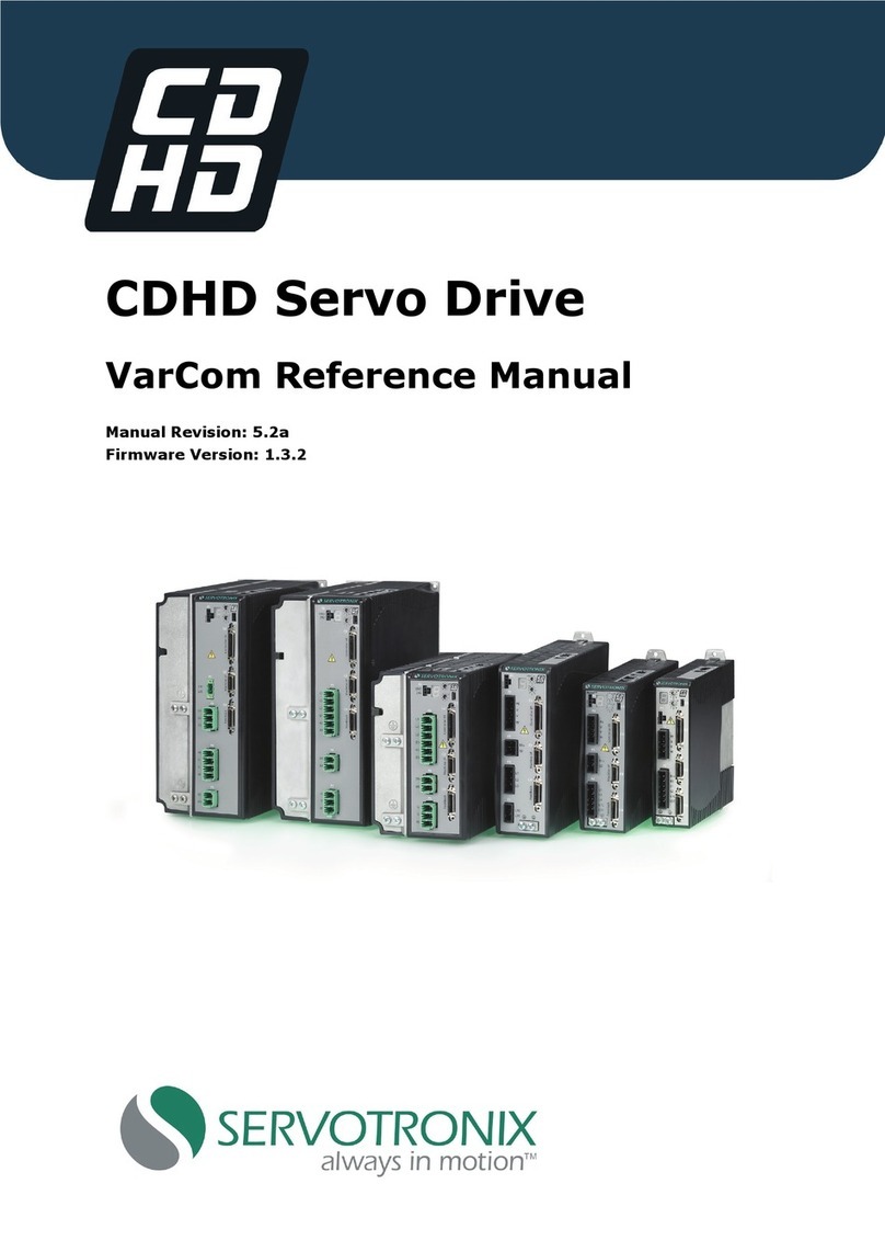
Servotronix CDHD Series User manual

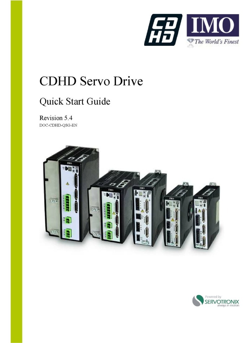
CDHD Servo Drive
User Manual
1 2 0 / 2 4 0 VAC a nd 4 0 0 / 4 8 0 VAC
Revision : 8 .6
Fir m w a re Version 1 .4 1 .x
Soft w are Version: 1 .41 .x .x
DOC-CD H D -UM -EN
I n t r od uct ion 1
Sa fet y a nd
St a nda r ds 2
Sp e cif ica t io ns 3
W iring 4
Drive Setup 5
Applica t io n Se t u p 6
M ot or Se t u p 7
Oper a t ion 8
Tuning 9
Dia gnost ics and
Tr oubleshooting 1 0
Acce ssor ies 1 1


CDHD
User Manual 3
Re v isio n H ist or y
Docum ent
Re vision
D a t e Rem arks
8.6 Feb. 2017 Firm ware 1. 41.10. Minor content update.
8.5 Jan.2017 Firmware 1.41.10. Updated faults/ warnings/ errors. Updated m ult i-
turn encoder. Added note in Standards Com pliance.
8.4 Oct. 2016 Firm ware 1. 41.4. Updated info: hazardous m aterials (ROHS 2.0
China); mounting; cont roller I / F; gearing opmode; firmware update
over EtherCAT; serial baud rate
8.3 May 2016 Firm ware 1.41.2.
8.2 May 2016 Firm ware 1.41.2. General release.
8.1 Feb.2016 Firm ware 1.40.0. Lim ited release.
8.0 Nov. 2015 Firm ware 1.20.7. Internal release.
7.2 Mar.2015 Firmware 1.15.24
7.0/ 7.1 Jan. 2015 Firmware 1.15.xx
6.0/ 6.1 Mar.2014 Firm ware 1.4.6
5.2 Jan. 2014 Firm ware 1. 4.5
5.1 Oct . 2013 Firmware 1.4.4.
5.0 Sep. 2013 Firm ware 1. 4.x.
Copyr ight N ot ice
© 2017 Servotronix Motion Control Ltd.
All right s reserved. No part of t his work m ay be reproduced or t ransm it ted in any
form or by any m eans without prior writ ten perm ission of Servot ronix Motion
Control Ltd.
Disclaim er
This product docum entation was accur ate and reliable at t he t im e of it s release.
Servotronix Motion Control Ltd. reserves the right to change the specifications of
the product described in this m anual without notice at any tim e.
Tra dem a rks
ServoStudio and sensAR are t radem arks of Servotronix Motion Control Ltd.
CANopen and CiA are regist ered t radem arks of the CAN in Autom at ion User's
Group
EtherCAT is a regist ered tradem ark of Beckhoff Aut om at ion Gm bH
EnDat is a registered trademark of Dr. Johannes Heidenhain Gm bH
HIPERFACE is a registered tradem ark of Sick Stegm ann Gm bh
BiSS-C is a regist er ed t radem ark of iC-Haus Gm bH
Windows is a registered tradem ark of Microsoft Corporat ion

CDHD
4 User Manual
Con t a ct I nfo rm a t ion
Servotronix Motion Control Ltd.
21C Yagia Kapayim Street
Pet ach Tikva 49130
I srael
Tel: + 972 (3) 927 3800
Fax: + 972 (3) 922 8075
Website: www.servotronix.com
Technica l Support
If you need assistance with the installation and configuration of the CDHD dr ive,
contact Servotronix Technical Support: tech.support@servot ronix.com
Cu st om e r Se rvice
Servot ronix is com m it ted t o delivering qualit y cust om er service and support for
all our product s. Our goal is to provide our custom ers wit h the information and
resources so that they are available, without delay, if and when they are needed.
I n order t o serve in t he m ost effective way, we recom m end that you cont act
your local sales represent at ive for or der st at us and delivery inform ation, product
information and literature, and application and field technical assistance. I f you
are unable to contact your local sales representative for any reason, please use
the m ost relevant of the contact details below:
For Technical Support, contact:
tech.support@servot ronix.com
To order products, contact: orders@servot ronix.com
For all other inquiries regarding CDHD drives or other Servot ronix product s,
contact :
custom er.service@servotronix.com
W a r ra n t y
The Product Warranty statement can be found in the Term s and Conditions
docum ent on t he Servotronix website: servotronix.com / term s-conditions
Un packing
The package contains the CDHD drive only.
Upon receipt, open the package and rem ove all packing m aterials.
Check to ensure there is no visible damage to the CDHD drive. I f dam age is
det ect ed, notify the carrier im m ediat ely.

CDHD
User Manual 5
Cont ent s
1I n t r od uct ion ________________________________________________ 9
1.1 CDHD Product Overview ............................................................................. 9
1.2 CDHD Models ...........................................................................................10
1.3 Ordering Information ................................................................................11
1.4 Documentation Set for CDHD .....................................................................12
2Sa fet y a nd St a ndards ________________________________________ 1 3
2.1 Safety Overview .......................................................................................13
2.2 Saf et y Sym bols ........................................................................................13
2.3 Safet y I nstructions....................................................................................13
2.4 St andards Com pliance...............................................................................15
2.5 STO Certification and Reliability Data ..........................................................16
2.6 Material Safety Data .................................................................................16
3Spe cifica t ion s ______________________________________________ 1 7
3.1 Dimensions ..............................................................................................17
3.2 Mechanical and Electrical Specifications ....................................................... 21
3.3 Control Specifications................................................................................30
3.4 Protective Functions and Environm ental Specifications................................... 32
3.5 Com m unicat ion Specifications ....................................................................32
3.6 I / O Specifications .....................................................................................33
3.7 Mot or Feedback Specificat ions ....................................................................35
4W iring ____________________________________________________ 3 7
4.1 CDHD-1D5/ CDHD-003 (120/ 240 VAC) Wiring and Pin Assignm ents.................37
4.2 CDHD-4D5/ CDHD-006 ( 120/ 240 VAC) Wiring and Pin Assignm ent s................. 41
4.3 CDHD-008/ CDHD-010/ CDHD-013 ( 120/ 240 VAC) Wiring and Pin Assignm ents . 45
4.4 CDHD-020/ CDHD-024 (120/240 VAC) Wiring and Pin Assignm ents .................49
4.5 CDHD-003/ CDHD-006 (400/480 VAC) Wiring and Pin Assignm ents .................53
4.6 CDHD-012 (400/ 480 VAC) Wiring and Pin Assignm ents .................................57
4.7 CDHD-024/ CDHD-030 ( 400/ 480 VAC) Wiring and Pin Assignm ents ................. 61
4.8 Controller I nterface Wiring .........................................................................64
4.9 Machine Interface Wiring ...........................................................................66
5D rive Se tu p ________________________________________________ 6 9
5.1 Setup Overview ........................................................................................69
5.2 Preparation ..............................................................................................69
5.2.1 Hardware and Tools .......................................................................69
5.2.2 Host Com put er Syst em ...................................................................71
5.2.3 Files for Fieldbus Devices................................................................71
5.3 EMI Suppression .......................................................................................72
5.3.1 CE Filtering Techniques ..................................................................72
5.3.2 Grounding.....................................................................................72
5.3.3 Shielding and Bonding ....................................................................73
5.3.4I nput Power Filtering......................................................................74
5.3.5 Motor Line Filtering ........................................................................74
5.3.6 I / O Signal Filt ering.........................................................................75
5.3.7 Addit ional EMI Suppression Recom m endations .................................. 75
5.4 Electrical System Considerations.................................................................75
5.4.1 Fusing ..........................................................................................75
5.4.2 Leakage Current Considerat ions ...................................................... 76
5.4.3 Residual Current Prot ective Device (RCD) ......................................... 76
5.5 Mechanical Installation ..............................................................................77
5.5.1 Mounting the CDHD .......................................................................77
5.5.2 Mounting Multiple Units ..................................................................77

CDHD
6 User Manual
5.6 Control Board Connections.........................................................................78
5.6.1 Controller I nterface – C2 ................................................................78
5.6.2 Machine I nt er face – C3...................................................................83
5.6.3 Mot or Feedback – C4......................................................................85
5.6.4 Mot or Feedback Wiring Tables ......................................................... 87
5.6.5 Mot or Brake on Power Block ............................................................ 97
5.6.6 Fieldbus Devices – C5 and C6..........................................................98
5.6.7 Host Com put er – C1 an d/ or C7 ........................................................ 99
5.6.8 Daisy Chain – C8 ......................................................................... 100
5.6.9 Drive Address – Rotary Switch ...................................................... 100
5.7 Power Board Connections – 120/ 240 VAC .................................................. 101
5.7.1 STO ........................................................................................... 101
5.7.2 Mot or ......................................................................................... 102
5.7.3 Regeneration Resist or .................................................................. 103
5.7.4 AC Input Voltage ......................................................................... 105
5.7.5 Motor Brake (Optional) ................................................................. 108
5.8 Power Board Connections – 400/ 480 VAC .................................................. 109
5.8.1 STO ........................................................................................... 109
5.8.2 Logic Power 24V I nput.................................................................. 110
5.8.3 AC Input and Regeneration Resistor ............................................... 111
5.8.4 Mot or Brake ................................................................................ 112
5.8.5 Mot or ......................................................................................... 115
5.9 Regeneration.......................................................................................... 115
5.9.1 Regenerative Energy Overview ...................................................... 115
5.9.2 Regeneration Resist ence Calculations ............................................. 116
5.9.3 Regeneration Resistor Prot ection ................................................... 121
5.10 Firm ware Updat e .................................................................................... 123
5.10.1 Firmware Update Preparation ........................................................ 123
5.10.2 Firmware Update Options.............................................................. 123
5.10.3 Firmware Update over Serial Connection......................................... 125
5.10.4 Fir m ware Updat e over EtherCAT .................................................... 125
5.10.5 Resum ing Operation Aft er Firm ware Updat e .................................... 129
5.10.6 Em ber Mode................................................................................ 129
5.11 Power Up ............................................................................................... 130
6Applica t io n Se t u p __________________________________________ 131
6.1 Par am et ers ............................................................................................ 131
6.1.1 Configuration Parameters ............................................................. 131
6.1.2 Managing Param et er s - Drive Mem ory ............................................ 131
6.2 Configuration Sequence........................................................................... 132
6.3 Com m unicat ion ...................................................................................... 134
6.3.1 Serial Baud Rate.......................................................................... 134
6.3.2 CANopen Bit Rat e ........................................................................ 135
6.4 Power Rat ing.......................................................................................... 135
6.5 Feedback ............................................................................................... 136
6.5.1 I ncrem ent al Encoder .................................................................... 136
6.5.2 Sine Encoder ............................................................................... 138
6.5.3 sensAR Absolut e Magnet ic Encoder ................................................ 138
6.5.4 BiSS-C I nt erface .......................................................................... 139
6.5.5 EnDat 2.2 Bidirectional I nterface ................................................... 139
6.5.6 Encoder Sim ulation Output ........................................................... 140
6.5.7 Resolver ..................................................................................... 141
6.6 Resolver and Sine Encoder Calibration....................................................... 142
6.6.1 Resolver and Sine Encoder Calibration Overview.............................. 142
6.6.2 Mot or Revolutions Required for Calibrat ion ...................................... 142
6.6.3 Mot or Speed Lim it ations During Calibration ..................................... 143
6.6.4 Calibrat ing Resolver and Sine Encoder ............................................ 143

CDHD
User Manual 7
6.6.5 Sine Encoder and Resolver Diagnostics........................................... 146
6.7 Mot ion Unit s........................................................................................... 148
6.8 Current Foldback .................................................................................... 149
6.9 Digital Inputs ......................................................................................... 150
6.10 Digital Outputs ....................................................................................... 150
6.11 Analog Inputs......................................................................................... 151
6.11.1 Analog Input 1 ............................................................................ 151
6.11.2 Analog Input 2 ............................................................................ 151
6.11.3 Using Analog I nputs for Velocity Com m and and Current Lim it............ 152
6.12 Analog Output ........................................................................................ 153
6.13 Hom ing ................................................................................................. 154
6.13.1 Hom e at I ndex with Mot or Resolver ............................................... 155
6.13.2 Home at I ndex with Single/ Multi-Turn Encoders............................... 155
6.13.3 Hom e at Positive Edge of Home Swit ch........................................... 155
6.14 Disable Mode.......................................................................................... 155
6.14.1 Active Disable ............................................................................. 156
6.14.2 Dynamic Brake ............................................................................ 159
6.15 Motor Brake Cont rol via Relay .................................................................. 160
6.16 Motor Temperature Sensor ...................................................................... 162
7M ot or Se t u p ______________________________________________ 165
7.1 Motor Setup Wizard ................................................................................ 165
7.2 Drive Identification ................................................................................. 169
7.3 Mot or I dentificat ion ................................................................................. 170
7.4 Mot or I nit ialization .................................................................................. 170
7.5 Cur rent Lim it s ........................................................................................ 171
7.6 Velocity Limits........................................................................................ 171
7.7 Position Limits........................................................................................ 172
7.8 Mot or Direction....................................................................................... 172
7.9 New Motor Wizard................................................................................... 173
8Oper a t ion ________________________________________________ 177
8.1 Drive Enable .......................................................................................... 177
8.2 Operation Modes..................................................................................... 177
8.3 Current Operation ................................................................................... 179
8.3.1 Serial Current Operation Mode ...................................................... 179
8.3.2 Analog Current Operation Mode ..................................................... 179
8.3.3 Current Cont rol Loop .................................................................... 179
8.4 Velocity Operation .................................................................................. 179
8.4.1 Serial Velocity Operation Mode ...................................................... 179
8.4.2 Analog Velocity Operation Mode..................................................... 179
8.4.3 Velocity Cont rol Loops .................................................................. 179
8.5Position Operation .................................................................................. 183
8.5.1 Serial Positioning Operation Mode .................................................. 183
8.5.2 Position Control Loop ................................................................... 185
8.6 Gearing Operation Mode .......................................................................... 185
8.6.1 Pulse and Direction Mode.............................................................. 187
8.6.2 Mast er/ Slave – Encoder Follower ................................................... 190
8.6.3 Up/ Down Counting....................................................................... 191
9Tuning __________________________________________________ 193
9.1 CDHD HD Cont roller ................................................................................ 193
9.2 CDHD HD Cont roller Autotuning................................................................ 194
9.3 PC-Based Autotuning............................................................................... 195
9.4 Drive-Based Autotuning........................................................................... 198
9.4.1 Drive-Based Autotuning – Overview ............................................... 198
9.4.2 Drive-Based Autotuning – Express ................................................. 199
9.4.3 Drive-Based Autotuning – Advanced .............................................. 199
9.5 Autotuning Paramet er s Sum m ary ............................................................. 204

CDHD
8 User Manual
9.6 Recording and Evaluating Performance...................................................... 206
9.6.1 Diagnost ics ................................................................................. 206
9.6.2 Recording Data in ServoSt udio ...................................................... 207
9.6.3 Recording Dat a in Term inal ........................................................... 209
9.6.4 Evaluating PTPVCMD .................................................................... 210
9.6.5 Evaluating I CMD and/ or PE Oscillations .......................................... 210
9.7 Low Pass Filter on Current Com mand ........................................................ 211
9.8 Gearing Filters........................................................................................ 213
9.9 Move Sm oot hing Filt er ............................................................................. 214
9.10 Notch Filters........................................................................................... 215
9.11 Ant i-Vibration Filters ............................................................................... 215
9.12 Gains – Manual Tuning ............................................................................ 220
9.13 Flexibility Com pensation Tuning................................................................ 223
9.14 Tuning I ssues – Q&A ............................................................................... 224
1 0 Dia gnost ics a nd Tr oublesh oot ing ______________________________ 225
10.1 Report Generat or .................................................................................... 225
10.2 Faults and Warnings................................................................................ 225
10.3 Fault , Warning and Error Codes and Messages............................................ 226
10.3.1 Warnings .................................................................................... 226
10.3.2 Faults......................................................................................... 228
10.3.3 Errors......................................................................................... 231
10.4 Fieldbus Status – LEDs ............................................................................ 235
10.4.1 CANopen .................................................................................... 235
10.4.2 Et herCAT .................................................................................... 235
10.5 Drive Status – 7-Segm ent Display ............................................................ 236
10.6 7-Segm ent Code Descr ipt ions .................................................................. 237
1 1 CDHD Accessories__________________________________________ 289
11.1 Line Filters............................................................................................. 289
11.2 Regeneration Resist ors ............................................................................ 290
11.3 D9-RJ45 Adapt er .................................................................................... 291

CDHD I nt roduct ion
User Manual 9
1 I nt roduct ion
1 .1 CD H D Product Overview
The CDHD is a full-featured, high-perform ance servo drive feat uring innovat ive
technologies and industry-leading power density.
Refer to the part number diagrams in the section Order ing I nfor m at ion for t he
various options for the CDHD drive.
The 1 2 0 / 2 4 0 V product m odels are shown in Figure 1-1:
CDHD-020
CDHD-024
CDHD-008
CDHD-010
CDHD-013
CDHD-4D5
CDHD-006
CDHD-1D5
CDHD-003
Figure 1 - 1 . CDHD 1 2 0 / 2 4 0 VAC M o de ls
The 4 0 0 / 4 8 0 V product m odels are shown in Figur e 1-1:
CDHD-024
CDHD-030
CDHD-012 CDHD-003
CDHD-006
Figure 1 - 2 . CDHD 4 0 0 / 4 8 0 VAC M o de ls

I nt roduct ion CDHD
10 User Manual
1 .2 CD H D Models
The various m odels in t he CDHD servo driv e ser ies are different iat ed by m eans
of the communication m ethods and prot ocols t hey use. The following t able
presents the different m odels and their distinguishing characteristics.
Table 1 - 1 . CD HD M ode ls - Com m u nication and Prot ocols
CD H D M o de l Ph ysica l La ye r Com m u nication Protocol Pr og r a m
La ngu age
CD H D Pow er Block ( PB) PWM signals PWM signals PMAC
(Delta Tau)
CD H D ( AP)
Standard CDHD m odel.
Se r ia l (RS232) ASCI I com m ands VarCom
Analog ± 10V
Pulse Train AB signals
CD H D CAN ( AF)
A CAN drive, which uses
CAN ope n prot ocol.
Referred to as
CDHD CANopen drive.
Serial
(USB| RS232)
ASCII commands VarCom
Analog ± 10V
Pulse Train AB signals
CAN Com m unication:
CAN ope n – all 1000h obj ect s
Manufacturer-Specific:
CANopen – all 2000h objects
Standard Servo-Drive (Motion):
CANopen – all 6000h objects
VarCom
CANopen
CD H D Et herCAT ( EC)
An EtherCAT drive, which
uses CAN o pe n o ve r
Et herCAT ( CoE) protocol.
Serial
(USB| RS232)
ASCII commands VarCom
Analog ± 10V
Pulse Train AB signals
Et hern et Com munication: Et h e r CA T
Manufacturer-Specific:
CANopen – all 2000h objects
Standard Servo-Drive (Motion):
CANopen – all 6000h objects
VarCom
CANopen
CD H D Et herCAT ( EB)
An EtherCAT drive, which
uses CAN op en o ve r
Et herCAT ( CoE) protocol
Serial (USB) ASCII commands VarCom
Analog ± 10V
Et hern et Com munication: Et h e r CA T
Manufacturer-Specific:
CANopen – all 2000h objects
Standard Servo-Drive (Motion):
CANopen – all 6000h objects
VarCom
CANopen

CDHD I nt roduct ion
User Manual 11
1 .3 Ordering I nfor m a t ion
The following diagram shows the ordering options that com prise the various
m odel num bers of the drives in t he CDHD product line.
These ar e the currently available ordering options. For inquiries about product
availability, contact Servotronix.
Figure 1 - 3 . CDHD Or dering Options
CDHD – 006 2A AP1 – ST
CDHD Servo Drive – HD Series
AC and Controller Input Power Supply
2A
Input Single Phase 120 L-L VAC +10% -15% 50/60 Hz
Input Single Phase 240 L-L VAC +10% -15% 50/60 Hz
Input Three Phase 120-240 L-L VAC +10% -15% 50/60 Hz
4D
AC Input Power Supply:
-Input Three Phase 400 L-L VAC +10% -15% 50/60 Hz
-Input Three Phase 480 L-L VAC +10% -15% 50/60 Hz
24 VDC input for control board power supply
Communication Interfaces
Analog Inputs
PB0
PWM Power Block
none
APx
Analog Voltage, Pulse Train Ref, RS232
1* or 2
AFx
Analog Voltage, Pulse Train Ref, CANopen, USB, RS232
1* or 2
ECx
EtherCAT, USB, RS232
1 or 2*
EB2
EtherCAT, USB.
2
* Standard configuration
x = 1: One analog input, 16 bit
x = 2: Two analog inputs, 14 bit each
Rating
120/240 VAC
Cont
[A rms]
Peak
[A rms]
1D5
1.5
4.5
003
3
9
4D5
4.5
18
006
6
18
008
8
28
010
10
28
013
13
28
020
20
48
024
24
48/72
400/480 VAC
Cont
[A rms]
Peak
[A rms]
003
3
9
006
6
18
012
12
24
024
24
72
030
30
90
Motor Type and Safe Torque Off (STO) Function
Functional
Safety Certified*
[blank]
Rotary and linear servo motors.
No
-RO
Rotary servo motors.
Available in Asia market only.
No
-ST
Rotary and linear servo motors.
Available for 120/240 VAC drives:
models 1D5, 003, 4D5, 006, 008, 010, 013.
Yes
-RT
Rotary servo motors.
Available for 120/240 VAC drives:
models 1D5, 003, 4D5, 006, 008, 010, 013.
Available in Asia market only.
Yes
* Functional safety certification option not available for following:
120/240 VAC drives: models 020, 024
400/480 VAC drives: all models

I nt roduct ion CDHD
12 User Manual
1 .4 D ocu m e n t a t io n Se t for CD H D
The docum entation set for t h e CD H D servo drive consists of t he following
m anuals:
CD H D User Manual. Hardware setup, operation and tuning.
I nt ended for persons who are qualified t o transport , assem ble, com m ission,
and maintain the drive.
Se rvoSt udio Re fer e nce Manual. Graphical user int erface (GUI ) provided
with the CDHD for configuring, operating and tuning the drive.
VarCom Reference M anua l. Param eters and commands for configuring,
operating and tuning the drive.
Et h e r CAT a nd CAN open Reference Manual.
CDHD im plem ent at ion of CANopen prot ocol for CDHD EtherCAT (EC and EB)
and CAN (AF) drives.
CD H D Q uick St a r t Gu ide . Basic setup and operation of the drive.
CD H D Funct ional Safe t y Reference Manual
CD H D Te chn ica l T ra in in g M a nual. For use with CDHD Dem o Kit and
ServoStudio software for learning to configure and operate the CDHD drive.

CDHD Safety and Standards
User Manual 13
2 Safet y and St anda r ds
2 .1 Safety Overview
Only qualified persons m ay perform the inst allation procedur es. You do not need
to be an expert in motion control to install and operate the drive system.
However, you must have a basic understanding of elect ronics, comput ers,
mechanics, and safety practices.
The CD H D utilizes ha za r dous volt ages.
Be sure t he drive is pr oper ly grounded.
When connecting the CDHD t o other cont rol equipm ent , be sure to
follow two basic guidelines t o prevent dam age to t h e drive:
The CDHD m ust be grounded via the earth ground of the m ain AC
voltage supply.
Any motion controller, PLC or PC that is connected to the CDHD
m ust be grounded to the same earth ground as the CDHD.
Before you inst all t he CDHD, review the safety instructions in the product
docum entation. Failure t o follow the safet y inst ruct ions m ay result in personal
injury or equipm ent dam age.
2 .2 Sa fe ty Sym bols
Safety symbols indicate a potential for personal injury or equipment damage if
the recommended precautions and safe operating practices are not followed.
The following safety-alert sym bols are used on the drive and in the
docum entation:
Ca u t ion I SO 7000-0434 (2004-01)
W arning. Dangerous voltage. I EC 60417-5036 (2002-10)
Prot ective earth; functional ground I EC 60417–5019 (2006-08)
Caution, hot surface I EC 60417-5041 (2000-10)
2 .3 Sa fe t y I n st r u ct io ns
Read all available product docum ent at ion before assem bling and
commissioning. Incorrect handling of this product m ay cause personal injury
and/ or damage to equipment. Adhere strictly to the installation instructions
and requirem ents.

Safety and Standards CDHD
14 User Manual
All syst em com ponent s m ust be connect ed t o ground. Elect rical safet y is
provided through a low-resist ance earth ground connection. (Prot ective
Class 1 accor din g st an dar d EN/ I EC 618005-1.) Mot or should be connect ed
to protective earth by independent earthing conductor rated not less than
t he m ot or wire. This product contains static sensitive com ponents that can
be dam aged by incorrect handling. Avoid cont act with high insulating
materials (artificial fabrics, plastic film, etc.). Place the product on a
conductive surface. Ground yourself (discharge any possible static electricity
build-up) by touching an unpainted, metal, grounded surface.
Keep all covers and cabinet doors shut during operation. Otherwise,
potential hazards may cause personal injury and/ or damage to equipm ent.
During operation the product has electrically charged components and hot
surfaces. The heat sink can reach t em peratures of 90° C. Cont rol and power
cables can carry a high voltage, even when the motor is not rotating.
To avoid electric arcing and hazards to personnel and electric contacts,
never disconnect or connect the product while the power source is
energized.
After rem oving the power source from the equipm ent, wait at least
5 m inut es before t ouching or disconnect ing sect ions of the equipm ent t hat
normally carry electrical charges (e.g., capacitors, contacts, screwed
connections). For safety, measure the electrical contact points with a m eter
before touching the equipment. Wait until the voltage drops below 30 VAC
before handling com ponent s.
Provide a power m ains disconnect device in according with local regulations.
Before testing and setting up, the m anufacturer of the machine m ust
gen er at e a h azar d analy sis for th e m achine, and t ake appropriat e m easures
to ensure that unforeseen m ovem ents cannot cause injury or dam age to any
person or propert y.
Since the drive m eet s I P20 according t o IEC 60529, and t ype 1 according t o
UL 50, the end user must select an enclosure that permits safe operation of
the drive. The enclosure must m eet at least I P54 according to IEC 60529,
and at least type 2 according to UL 50, and be m ade of m et al or m at erial
with rating flam mability of 5 VA, and n ot have any openings in the bottom .
Since the leakage current t o PE is greater than 3.5 mA, compliance with
I EC61800-5-1 and UL 508C requires either doubling of the PE connection
(by one grounding connection through the m ains power cable earthing wire,
and another connection through the heat sink connection to the grounded
m achine base) , or the use of a copper connecting cable with a cross-section
greater than10 mm ² . Use the drive mount screws and the PE connection
screws to m eet this requirement.
Wiring of green color with or without one or more yellow stripes must not be
used except for prot ect ive bonding.
Power cables should be rated at least 600V, 75°C.
The STO input is functional in all CDHD m odels but not yet independently
certified in certain m odels. Refer to the CDHD Fu nct ion al Saf et y Ref er en ce
Manual.
Drives with a suspended load must have an additional m echanical safety
block (such as a m ot or-holding brake). The drive cannot hold the load when
STO is active. Serious injury could result if the load is not properly
safeguarded.

CDHD Safety and Standards
User Manual 15
2 .4 St a ndards Com pliance
The CDHD has been t ested and according to t he following st andards.
Table 2 - 1 . St a n da r ds Co m p lia nce
St andard Direct ive/ Description Certif.
Mar k
I EC 6 1 8 0 0 - 5 - 1 Low Voltage D irect ive 2 0 06 / 9 5 / EC
Adjustable speed elect rical power drive system s.
I EC 6 1 8 0 0 - 3 Ele ct r om a gnet ic Co m p at ib ilit y ( EM C)
Dir e ct ive 2 0 0 4 / 1 0 8 / E
Adjustable speed elect rical power drive system s.
EN 5 0 5 8 1 European Re gu lations 2 0 1 1 / 6 5 / EU RoH S
( Restrict ion of H a zar dous Subst ances)
Technical docum entation required for declaring
com pliance with the applicable substance
restrictions.
SJ/ T 1 1 364 Marking for t h e Re st r ict ed Use of H a zar dous
Substances in Ele ctronic and Elect r ical
Pr od uct s (China RoHS 2.0)
Hazardous substances in electronic and electrical
products; environm ental protection use period
and recyclability.
UL 5 0 8 C Pow er Con version Equip m e n t
Open or enclosed equipment that supplies power
t o cont rol a m ot or or m ot ors operat ing at a
frequency or voltage different than that of the
input supply.
CSA C2 2 .2
N O. 1 4 -1 0
I ndu st r ial Control Equipm ent
Cont rol and protective devices, and accessory
devices, r at ed at not m ore than 1500V, for
start ing, st opping, regulating, controlling, or
protecting electric motors, generators, heating
apparatus, or other equipment used to control an
industrial process that is intended to be installed
and used in non-hazardous locations.
EU REACH Regula t ion ( EC) 1 9 0 7 / 2 0 0 6 Concerning t he
Regist r a t ion, Evaluation, Author iza t ion and
Rest rict ion of Chem ica ls.
The production and use of chemical substances,
and their potential impacts on both hum an health
and the environment.
I EC Int ernat ional Elect rotechnical Com m ission
EN European Standard (Euro Norm )
UL Underwr it ers Laborat ory
CSA Canadian Standards Association
EU European Parliam ent and Council of the European Union
N o t e: CE and UL certification is pending for CDHD-024/ CDHD-030
(400/ 480 VAC) m odels; they are currently undergoing testing.

Safety and Standards CDHD
16 User Manual
2 .5 STO Ce rt ifica t ion a nd Reliabilit y Da t a
For com plet e det ails, refer t o CDHD Fun ct ional Safet y Refer ence Manu al.
2 .6 Materia l Sa fe ty D ata
The CDHD is m arked is in accordance with SJ/ T 11364, which applies to
electronic and electrical products sold in the People’s Republic of China.
The data in the Hazardous Substances table below is in accordance with China
RoHS 2.0: Administrative Measures for the Restriction of Hazardous Substances
in Electric Appliances and Electronic Products; released January 21, 2016.
CDHD contains certain hazardous substances, and can be used
safely for 20 years, after which it should enter the recycling system .
Table 2 - 2 . H a zardous Substan ces
Pa rt Na m e Le ad
( Pb)
Mer cury
( H g )
Ca d m iu m
( Cd)
H e x av a le n t
Chrom ium
( Cr ( VI ) )
Po ly b r om in a t e d
b iph e n y ls
( PBB)
Pl yb r om in a t e d
diph e nyl e t he rs
( PBDE)
Metal parts X O O O O O
Plastic parts O O O O O O
Electronic X O O O O O
Cont act s O O O O O O
Cables and cabling
accessories O O O O O O
O: I ndicates that the concentration of hazardous substance contained in all of the hom ogeneous materials for
this product is below the limit stipulated in GB/ T 26572.
X: I ndicates that the concentration of hazardous substance contained in at least one of the homogeneous
materials used for this product is above the limit stipulated in GB/ T 26572.

CDHD Specifications
User Manual 17
3 Specificat ions
3 .1 Dim e nsions
A num ber of differ ent fram es house t he various m odels of CDHD drives and
power blocks. The ext erior dim ensions of t he fr am es are shown in Figure 3-1
through Figure 3-7.
Figure 3 - 1 . CD H D -1 D5 / CD H D -0 0 3 ( 1 2 0 / 2 4 0 VAC) – D im e n sions ( m m )
N o t e: CDHD-1D5 does not have a fan.
Figure 3 - 2 . CD H D -4 D5 / CD H D -0 0 6 ( 1 2 0 / 2 4 0 VAC) – D im e nsions ( m m )

Specifications CDHD
18 User Manual
Figure 3 - 3 . CD H D -00 8 / CD H D -0 1 0 / CD H D -013 ( 1 2 0 / 2 4 0 V AC) –
Dim e nsions ( m m )
Figure 3 - 4 . CD H D -02 0 / CD H D -0 2 4 ( 1 2 0 / 2 4 0 VAC) – D im ensions ( m m )

CDHD Specificat ions
User Manual 19
Figure 3 - 5 . CD H D -00 3 / CD H D -0 0 6 ( 4 0 0 / 4 8 0 VAC) – D im en sions ( m m )
Figure 3 - 6 . CD H D -0 1 2 ( 4 0 0 / 4 8 0 VAC) – D im ensions ( m m )

Specifications CDHD
20 User Manual
Figure 3 - 7 . CD H D - 0 24/ CD H D -0 3 0 ( 4 0 0 / 4 8 0 VAC) – D im en sions ( m m )
Other manuals for CDHD Series
1
This manual suits for next models
11
Table of contents
Other Servotronix Servo Drive manuals
Popular Servo Drive manuals by other brands

Honeywell
Honeywell MT4000 Series instruction sheet

Festo
Festo CMMT-AS-C7-11A-P3-EC-S1 operating instructions

Nidec
Nidec Unidrive M700 Parameter guide

Control Techniques
Control Techniques Unidrive Regen installation guide

Veichi
Veichi SD700 series manual

Kollmorgen
Kollmorgen AKD PROFINET RT Communication manual