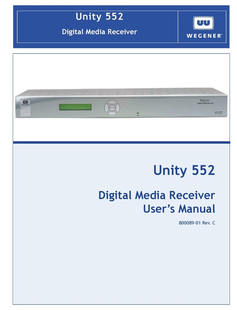
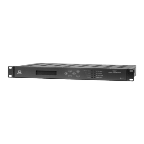
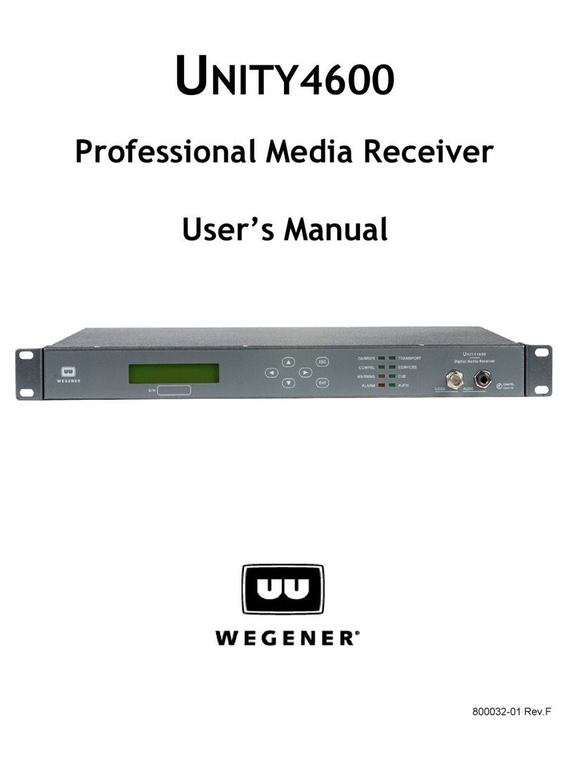
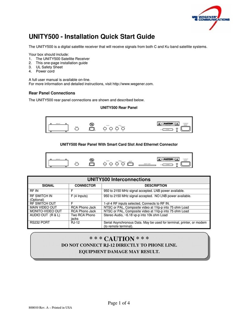
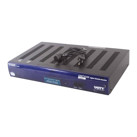
Wegener DR95 User manual

Instruction Manual
MODEL DR95/DR96
DIGITAL AUDIO SCPC RECEIVER
Data, drawings, and other material
contained herein are proprietary to
Wegener Communications, Inc., and
may not be reproduced or duplicated in
any form without the prior permission of
Wegener Communications, Inc.
When ordering parts from Wegener
Communications, Inc., be sure to include
the equipment model number, equipment
serial number, and a description of the part.
In all correspondence with Wegener
Communications, Inc., regarding this
publication, please refer to
DR95-/DR96-001C.
First edition: December 1995
Revised: June 1998
WEGENER
COMMUNICATIONS
R
TECHNOLOGY PARK / JOHNS CREEK
11350 TECHNOLOGY CIRCLE
DULUTH, GEORGIA 30097-1502
(770) 814-4000 FAX (770) 623-0698

DR95/DR96-001 ii
THIS PAGE INTENTIONALLY BLANK

iii DR95/DR96-001
CAUTION
RISK OF ELECTRIC SHOCK
DO NOT OPEN
CAUTION: TO REDUCE THE RISK OF ELECTRIC SHOCK,
DO NOT REMOVE COVER (OR BACK).
NO USER-SERVICEABLE PARTS INSIDE.
REFER SERVICING TO QUALIFIED SERVICE PERSONNEL.
CAUTION
As this unit is intended to interface with other electrical/electronic systems, proper
engineering practices must be adhered to during installation and check-out.
All AC power and ground must be installed in accordance with National Electric
Code Standards as to conductor size and limitations (see NFPA 70, articles 200-
280, as amended, if required), and lightning protection must be provided.
All RF interconnections must be properly shielded to prevent ingression or
egression of potential interfering sources to existing services.
Any damage to this unit caused by improper wiring/interconnections will void any
warranty extended.
The following warranty applies to all Wegener Communications products.
All Wegener Communications products are warranted against defective materials and workmanship for
a period of one year after shipment to customer. Wegener Communications' obligation under this
warranty is limited to repairing or, at Wegener Communications' option, replacing parts, subassemblies,
or entire assemblies. Wegener Communications shall not be liable for any special, indirect, or
consequential damages. This warranty does not cover parts or equipment which have been subject to
misuse, negligence, or accident by the customer during use. All shipping costs for warranty repairs will
be prepaid by the customer. There are no other warranties, express or implied, except as stated
herein.
WARRANTY
DR95/DR96-001 iv
THIS PAGE INTENTIONALLY BLANK

v DR95/DR96-001
TABLE OF CONTENTS
SECTION 1
GENERAL INFORMATION
Paragraph Page
1.1 INTRODUCTION...........................................................................................1-1

DR95/DR96-001 vi
3.1 ACQUISITION MODES................................................................................3-1
3.1.1 Installation Mode...................................................................................3-1
3.1.2 Tracking Mode......................................................................................3-3
3.1.3 Fade Mode.............................................................................................3-3
3.1.4 Carrier Table Search Mode ...................................................................3-3
MODETS i.......................................................................................3-5 -3

vii DR95/DR96-001
APPENDIX A
TECHNICAL SPECIFICATIONS
APPENDIX B
TERMINAL COMMANDS
B-1 CONTROL COMMANDS ................................................................................B-1
B-2 REPORTING COMMANDS.............................................................................B-6
B-3 HELP COMMANDS .........................................................................................B-12
TABLE OF CONTENTS – Continued
LIST OF ILLUSTRATIONS
Figure Page
1-1 Addressable Digital Audio SCPC Transmit and Receive Systems....................1-2
2-1 Model DR95-1X Digital Audio SCPC Receiver, Front and Rear View............2-2
2-2 Model DR96-1X Digital Audio SCPC Receiver, Front and Rear View............2-3
2-3 DR95-1X/DR96-1X Serial Cables to Printer or Terminal.................................2-6
2-4 DR95-1X/DR96-1X Serial Cables to Computer................................................2-7
2-5 DR95-1X/DR96-1X Serial Cables to Telephone Modem..................................2-8
3-1 Acquisition Mode, DR95-1X/DR96-1X Digital Audio SCPC Receiver...........3-2
LIST OF TABLES
Table Title Page
1-1 DR95-1X/DR96-1X Applications Data Chart ...................................................1-2
2-1 Model DR95-1X/DR96-1X Digital Audio SCPC Receiver,
Interconnect Descriptions stems....................................................................2-5
2-2 Recommended LNB Converter Specifications ..................................................2-6
2-3 Demodulator Data Output, RS422.....................................................................2-8
2-4 Control Data, RS232, Connector Pin-Out.........................................................2-9
2-5 External MPEG Input, RS422, Connector Pin-Out............................................2-9
2-6 DIP Switch Settings and Their Functions ..........................................................2-13

DR95/DR96-001 viii
THIS PAGE INTENTIONALLY BLANK

DR95/DR96-001 1-1
SECTION 1
GENERAL INFORMATION
1.1 INTRODUCTION
The purpose of this manual is to describe the proper installation and operation of the Wegener
Communications Model DR95-1X and DR96-1X Digital Audio Single Channel Per Carrier
(SCPC) Receivers. The DR95-1X and DR96-1X receivers are used in satellite-based digital
audio broadcast networks to deliver audio and data to the receive locations (downlinks). For the
remainder of this manual, the DR95-1X and Model DR96-1X receivers will be referenced as the
Model DR95-1X/DR96-1X receivers except where the differences between the units are
described.
1.2 SYSTEM DESCRIPTION
The Wegener digital audio system is a broadcast audio system using the ISO MPEG compression
technique. At the transmit site (uplink) analog audio is applied to an MPEG encoder where it is
digitized, compressed, and multiplexed with auxiliary data. The auxiliary data is a packetized
data stream containing carrier identification “tags,” network control commands (in addressable
networks), and user data. The resultant aggregate data stream is forward error corrected (FEC)
using rate 1/2 coding. The data rate is dependent on the analog audio bandwidth and the selected
encoder mode of operation (refer to table 1-1 below). The data rate is not agile. However,
receivers in the network will follow the encoder automatically as it is changed between mono,
dual mono, and joint stereo modes of operation. After FEC encoding the data stream is BPSK
(bi-phase shift keyed) modulated and upconverted to the final satellite uplink frequency.
TABLE 1-1. DR95-1X/DR96-1X APPLICATIONS DATA CHART
Channel
Spacing
(kHz)
Data
Rate
Transponder
6dB Occupied
Bandwidth
(kHz)
160
240
320
480
640
200
300
400
600
800
64
96
128
192
256
Maximum
Control
Channel
Data Rate
(bps)
4800
4800
9600
9600
9600
Dual
Mono
8.2
10.5
10.5
20
20
Maximum Audio BW (kHz)
Mono
8.2
20
20
20
20
Joint
Stereo
8.2
12.5
20
20
20
*
* Recommended

DR95/DR96-001 1-2
At the receive site, a dish antenna recovers the signal and couples it to an LNB (low-noise block
downconverter). The LNB amplifies and downconverts it to L-band (950 to 1450 MHz). This L-
band signal is carried by coaxial cable (possibly through in-line amplifiers) to the DR95-
1X/DR96-1X. The DR95-1X/DR96-1X reverses the process described above thereby
reconstructing the original data and analog audio.
In an addressable network, the DR95-1X/DR96-1X is controlled by commands embedded in the
auxiliary data stream. These commands use a highly flexible addressing structure for targeting
commands and data to remote sites. All Wegener remote modules use a standard transmission
protocol which simplifies network expansion. Receive sites may be controlled individually, by
assigned group, or globally. Groups are defined at the uplink and receive sites may be assigned
to multiple groups.
Figure 1-1. Addressable Digital Audio SCPC Transmit and Receive Systems
WEGENER
COMMUNICA
TIONS
AUDIO
AMPLIFIER
L-Band
DR95 Digital
Audio Receiver
RECEIVE SYSTEM
Terminal, Serial Printer, or Phone Line Modem

DR95/DR96-001 1-3
1.3 EQUIPMENT DESCRIPTION
The Model DR95-1X Digital Audio SCPC Receiver is a complete L-Band Single Channel Per
Carrier (SCPC) receiver in a single compact desk top chassis. The Model DR96-1X Digital
Audio SCPC Receiver is packaged in a single 19” rack-mount unit. Both receivers consist of an
L-band tuner, BPSK data demodulator, 1/2rate FEC decoder, and ISO-MPEG audio decoder.
The DR95-1X/DR96-1X delivers CD quality mono, dual mono, or stereo program audio
channels together with an auxiliary data stream. The receiver may be controlled by Wegener’s
ANCS (Addressable Network Control System), or a dumb terminal through an RS-232 port on
the rear panel. Receiver status and link diagnostics are also accessed through the terminal.
The DR95-1X/DR96-1X is used for SCPC networks that require highly efficient, high-quality
digital audio in either mono or stereo formats. The SCPC technology allows multiple carriers to
access the satellite transponder from geographically different locations.
1.4 PART NUMBER DESCRIPTION
The diagram below illustrates how to construct the part number for a specific receiver
configuration. For example, the model number for a DR95-1X at 128 kbps, with a 115 VAC
power supply and U.S. line cord is DR95-1X-03-100. The model number for a similar DR96-1X
unit would be DR96-13-100.
D R 9 5 - 1 X - Y Y 0
Line Cord
0 U.S.
1 EURO
2 British
3 Australian
Data Rate (kbps)
164
296
3 128
4 192
5 256
Power Supply
1 115 VAC
2 230 VAC
Version of
MPEG Decoder
Second
1

DR95/DR96-001 1-4
1.5 RECEIVER FIRMWARE VERSION NUMBER
The receiver firmware version number is displayed to an ASCII terminal at receiver power-up.
Connect the terminal per paragraph 2.3.4 and turn it on. Then power up the receiver. Its initial
message is the firmware version number followed by its command prompt.
1.6 TECHNICAL SUPPORT
In the event the product fails to perform as described, contact Wegener Communications
Customer Service at (770) 814-4057.
To return a product for service:
1. Obtain a Return Material Authorization (RMA) by contacting Customer Service at
2. Plainly write the RMA number on the outside of the product shipping container.
3. Return the product, freight prepaid, to the address below.
Service Department RMA #_______
Wegener Communications, Inc.
11350 Technology Circle
Duluth, GA 30097-1502
Notice :
All returned material must be shipped freight prepaid. C.O.D. shipments will not be accepted.
Please contact the Wegener Communications Customer Service Department at the number above
if you have any questions regarding service procedures.

2-1 DR95/DR96-001
SECTION 2
INSTALLATION
This section contains information for setting up a receiving system which uses the Model
DR95-1X/DR96-1X Digital Audio SCPC Receiver. It is presumed that the Configuration Sheet
for the receiver is available. This document shows all the defaults programmed into the receivers’
non-volatile memory at the factory. Also, it is assumed that an appropriate antenna system has
been installed and pointed with the correct polarization. The control and monitoring scheme to be
used with the receiver should also be known, so it may be necessary to review OPERATIONS
section 3. Concept views of the possible system connections for the DR95-1X/DR96-1X receiver
are shown in figure 2-1 and 2-2, respectively, and a summary of all input and output connections
is given in table 2-1.
PLEASE READ THE FOLLOWING BEFORE ATTEMPTING TO
INSTALL THIS RECEIVER...
1) This manual does not specify the system design from the LNB through cabling and line
amplifiers to the receiver. Good engineering practice should be observed to avoid overload of a
line amplifier or loss of signal-to-noise ratio in a long RF cable run. Where customers lack in-
house systems engineering expertise, they may contact Wegener Sales at (770) 623-0096 about
turnkey system design services.
2) The satellite receiving antenna system should meet the requirements specified by the program
originator for gain and noise temperature. The antenna should have been aligned using some
other suitable receiving device or spectrum analyzer. This will include correctly aiming the
antenna toward the source satellite, and rotating the polarization adjustment for reception from
the desired transponder.
3) The phase stability of the LNB converter’s local oscillator (LO) must meet the requirements
given in table 2-2 for adequate DR95-1X/DR96-1X receiver performance. Frequency stability of
the converter’s LO when subjected to vibration (as from wind) is also a concern. It is strongly
recommended that, at least for 64KB/S services, the converter’s LO should be stabilized by a
phase-lock-loop to an internal crystal-oscillator reference. Contact Wegener Communications
Sales Department at (770) 623-0096 for a list of preferred LNB converters for your application.
4) The DR95-1X/DR96-1X supplies DC power for an LNB (and perhaps line amplifiers) on the
center-conductor of its RF input. Refer to table 2-1 for its loading specification. Although that
DC output has a self-resetting 0.5 amp fuse, the receiver cannot function during overcurrents
caused by connection to an incompatible device. Note that this DC power may be disconnected
using an internal jumper. Contact Wegener Communications Customer Service Department.
5) After the receiver has been installed and has initially acquired its first valid carrier, it may be
possible to use its link monitoring capability to further optimize antenna pointing. Please refer to
OPERATIONS section 3 before doing so. Use caution in adjusting antenna pointing, because if
too coarse an antenna adjustment is made, loss of signal (and signal tracking) may result. This
would compel the installer to coarsely re-point the antenna using a separate receiving device.

DR95/DR96-001 2-2
Figure 2-1. Model DR95-1X Digital Audio SCPC Receiver, Front and Rear View
RESET
BREAKER
8
RF INPUT
LNB DC OUT
1
RS-422
DATA OUT
DEMOD
50 WATTS
50/60 Hz
115VAC
230VAC
GROUND
CHASSIS
DO NOT OPEN
RISK OF ELECTRIC SHOCK
AUDIO
SERV 1
SERV 2
CONTACT RATING 0.1A @ 30VDC
GND
AGC
OPT1
OPT2
ALARM
-
-
+
+
2
GND
1
GND
SERV
AUDIO
SERV
SERVICE 2
COMMUNICATIONS
WEGENER
SERVICE 1SIGNAL
CHANNEL SELECTCHANNEL
SEEK AGCSTATUS
REAR VIEW
FRONT VIEW
MODE
EXT MPEG IN
Terminal, Serial Printer, or
Modem L-band
950 - 1450 MHz

2-3 DR95/DR96-001
Figure 2-2. Model DR96-1X Digital Audio SCPC Receiver, Front and Rear View
* * * WARNING * * *
When connecting cables to “F” type connectors, apply no more than 12 inch lbs.
Avoid connecting adapters directly to “F” type connectors. Use at minimum a one
foot flexible extension cable between “F” type connectors and adapters.
Model DR96
Digital Audio Receiver
STATUS SEEK AGC MARGIN SERVICE 1
COMMUNICATIONS
MUTE
SERVICE 2
WEGENER
Status
Indicator
Seek
Indicator
AGC
Warning
Margin
Warning
Indicator
Service 1
Mute
Indicator
Service 2
Mute
Indicator
Front View
EXT MPEG IN
MODE
AES EBU
DIGITAL AUDIO
OPT1
AUDIO
SERV
GND
+
-
+
SERV
1
AGC
ALARM
GND
-
2
AUDIO SERV 1
SERV 2
OPT2
GND
RF INPUT
AVIS:
RS-232
CTRL DATA
RS-422
DEMOD
DATA OUT
18 LNB DC OUT
RISK OF ELECTRIC SHOCK
DO NOT OPEN
RISQUE DE CHOC ELECTRIQUE NE PAS OUVRIR
GROUND
CHASSIS
RESET
BREAKER 50/60 Hz
0.15/0.08 A
115/230 VAC
AUXILIARY RELAYS
K
41
KK
23
KK
75
KK
6K
8K
915
K
11
K
10
K12
K14
K
13
K16
K
Optional Relay Board L-band
950-1450 MHz
Terminal, Serial Printer,
or Modem
Rear View

DR95/DR96-001 2-4
THIS PAGE INTENTIONALLY BLANK

2-5 DR95/DR96-001
TABLE 2-1. MODEL DR95-1X/DR96-1X DIGITAL AUDIO SCPC RECEIVER,
INTERCONNECT DESCRIPTIONS
Connector
Signal Type Description
RF INPUT F-coax, female 950 to 1450 MHz signal band from LNB.
+15 to +24 VDC @ 350 mA to LNB, may be
disconnected using internal jumper.
DATA OUT, RS422 RJ-45 phone MPEG-compressed digital audio data, RS422
jack (refer to table 2-3 for pinouts)
CONTROL DATA, DB9, female Serial port, RS232 (refer to table 2-4 for
RS232 pinouts)
SERVICE 1 RCA phono Unbalanced audio monitor, high impedance
AUDIO
SERVICE 2 RCA phono Unbalanced audio monitor, high impedance
AUDIO
SERVICE 1 Terminal strip Balanced audio, 600 ohm impedance
AUDIO (+, GND, –)
SERVICE 2 Terminal strip Balanced audio, 600 ohm impedance
AUDIO (+, GND, –)
EXT MPEG INPUT RJ-45 phone jack External MPEG compressed digital audio data
input, RS-422 (refer to table 2-5 for pinouts)
ALARM Terminal strip Receiver alarm contacts, rated @ 30 VDC,
0.5A, jumper programmable to be either N.C. or
N.O. in non-alarm state (which is energized
state).
AGC Terminal strip Signal level indication, more voltage indicating
stronger signal, range about +4 to +8 VDC.
OPT1 Terminal strip Option, to be defined
OPT2 Terminal strip Option, to be defined

DR95/DR96-001 2-6
TABLE 2-2. RECOMMENDED LNB CONVERTER SPECIFICATIONS
Characteristic Specification
Frequency Stability (prod.
tolerance, temperature,
aging, etc.)
SSB Phase Noise (max)
±1 MHz
Offset dBc/Hz
10 kHz –75
100 kHz –85
D95-1X/DR96-1X DB9 (DCE)
(MALE) (MALE)
PIN SIGNAL INTERCONNECTION SIGNAL PIN
8 WIRE OPTION
4 WIRE OPTION
9
3
2
7
8
6
5
1
4
22
2
3
4
5
6
7
8
20
2
5
4
6
1
8
3
9
7
RI
TX
RX
RTS
CTS
DSR
GND
DCD
DTR
RI
TX
RX
RTS
CTS
DSR
GND
DCD
DTR
RX
GND
DTR
DSR
DCD
CTS
TX
RI
RTS
RX
GND
DTR
DSR
DCD
CTS
TX
RI
RTS
3
7
20
6
8
5
2
22
4
ASCII TERMINAL OR
SERIAL PRINTER DB25 (DTE)
NOT CONNECTED
NOT CONNECTED
NOT CONNECTED
NOT CONNECTED
NOT CONNECTED
NOT CONNECTED
Figure 2-3. DR95-1X/DR96-1X Serial Cables to Printer or Terminal

2-7 DR95/DR96-001
COMPUTER DB9 (DTE)
(FEMALE)
PIN SIGNAL INTERCONNECTION SIGNAL PIN
8 WIRE OPTION
5 WIRE OPTION
9
3
2
7
8
6
5
1
4
9
3
2
7
8
6
5
1
4
2
5
4
6
1
8
3
9
7
2
5
4
6
1
8
3
9
7
RI
TX
RX
RTS
CTS
DSR
GND
DCD
DTR
RI
TX
RX
RTS
CTS
DSR
GND
DCD
DTR
RX
GND
DTR
DSR
DCD
CTS
TX
RI
RTS
RX
GND
DTR
DSR
DCD
CTS
TX
RI
RTS
NO CONNECTION
NO CONNECTION
NO CONNECTION
NO CONNECTION
NO CONNECTION
D95-1X/DR96-1X DB9 (DCE)
(MALE)
Figure 2-4. DR95-1X/DR96-1X Serial Cables to Computer

DR95/DR96-001 2-8
AUTO MODEM DB25 (DCE)
(MALE)
PIN SIGNAL SIGNAL PIN
5
2
3
8
7
6
4
9
1
7
2
3
4
5
20
6
GND
RX
TX
CTS
RTS
DSR
DTR
RI
DCD
GND
TX
RX
RTS
CTS
DTR
DSR
DR95-1X/DR96-1X SERIAL CABLES TO
TELEPHONE MODEM
22
RI
DCD 8
NO CONNECTION
NO CONNECTION
D95-1X/DR96-1X DB9 (DCE)
(MALE)
Figure 2-5. DR95-1X/DR96-1X Serial Cables to Telephone Modem
TABLE 2-3. DEMODULATOR DATA OUTPUT, RS422
(Synchronous timing per RS449)
Pin Signal Description
1 Ground
2 Data-A RS422 Ckt-A of MPEG-compressed data.
3 Data-B RS422 Ckt-B of MPEG-compressed data
4 RR-A RS422 Ckt-A of “Receiver Ready,” low with respect
to Ckt-B if receiver is in alarm state.
5 RR-B RS422 Ckt-B of “Receiver Ready” (see above).
6 Clock-A RS422 Ckt-A of sync clock, transitions low-to-high
with respect to Ckt-B at data bit transition.
7 Clock-B RS422 Ckt-B of sync clock (see above).
This manual suits for next models
1
Table of contents
Other Wegener Receiver manuals

Wegener
Wegener UNITY4600 User manual

Wegener
Wegener Unity 4650 User manual

Wegener
Wegener unity 500 User manual

Wegener
Wegener UNITY 4600 User manual

Wegener
Wegener Unity 552 User manual

Wegener
Wegener UNITY500 Datasheet

Wegener
Wegener muzak FM2 1999 User manual

Wegener
Wegener UNITY 4600 User manual

Wegener
Wegener UNITY 550 Datasheet

Wegener
Wegener unity 500 Datasheet