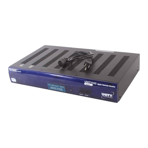
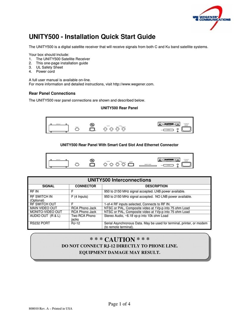
Wegener unity 500 User manual

800001-01 Rev. E
UNITY500
Enterprise Media Receiver
User’s Manual

UNITY 500 USER’S MANUAL
800001-01 Rev. E ii www.wegener.com
A proven world leader in digital video, audio & broadcast data systems, WEGENER’s
management system is certified to ISO 9001:2000.
Data, drawings, and other material contained herein are proprietary to Wegener Com-
munications, Inc., and may not be reproduced or duplicated in any form without the prior
written permission of Wegener Communications, Inc.
The information contained herein is subject to change without notice. Revisions may be
issued to advise of such changes and/or additions.
2005 Wegener Communications, Inc. All rights reserved.
WEGENER, COMPEL CONTROL, and UNITY 500 are trademarks of WEGENER
Comunications, Inc. All other trademarks are the property of their respective owners.
Correspondence regarding this publication,
800001-01 Revision E
Fifth Edition: April 2005
should be forwarded to:
Wegener Communications, Inc.
Technology Park/Johns Creek
11350 Technology Circle
Duluth, GA 30097-1502
Phone: 770-814-4000
Fax: 770-623-0698
The Wegener Unity 500 is approved under FCC Part 15B Class A, UL/C-UL1950 3rd Edition,
and CE [EN60950, EN55022(94), and EN55024(98)].

UNITY 500 USER’S MANUAL
www.wegener.com iii 800001-01 Rev. E
TABLE OF CONTENTS
CHAPTER 1. GENERAL INFORMATION ...................................................................................................... 1
1.1. Manual Overview ........................................................................................................ 1
1.1. Unity 500 Product Overview........................................................................................ 1
1.1.1. The Unity 500 digital Television Receiver........................................................ 1
1.1.2. Unity 500 Features and Options...................................................................... 2
1.1.3. COMPEL™ Network Control........................................................................... 2
1.2. Unity 500 Product Specifications ................................................................................. 2
1.3. Safety Summary.......................................................................................................... 5
CHAPTER 2. INSTALLATION....................................................................................................................... 7
2.1. Unpacking and Inspection........................................................................................... 7
2.2. Location and Mounting................................................................................................ 7
2.2.1. FCC-Mandated Suppression of Radio Frequency Emissions........................... 7
2.2.2. Rack Mounting................................................................................................ 8
2.2.3. Desktop Installation......................................................................................... 8
2.3. Rear Panel Connections ............................................................................................. 9
Smart Card.................................................................................................................. 9
CHAPTER 3. OPERATION ......................................................................................................................... 11
3.1. General..................................................................................................................... 11
3.2. Front Panel Controls And Indicators .......................................................................... 11
3.3. LED Status and Alarm/Warning Conditions................................................................ 11
3.4. Power-On Procedure................................................................................................. 13
3.5. On-Screen Network E-mail........................................................................................ 13
3.6. On-Screen Display (OSD)......................................................................................... 13
3.7. Customizing and Viewing Settings for Your System................................................... 14
3.7.1. COMPEL™ System Control.......................................................................... 14
3.7.2. On-Screen Display (OSD) Settings ............................................................... 15
3.7.3. Edit Settings ................................................................................................. 15
3.7.4. Carrier Status ............................................................................................... 16
3.7.5. Carrier Select................................................................................................ 16
3.7.6. Signal Strength............................................................................................. 17
3.7.7. Serial Port Select.......................................................................................... 18
3.7.8. Audio Settings .............................................................................................. 18
3.7.9. Software Versions......................................................................................... 19
3.7.10. Data PIDS Settings....................................................................................... 20
3.8. Universal European Single User LNB ........................................................................ 21
CHAPTER 4. SEARCH FUNCTIONS.......................................................................................................... 23
4.1. Perms/Temps/Searching & Settings .......................................................................... 23
4.2. Settings Table (or Search Table)............................................................................... 24
4.3. Acquisition Modes..................................................................................................... 24
4.4. Acquisition Sub-Modes.............................................................................................. 26
4.5. Signal Quality Monitoring........................................................................................... 27
4.6. Frequency Tagging ................................................................................................... 27
UNITY 500 USER’S MANUAL
800001-01 Rev. E iv www.wegener.com
4.6.1. General Rules...............................................................................................27
CHAPTER 5. CUSTOMER SERVICE...........................................................................................................29
5.1. Warranty ...................................................................................................................29
5.2. Technical Support......................................................................................................29
APPENDIX A: TERMINAL/MODEM MODE ................................................................................................31
A.1 Terminal/Modem Commands.....................................................................................31
A.1.1 Network-Enabled Local Control Commands...................................................31
A.1.2 Local Control Commands ..............................................................................34
A.2 Reports .....................................................................................................................35
A.2.1 Carrier Status (Tracking) ...............................................................................35
A.2.2 Carrier Status (Not Tracking).........................................................................37
A.2.3 Parameters...................................................................................................38
A.2.4 Group Status.................................................................................................38
A.2.5 Network Controller Status..............................................................................40
A.2.6 MPEG Status ................................................................................................41
A.2.7 Settings Status..............................................................................................42
A.2.8 Settings Table ...............................................................................................42
APPENDIX B: RMA REQUEST FORM......................................................................................................45

UNITY 500 USER’S MANUAL
www.wegener.com v800001-01 Rev. E
LIST OF FIGURES
Figure 2.1: UNITY 500 Rear Panel..................................................................................... 9
Figure 2.2: U500 Rear Panel with Smart Card Slot and Ethernet Connector................... 9
Figure 3.1: Unity 500 Front Panel.................................................................................... 11
Figure 3.3: Unity 500 Terminal Main Menu Screen......................................................... 15
Figure 3.4: Unity 500 Terminal Carrier Status Screen.................................................... 16
Figure 3.5: Unity 500 Terminal Carrier Select Screen.................................................... 16
Figure 3.6: Unity 500 Terminal Signal Strength Screen ................................................. 17
Figure 3.7: Unity 500 Terminal Serial Port Select Screen.............................................. 18
Figure 3.8: Unity 500 Terminal Audio Settings Screen................................................... 19
Figure 3.9: Unity 500 Terminal Software Version/Serial No. Screen.............................. 19
Figure 3.10: Unity 500 Data PIDS Settings Screen......................................................... 20
Figure 4.1: Acquisition Modes......................................................................................... 24
Figure 4.2: Acquisition Sub-Modes................................................................................. 26
Figure A.1: Sample Unity 500 Carrier Status (Tracking) Report .................................... 35
Figure A.2: Sample Unity 500 Carrier Status (Not Tracking) Report ............................. 37
Figure A.3 Sample Unity 500 Parameters Report ........................................................... 38
Figure A.4: Sample Unity 500 Group Status Report....................................................... 38
Figure A.5: Sample Unity 500 Parameters Report.......................................................... 40
Figure A.6: Sample Unity 500 MPEG Status Report....................................................... 41
Figure A.7: Sample Unity 500 Settings Status Report.................................................... 42
Figure A.8: Sample Unity 500 Settings Table Report (Without Labels) ......................... 43
Figure A.9: Sample Unity 500 Settings Table Report (With Labels) .............................. 44

UNITY 500 USER’S MANUAL
800001-01 Rev. E vi www.wegener.com
LIST OF TABLES
Table 1.1: Unity 500 Technical Specifications ..................................................................2
Table 2.1: UNITY 500 Interconnect Descriptions..............................................................9
Table 2.2: UNITY 500 Serial Cables to Terminal or Printer .............................................10
Table 3.1: Unity 500 Front Panel Controls and Indicator LED........................................11
Table 3.2: Unity 500 Status LED Indications...................................................................12
Table 3.3: Unity 500 On-Screen Display (OSD) Fields....................................................14
Table 4.1. Settings Parameters for the UNITY500...........................................................23
Table 4.2. UNITY500 Settings Groups.............................................................................23
Table 4.3. Acquisition Mode Behavior.............................................................................25
Table 4.4: Signal Quality Information..............................................................................27
Table A.1: Unity 500 Network-Enabled Local Control Commands.................................31
Table A.2: Unity 500 Local Control Commands..............................................................34
Table A.3: Terms Used in U500 Carrier Status (Tracking) Reports.................................36
Table A.4: Terms Used in U500 Carrier Status (Not Tracking) Reports..........................37
Table A.5: Terms Used in Unity 500 Parameters Reports ..............................................38
Table A.6: Terms Used in U500 Group Status Reports..................................................39
Table A.7: Terms Used in U500 Network Control Status Reports..................................40
Table A.8: Terms Used in U500 MPEG Status Reports...................................................41
Table A.9: Terms Used in U500 Settings Status Reports...............................................42
Table A.10: Terms Used in U500 Settings Table Reports...............................................44

UNITY 500 USER’S MANUAL
www.wegener.com 1800001-01 Rev. E
Chapter 1. GENERAL INFORMATION
1.1. Manual Overview
This manual provides instructions and reference information for the proper installation
and operation of the Wegener Unity 500, referred to throughout the manual as the U500.
The manual is divided into the following chapters:
1. General Information – A description of the Unity 500, its functions and specifications,
and a glossary of terms
2. Installation – Procedures and information for the correct and safe installation of the
Unity 5000
3. Operation – Instructions on starting and operating the Unity 500
4. Maintenance – Information on maintaining the Unity 500 and resolving potential
operating difficulties
5. Customer Service – Our warranty and information about obtaining help.
An Index of keywords is also provided to help you quickly locate needed information.
Please email any suggestions or comments concerning this manual to
[email protected]. If you prefer to post through the mail, please send your
comments to the address below. If you have substantial or complex changes to
recommend, our preference is that you copy the page(s) in question, mark your changes
on that copy, and fax or mail us the copy. We always appreciate constructive criticism.
Our Address:
Attn: Manuals
Wegener Communications, Inc.
Technology Park / Johns Creek
11350 Technology Circle
Duluth, GA 30097-1502
Our Fax Number: (770) 497-0411
1.1. Unity 500 Product Overview
1.1.1. The Unity 500 digital Television Receiver
The Unity 500 Digital Television Receiver is a high-performance satellite Integrated
Receiver-Decoder (IRD) designed to meet the needs of the private television market-place.
Supporting both the PAL and NTSC video standards, the Unity 500 is uniquely positioned
to provide high-quality video, audio, and data to demanding customers. The Unity 500
supports DVB World Standard Teletext and Line 21 Closed Captioning and Extended
Data for enhanced video functionality.
Multiple data features are standard to provide additional ways to use spare digital
spectrum for revenue and operational control. A 38.4-kbps asynchronous output provides
constant streaming of control and user information. This data port is used for local and
remote diagnostics, COMPEL™ data delivery services, and auxiliary data. Using
COMPEL, the data output can control external devices, such as collection encoding
systems and video switching equipment. COMPEL is able to command the serial number
to be displayed on screen for asset protection.

UNITY 500 USER’S MANUAL
800001-01 Rev. E 2www.wegener.com
1.1.2. Unity 500 Features and Options
The Unity 500 utilizes and supports the following standards:
•MPEG-2/DVB Compliant.
•1.5Mb – 50 Mbps Transport Rate.
•1.08 – 45 Msps Symbol Rate.
•SCPC and MCPC.
•RS-232 Asynch Data up to 38.4 Kbps.
•Line 21 Closed Captioning and Extended Data.
•World Standard Teletext.
•On-Screen Control.
The Unity 500 has integral support for the following COMPEL™features:
•COMPEL™ Network Control.
•COMPEL™ CA and Wegener PIN Scrambling.
•COMPEL™ On-Screen E-Mail.
The Unity 500 also provides the following options:
•Optional Rack Mounting brackets.
•Optional Four-Port RF Switch
1.1.3. COMPEL™ Network Control
COMPEL gives you the power to manage a network of Unity 500s and other Unity IRDs
with unparalleled functionality. With its unique network management features, such as
grouping, receiver control and scheduling, the operator can command individual groups
of receivers to switch, tune, or “output” video or data targeted specifically for that one
receiver or group of receivers. In addition, COMPEL is able to switch the Unity 500
between satellite transponders — even to a different satellite — for unequalled disaster
recovery.
1.2. Unity 500 Product Specifications
Table 1.1: Unity 500 Technical Specifications
Characteristic Specification
RF Input
Input Frequency Range 950.00 – 2150.00 MHz
Input Level Range -25 dBm total signal power down to –135 dBm/Hz
signal power spectral density (-25 to –65dBm)

UNITY 500 USER’S MANUAL
www.wegener.com 3800001-01 Rev. E
Characteristic Specification
Maximum Aggregate Input Power -5 dBm at max input signal
Input Impedance 75 ohms, unbalanced
Input VSWR <2.5:1
Input Noise Figure 8 dBm MAX at minimum input level
L.O. Leakage at Input [- 55 dBm
Demodulator/FEC Convert Symbol rate Fs to Transport Rate Ft by:
(2R*Fs)*(188/204)=Ft, where ‘R’ is the inner FEC
code ratio, either R = 1/2, 2/3, 3/4, 5/6, or 7/8.
Max Symbol-rate 30 Msps
Aggregate MPEG Transport
Rate 2.500 to 50.000 Mbps (limited by max symbol-rate
and inner FEC chosen), defined for 188-byte MPEG
transport packets.
Max Eb/No @ Video Threshold Depends on inner FEC:
1/2: 4.5 dB; 2/3: 5.0 dB; 3/4: 5.5 dB;
5/6: 6.0 dB; 7/8: 6.4 dB.
Compression System MPEG-2
Analog Output Formats NTSC or PAL
Supported Digital Video
Resolutions NTSC: 720Hx480V, 544Hx480V, 480Hx480V,
352Hx480V, 352Hx240V
PAL: 704Hx576V, 544Hx576V, 480Hx576V,
352Hx576V, 352Hx288V
Supported Chrominance
Sampling 4:2:0
Video Output All Video Output specs are for NTSC and PAL
Output Level 1.0 Vp-p, < +/- 5.5 %
Output Impedance 75 ohms
Multiburst From 0.5 to 4.2 MHz, < +0/-3dB
Differential Gain < 3%
Differential Phase < 3 Degrees
Line Time and Field Time
W-form Distortion < 2% p-p
Audio Decoder
Compression System MPEG-1 Layer 2
Sample Rates Supported 44.1 and 48 kHz
Unbalanced Audio Output Measured at 256 kbps audio PES rate, dual mono
mode
Output Level Adjust Range 0 to –14 dB attenuation from above output level.
Output Level – MAX PPL +9.0 +/- 0.5 dBu, 0 dB level, RCA Phono Jack
Impedance Unbalanced: < 1000 ohms

UNITY 500 USER’S MANUAL
800001-01 Rev. E 4www.wegener.com
Characteristic Specification
Audio Parameters
Frequency Response 20 Hz to 20 kHz, +0.5/-2.0 dB
Harmonic Distortion (1 kHz
test tone, 1 dB below PPL) < 0.5%
S/N Ratio < 68 dB (22 Hz to 20 KHz) unweighted
Dynamic Range 16 Bits
A/V Sync < +/- 50 ms error
Serial Ports
RS-232 RJ12
Selectable Services Auxiliary character-based async output
E-mail character-based async output
Terminal monitoring and control
Baud Rates 9.6 kbps and 19.2 kbps
Formatting 8 data bits; 1 start, 1 stop; half-duplex.
Input Power Rating 115/230 VAC, 0.8/0.5A, 50/60Hz
LNB DC Power Universal LNB supported
Voltage 14 or 19 VDC, for LNB polarity selection
22 kHz tone 22 kHz control tone, for LNB DRO selection
Current 250 mA max
Short-circuit protection Foldback regulator
AC Power Input
Voltage 115/230 VAC auto-detect/selected
Frequency 50 or 60 Hz +/- 2%
Power Consumption 30 watts with full LNB load
Operating Environment
Operating Temperature Range +10° to +40° C in still air with unblocked vents
Storage Temperature Range -20° to + 60° C
Operating Humidity Maximum relative humidity 80% for temperatures up
to 31° C, decreasing linearly to 50% relative humidity
at 40° C.
Maximum Operating Elevation 6560 Ft (2000M) above sea level

UNITY 500 USER’S MANUAL
www.wegener.com 5800001-01 Rev. E
1.3. Safety Summary
The Unity 500 is designed for safe use with few special precautions required of the user.
The following items are basic precautions to use when installing and working with the
Unity 500 unit:
Do not open the Unity 500's chassis cover.
The Unity 500 incorporates security labels over some of the screws. There are no user-
serviceable components within the IRD. Tampering with the security labels, or opening
the unit, will void your warranty. If you have questions, contact the Wegener Customer
Support Department at the address or phone (fax) numbers listed in Chapter 5, Customer
Service, of this manual.

UNITY 500 USER’S MANUAL
800001-01 Rev. E 6www.wegener.com
This page intentionally left blank.

UNITY 500 USER’S MANUAL
www.wegener.com 7800001-01 Rev. E
Chapter 2. INSTALLATION
This chapter provides instructions on unpacking, mounting, and connecting your U500 as
well as connector information including detailed pinouts.
2.1. Unpacking and Inspection
Carefully unpack the unit and its ac power cord and inspect for obvious signs of physical
damage that might have occurred during shipment. Any damage claims must be reported
to the carrier immediately. Be sure to check the package contents carefully for important
documents and materials.
NOTE: Please save the packing materials and original shipping containers in case you
must later return the unit for repair. Packing these units in other containers in
such a way that they are damaged will void your warranty.
2.2. Location and Mounting
The U500 may be mounted in a standard 19-inch equipment rack or set up for desktop
operation. In either location, maintain a clean, dry environment for the U500.
2.2.1. FCC-Mandated Suppression of Radio Frequency Emissions
WARNING
This is a Class A product. In a domestic environment this product may cause radio
interference for which the user may need to take mitigating action.
If the Ethernet port has a cable connected to it, that cable must be properly shielded and
grounded to minimize RF emissions that could interfere with nearby equipment.
DANGER
To avoid damage to the U500 unit and other equipment, or personal injury, the following
items should be strictly observed.
2.2.1.1. Elevated Ambient Operating Temperatures in Rack-Mounted Units
When equipment is installed in a closed or multi-unit rack assembly, the ambient
operating temperature of the rack environment may be greater than the room’s ambient
temperature. Therefore, consideration should be given to the ambient air temperature
within the rack (not just inside the room) when deciding if the maximum recommended
ambient operating temperature (TMRA) is met or exceeded.
2.2.1.2. Reduced Air Flow
Equipment should be installed such that the airflow required for safe operation of the
equipment is not compromised. The U500 may be arranged in a rack without empty
spaces between units, if heat buildup is prevented by ensuring that the side vents remain
unblocked, and that there is adequate clearance around the vent holes.
2.2.1.3. Mechanical Loading
Rack-mounted equipment should be installed in such a way that a hazardous condition is
not produced by uneven loading. The U500 unit is not very heavy, but total rack loading
must be considered. Also, do not rest any unsupported equipment on a rack-mounted
U500 unit.

UNITY 500 USER’S MANUAL
800001-01 Rev. E 8www.wegener.com
2.2.1.4. Circuit Overloading
Consideration should be given to the connection of the equipment to the supply circuit
and the effect that overloading of circuits could have on overcurrent protection and supply
wiring. Ensure that the total rack or breaker power consumption does not exceed the
limits of the AC branch circuit. Appropriate consideration of equipment ratings should be
used when addressing this concern.
2.2.1.5. Reliable Earthing
Reliable earthing of rack-mounted equipment should be maintained. Particular attention
should be given to supply connections other than direct connections to the branch circuit
(use of power strips, chassis ground lugs, etc.).
2.2.2. Rack Mounting
The U500 is sized as a single RU and will fit an EIA-standard, 19-inch-wide equipment
rack.
First install angle brackets or cross-supports capable of supporting both the unit and its
connecting cables. Screw or bolt the supports securely to the equipment rack.
Place the U500 on its supports and use four anchor screws or bolts and nuts to secure
the U500 front brackets to the rack.
The front brackets must be secured to the rack. If the front brackets are left unsecured,
the unit may shift forward and fall from the rack during installation or operation. Failure to
secure the front brackets may result in personal injury and/or damage to the equipment.
2.2.3. Desktop Installation
To set up the U500 in a desktop environment, place the U500 on a flat surface where it
will not be subject to spills or impacts. Also route cables to the unit so that they will not be
hit or pulled, causing damage to the connectors or to the unit itself. Ensure a sufficient
flow of cool air so that the unit's operating ambient temperaturerange is not exceeded.
(See 2.2.1.2, Reduced Air Flow, on page 11.)
Locate the U500 and its cables to avoid impacts, spills, and pulling cables and to ensure
sufficient air flow. Failure to locate the U500 in a proper environment may result in
damage to the equipment.

UNITY 500 USER’S MANUAL
www.wegener.com 9800001-01 Rev. E
2.3. Rear Panel Connections
The UNITY 500 rear panel connections are shown in Figures 2.1 and 2.2, and described in
Table 2.1 below.
Figure 2.1: UNITY 500 Rear Panel
Figure 2.2: U500 Rear Panel with Smart Card Slot and Ethernet Connector
2.3.1. Smart Card
The UNITY 500 may be equipped with a smart card slot and an Ethernet connector. The
slot for the smart card is installed for future encryption updating. It conforms to the ISO
7816 standard. It is not necessary to have the smart card installed for proper operation of
the UNITY 500, including COMPEL CA operation.
Table 2.1: UNITY 500 Interconnect Descriptions
Signal Connector Description
RF IN F950 to 2150 MHz signal accepted. LNB power available.
RF SWITCH IN F (4 Inputs) 950 to 2150 MHz signal accepted. NO LNB power available.
RF SWITCH OUT F1-of-4 RF inputs selected.
MAIN VIDEO OUT Phono Jack NTSC or PAL , Composite video at 1Vp-p
MONITOR-VIDEO OUT Phono Jack NTSC or PAL , Composite video at 1Vp-p
AUDIO OUT (R & L) Two phono jacks Audio stereo
RS232 PORT RJ-12 Serial Asynchronous Data. May be used for terminal, printer,
or modem (to remote terminal).
MODULE
RF IN
123456
S/N
AUDIO
RL
OUTOUT OUT
MAINVIDEO
MONITOR
OUT
RS232
1 6
115/230VAC
50/60Hz
0.8/0.5A
1 8
10/100
BASE T
SMART CARD
RISQUE DE CHOC ELECTRIQUE NE PAS OUVRIR
RISKOFELECTRICSHOCK
AVIS:
DONOTOPEN
MODULE
RF IN
123456
S/N
AUDIO
RL
OUTOUT OUT
MAINVIDEO
MONITOR
OUT
RS232
1
6
115/230VAC
50/60Hz
0.8/0.5A
RISQUE DE CHOC ELECTRIQUE NE PAS OUVRIR
RISK OF ELECTRIC SHOCK
AVIS
:
DO NOT OPEN

UNITY 500 USER’S MANUAL
800001-01 Rev. E 10 www.wegener.com
Table 2.2: UNITY 500 Serial Cables to Terminal or Printer
Unity 500: RJ-12 Computer: DB-9 (Female) ASCII Terminal or Serial
Printer: DB-25 (Male)
Pin Signal Pin Signal Pin Signal
1No Connection
2TX Data 2RX Data 3RX Data
3RX Data 3TX Data 2TX Data
4No Connection
5Ground 5Ground 7Ground
6RI 9RI 22 RI

UNITY 500 USER’S MANUAL
www.wegener.com 11 800001-01 Rev. E
Chapter 3. OPERATION
3.1. General
This section provides information and procedures for powering up and operating the unit.
The IRD can be controlled via COMPEL, local terminal, modem (remote terminal), and
On-Screen-Display push buttons. Normally, COMPEL is the primary method of controlling
the IRD, while the other control methods are supplemental. See Section 2.7.1. COMPEL
Control on page 19 for more information, and the COMPEL Manual for a complete
explanation of COMPEL controls.
3.2. Front Panel Controls and Indicators
The front panel indicators and controls are shown in Figure 3.1 and described in Table 3.1.
Figure 3.1: Unity 500 Front Panel
Table 3.1: Unity 500 Front Panel Controls and Indicator LED
Item Description
IRD Status See Table 3.3 (Page 12) for a description of the Status LED.
On-Screen- Display On-Screen-Display (OSD) of IRD may be activated by pressing the SELECT push-
button switch on the front panel. It is also automatically activated by certain IRD
status conditions, such as loss of signal.
SELECT Push button activates (OSD) and selects options displayed.
ENTER Push button enters options selected on OSD.
3.3. LED Status and Alarm/Warning Conditions
The Unity 500 unit's only LED is Red/Green, located on the front panel, and labeled
Status. Table 3.2, lists the behavior of the Status LED during Power Up and Normal
operation, as well as the color and blink/flutter pattern shown during various Warning and
Alarm conditions.
The conditions are listed in the order of their display priority with highest priority at the
top.
NOTE: The alarm conditions are those conditions preventing the delivery of video.
The following definitions of Amber, Flash, Blink, and Flutter explain the terms used in
The Status LED Display column of Table 3.2.
•Amber Red and Green turned ON at the same time.
•Flash ON for 100 ms, OFF for 100 ms.

UNITY 500 USER’S MANUAL
800001-01 Rev. E 12 www.wegener.com
•Flutter ON for 50 ms, OFF for 50 ms.
•Blink LED is OFF for 1 second, then blinks ON for 250 ms and OFF for 250 ms
between 1 and 12 times, according to the Alarm/Warning Code. Is then
OFF for 1 second, and blinks 1-12 times again. This pattern continues
until the alarm/warning condition is cleared. (For example, if the unit is
displaying a “header search mode” alarm, the LED will be OFF for 1 sec.,
then will blink (RED) ON for 250 ms and OFF for 250 ms five times. It will
then be OFF for 1 sec, followed by blinking 5 times, etc. The LED blinking
RED indicates an alarm, while AMBER indicates a warning.
Note: ms = 1/1000 second.
Table 3.2: Unity 500 Status LED Indications
Mode Condition Status LED Display
Power Up IRD is in process of powering up Amber flutter
Not Defined Red Blink w/ Count = 1
In Fade Mode < 5 seconds Red Blink w/ Count = 2
Installation Mode > 5 seconds Red Blink w/ Count = 3
Carrier Table Search Mode Red Blink w/ Count = 4
Header Search Mode Red Blink w/ Count = 5
Eb/No below alarm level (and locked on carrier) Red Blink w/ Count = 7
No MPEG Data (but locked on carrier) > 5 seconds Red Blink w/ Count = 8
Not Defined Red Blink w/ Count = 9
PID conflict on power up Red Blink w/ Count = 10
Not authorized for current program Red Blink w/ Count = 11
Alarm
Selected program not available Red Blink w/ Count = 12
Not Defined Amber Blink w/ Count = 1
Marginal Eb/No (and locked on carrier) Amber Blink w/ Count = 2
COMPEL Required and No COMPEL within last 2 minutes Amber Blink w/ Count = 3
Selected audio program not available Amber Blink w/ Count = 4
RF Level too LOW Amber Blink w/ Count = 5
RF Level too HIGH Amber Blink w/ Count = 6
Corrupt Code Amber Blink w/ Count = 7
No MPEG data < 5 seconds and locked on carrier Amber Blink w/ Count = 8
Fade or Installation Mode < 10 seconds Amber Blink w/ Count = 9
Warning
PID conflict due to PID change during normal operation Continuous Amber flutter
Normal Mode for a COMPEL-not-Required Unit Green
Addressed COMPEL within last 5 seconds Green Flutter
Normal
COMPEL within last 2 minutes Green

UNITY 500 USER’S MANUAL
www.wegener.com 13 800001-01 Rev. E
3.4. Power-On Procedure
Apply power to the IRD. The unit initializes various devices and configures itself
according to the EEPROM settings. It then waits for the receiver section to complete its
power up test, which takes about 10 seconds.
When the receiver section passes its test, the IRD sends a tune command and the
Welcome Banner screen to the serial port.(An example is shown in Figure 3.2 below.) If
the unit is in Terminal mode, the banner displays on the terminal screen. The IRD then
enters Alarm mode until all of the alarm conditions are cleared.
Figure 3.2: Unity 500 Terminal Welcome Banner Screen
Your banner may be different from this example depending on the options purchased.
NOTE: The “Type H…” text at the bottom of the screen is shown only if the serial device
is set to Terminal mode.
3.5. On-Screen Network E-mail
The network may, through the COMPEL network control system, send e-mail messages to
the video (OSD) screen. The content, location, and duration of the messages are
essentially under the control of the network. The local user may neither move nor scroll
through the messages. If necessary, a message may be cleared by the local user by:
1. Either power-cycling the unit,
2. Or pressing the SELECT button on the front panel to get a local control menu and
then exiting out of that menu.
[See Section 3.7.2 On-Screen Display (OSD) Settings on page 21.]
3.6. On-Screen Display (OSD)
The OSD information is contained in a 14-line x 40-character display in the video output
from the receiver. This output is viewed on a monitor connected to the video monitor
output of the receiver. Turn it on by pressing either the SELECT or ENTER push-button on
the front panel. Remove the display by selecting EXIT from the Main Menu. When a
menu is first shown, the cursor is always placed on its first action field (or action-with-edit
field, whichever is first).
The OSD provides the following:
1. Carrier Status,
2. Signal Strength Monitoring,
3. Serial Port device selection,
Wegener Communications Copyright 2000
Unity 500 Integrated Receiver Decoder
Application : V106
Boot : V102
Xilinx : CA600048-01 100
Secure : 600041 1.1
Tuner : L64724D
Type H for a list of terminal commands

UNITY 500 USER’S MANUAL
800001-01 Rev. E 14 www.wegener.com
4. Software Version, and
5. The ability to make changes to unit settings. See Section 3.7 (Page 14).
All menus are white text with a solid blue background. When highlighted, they show as
blue text on a white background. The cursor can be moved only to the fields listed below.
The function of each push button for each field type is described below.
Table 3.3: Unity 500 On-Screen Display (OSD) Fields
Field Type SELECT Button ENTER Button
Action Field Moves the cursor to the next Action Field
(or Action w/ Edit Field, whichever is
next). Wraps at end.
Takes action on the current field.
Action w/ Edit Field Same as for Action Field.Moves cursor to corresponding Edit Field.
Edit Field If the cursor is not on last digit within the
Edit Field, it moves the cursor to the next
digit. If the cursor is on the last digit, it
moves the cursor to the next Action Field
(or Action w/ Edit Field, whichever is next)
Increments current digit within Edit Field.
Wraps back to beginning after 9.
Edit Field w/ Choices Moves cursor to next Action Field (or
Action w/ Edit Field, whichever is next). Scrolls through list of choices. Wraps
back to beginning after the last item.
3.7. Customizing and Viewing Settings for Your System
Though the Unity 500 is set up at the factory, you can customize its settings to fit your
system using the OSD and front-panel push buttons. You may also view those settings
and various status and version fields from the front panel, viewing on a monitor.
Note: The screens shown in Section 3.7 contain only sample data. The actual data for
normal operation will differ due to settings differences for each network or unit.
3.7.1. COMPEL™ System Control
The Unity 500 IRD is most often controlled via the Wegener COMPEL Control System. This
system is managed at the uplink site, sending a control stream with the usual audio and
video data streams. The COMPEL System addresses units, and commands them to
perform various functions.
Among its functions is the ability to enable or limit aspects of local control. (See the
following section for more on this capability.) Also, COMPEL has the ability to mute the
audio and video of an IRD if it is inadvertently tuned to a frequency it is not authorized to
receive.
If an RF Switch option module is installed, COMPEL will control which of the four RF feeds
is being processed. For more information on this, see the COMPEL Manual, or contact
your service provider.
Other manuals for unity 500
1
Table of contents
Other Wegener Receiver manuals

Wegener
Wegener UNITY4650 User manual

Wegener
Wegener UNITY 550 Datasheet

Wegener
Wegener muzak FM2 1999 User manual

Wegener
Wegener UNITY 550 User manual

Wegener
Wegener DTV 720 Datasheet

Wegener
Wegener Unity 552 User manual

Wegener
Wegener UNITY500 Datasheet

Wegener
Wegener Unity 4650 User manual

Wegener
Wegener DR95 User manual

Wegener
Wegener unity 500 Datasheet