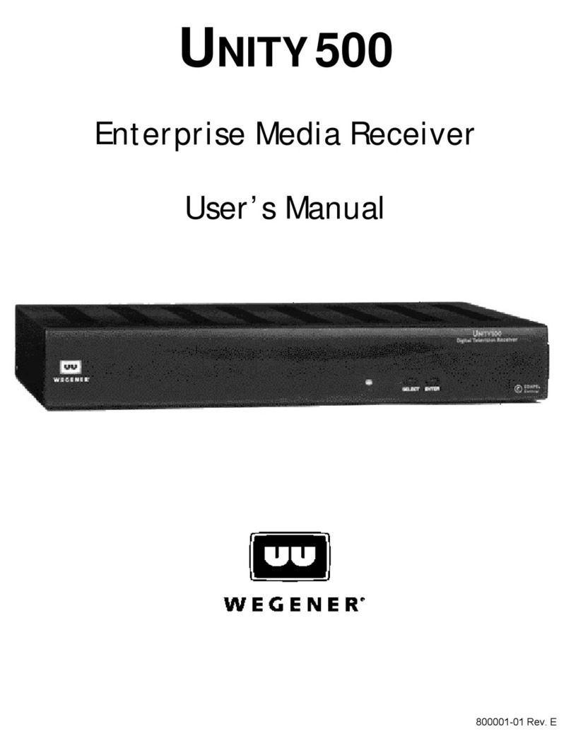
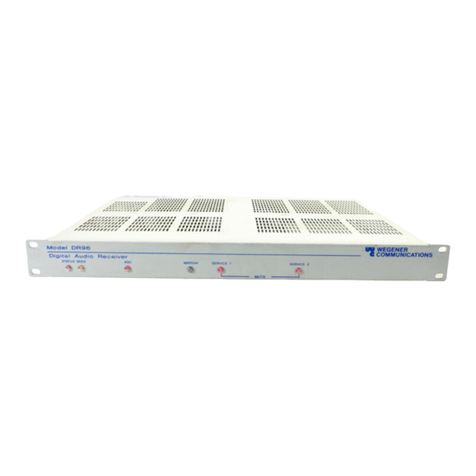
Wegener muzak FM2 1999 User manual

PRELIMINARY April 15, 1999
Instruction Manual
Model 1999
FM2®Addressable Satellite
Audio Receiver
Data, drawings, and other material
contained herein are proprietary to
Wegener Communications, Inc., and
may not be reproduced or duplicated in
any form without the prior permission of
Wegener Communications, Inc.
When ordering parts from Wegener
Communications, Inc., be sure to include
the equipment model number, equipment
serial number, and a description of the part.
In all correspondence with Wegener
Communications, Inc., regarding this
publication, please refer to 1999-001.
Preliminary Edition: April, 1999
WEGENER
COMMUNICATIONS
R
TECHNOLOGY PARK / JOHNS CREEK
11350 TECHNOLOGY CIRCLE
DULUTH, GEORGIA 30097-1502
(770) 814-4000 FAX (770) 623-0698

1999-001 2
CAUTION
RISK OF ELECTRIC
SHOCK
DO NOT OPEN
CAUTION: TO REDUCE THE RISK OF ELECTRIC SHOCK,
DO NOT REMOVE COVER (OR BACK).
NO USER-SERVICEABLE PARTS INSIDE.
REFER SERVICING TO QUALIFIED SERVICE PERSONNEL.
CAUTION
As this unit is intended to interface with other electrical/electronic systems,
proper engineering practices must be adhered to during installation and check-
out.
All AC power and ground must be installed in accordance with National Electric
Code Standards as to conductor size and limitations (see NFPA 70, articles 200-
280, as amended, if required), and lightning protection must be provided.
All RF interconnections must be properly shielded to prevent ingression or
egression of potential interfering sources to existing services.
Any damage to this unit caused by improper wiring/interconnections will void any
warranty extended.
The following warranty applies to all Wegener Communications products.
All Wegener Communications products are warranted against defective materials and workmanship
for a period of one year after shipment to customer. Wegener Communications' obligation under this
warranty is limited to repairing or, at Wegener Communications' option, replacing parts,
subassemblies, or entire assemblies. Wegener Communications shall not be liable for any special,
indirect, or consequential damages. This warranty does not cover parts or equipment which have
been subject to misuse, negligence, or accident by the customer during use. All shipping costs for
warranty repairs will be prepaid by the customer. There are no other warranties, express or implied,
except as stated herein.
WARRANTY

3 1999-001
Table of Contents
SECTION 1 - GENERAL INFORMATION
Paragraph Title Page
1.1 INTRODUCTION ................................................................................... 4
1.2 PURPOSE OF EQUIPMENT ................................................................. 4
SECTION 2 - INSTALLATION
2.1 GENERAL ............................................................................................. 5
2.2 UNPACKING AND INSPECTION ........................................................... 5
2.3 MECHANICAL ....................................................................................... 6
2.4 ELECTRICAL ........................................................................................ 6
2.4.1 Rear Panel Interconnect ............................................................... 6
2.4.2 Network Authorization.................................................................... 6
2.4.3 Interconnect Instructions................................................................ 6
SECTION 3 - OPERATION
3.1 GENERAL ............................................................................................. 9
3.2 CONTROLS AND INDICATORS ........................................................... 9
3.3 TURN-ON PROCEDURE ...................................................................... 9
3.4 TUNING ................................................................................................. 9
3.5 AUDIO OUTPUT LEVEL........................................................................ 9
SECTION 4 – TROUBLESHOOTING,
SPECIFICATIONS AND SERVICE
4.1 TROUBLESHOOTING .......................................................................... 12
4.2 SPECIFICATIONS ................................................................................. 13
4.3 SERVICE ............................................................................................... 14
LIST OF TABLES
2-1 Model 1999 FM2Addressable Satellite Audio Receiver, Rear Panel ..... 8
3-1 Model 1999 FM2Addressable Satellite Audio Receiver, Front Panel .... 10
4-1 Troubleshooting ..................................................................................... 12
4-2 Model 1999 FM2Addressable Satellite Audio Receiver, Technical
Specifications ........................................................................................ 13
LIST OF ILLUSTRATIONS
Figure Title Page
1-1 Model 1999 FM2Addressable Satellite Audio Receiver, Front Panel .... 4
1-1 Model 1999 FM2Addressable Satellite Audio Receiver, Front Panel .... 7
1999-001 4
SECTION 1
GENERAL INFORMATION
1.1 INTRODUCTION
This manual describes the installation and operation of the Wegener Communications Model
1999 FM2® Addressable Satellite Audio Receiver.
1.2 PURPOSE OF EQUIPMENT
Satellite audio receivers (figure 1-1) provide high quality audio services from a satellite earth
station. The Model 1999 receiver is a C/Ku band satellite receiver that is designed for point to
multi-point communication systems using FM2® transmission technology.
Figure 1-1. Model 1999 FM2®Addressable Satellite Audio Receiver, Front Panel
FM2is a registered trademark of Wegener Communications, Inc.
1999 satellite music receiver
rf alarm select
channel status/channel
WEGENER
COMMUNICATONS

5 1999-001
SECTION 2
INSTALLATION
2.1 GENERAL
This section contains information required to unpack and install a Model 1999 FM2®
Addressable Satellite Audio Receiver.
2.2 UNPACKING AND INSPECTION
Carefully unpack the unit and inspect it for obvious signs of physical damage, which might have
occurred during shipment. Any damage claims must be reported to the carrier immediately.
* * * CAUTION * * *
When connecting cables to "F" type connectors, apply a force of no
more than 12-inch lbs. (Finger-tight). Avoid connecting adapters
directly to "F" type connectors. Use at minimum a one-foot flexible
extension cable between "F" type connectors and adapters.
* * * CAUTION * * *
This receiver implements an RJ-12 connector as the interface for
external RS-232 receiving equipment. This interface is not to be
connected to any TELCO / telephone equipment or outlets.

1999-001 6
2.3 MECHANICAL
The Model 1999 receiver is 8 inches wide, 12 inches deep and 3 inches high. Rubber feet on the
bottom plate allow the receiver to be set on a tabletop or other flat surface. It is recommended
that the unit will be installed within 5 feet of an AC outlet, and where adequate ventilation is
provided.
2.4 ELECTRICAL
As with all communications equipment, all parts of the system must perform according to the
system design to insure long term trouble-free operation.
The antenna is an extremely important component of your system, which not only receives the
desired signal, but also minimizes the effects of potentially interfering signals. Always use an
antenna that meets or exceeds the minimum requirements as dictated by the program originator.
Placement of the antenna is also important, so that an excessive length of coaxial cable from the
LNB to the receiver is not required. Larger LNB gains will, of course, drive longer cable runs.
An LNB with 50 dB gain will work into a 100 foot cable, while 60 dB gain will drive 150 feet.
A line amplifier may be installed at the end of the first cable run which will allow additional
cable lengths: a 20 dB amp will allow for a further 200 foot extension.
2.4.1 Rear Panel Interconnect
The rear panel interconnect points are shown in figure 2-1 and described in table 2-1.
2.4.2 Network Authorization
Upon power up, the receiver will tune to the default frequency. The installer must call the
Muzak Network Operations Center, (800) 327-6549, and give them the receiver serial number
and format to be authorized.
2.4.3 Interconnect Instructions
With power removed, connect RF input cable from LNB. DC power for the LNB is provided
from the center conductor of the RF input cable. If a splitter is inserted in the LNB cable, a DC
block must be used to prevent damage to the device.

7 1999-001
Connect the audio outputs using the unbalanced output. The unbalanced audio monitor must be
connected to HIGH impedance inputs only. The Serial Port (RJ-12) is designed to interface
directly to Diamond DX messaging unit or other three wire serial DTE devices.
The power supply for the unit consists of an external transformer that supplies the correct AC
voltages to the unit, and the necessary circuitry to produce all necessary DC voltages.
Figure 2-1. Model 1999 FM2®Addressable Satellite Audio Receiver, Rear Panel
3161
RF INPUT
(LNB POWER OUT)
1.2 A
50/60 Hz
18VAC
POWER
2 AUDIO LEVELAUDIO
DEF.
SQL.
PORT
SERIAL
RISK OF ELECTRIC SHOCK
DO NOT OPEN

1999-001 8
TABLE 2-1. MODEL 1999 FM2® ADDRESSABLE SATELLITE
AUDIO RECEIVER, REAR PANEL
Signal Description
RF Input 950 MHz to 2050 MHz from LNB and DC power to LNB.
Audio Unbalanced Audio Output, High Impedance.
Serial Port RS-232 DCE Output via an RJ-12 Connector
Pin 1 – Squelch Alarm Open collector (30 VDC 10 ma maximum)
Pin 2 – RS-232 Transmit Data
Pin 3 – RS-232 Receive Data ( factory test use only )
Pin 4 – Internally pulled up and tied to Pin 6.
Pin 5 – Ground RS-232
Pin 6 – Internally pulled up and tied to Pin 4.
SQL. DEF
(Squelch Defeat)
Shunt in 2-3 position defeats Squelch. Useful for antenna peaking.
Shunt in 1-2 position, Normal Operation

9 1999-001
SECTION 3
OPERATION
3.1 GENERAL
This section provides operating instructions that apply to the Model 1999 FM2® Addressable
Satellite Audio Receiver.
3.2 CONTROLS AND INDICATORS
Table 3-1 describes the controls and indicator functions.
3.3 TURN-ON PROCEDURE
Connect the AC power supply cord to a suitable 117 volts AC, 60 Hz outlet. Connect the AC-to-
AC adapter to the POWER connector on the rear of the receiver. After power-up, allow for a 20-
second unit initialization, during which the audio output is muted.
After connecting the rear panel SQL. DEF. Pins two and three together, monitor the audio output
using a powered speaker to determine correct antenna positioning. If the RF ALARM remains
illuminated, the antenna is not connected or the LNB has failed. When locked on the carrier,
adjust antenna for best audio quality. Move the jumper from the two – three position to the one –
two position after peaking the antenna.
Correct operation is indicated by the green STATUS indicator (DS1) illuminated, and the red RF
ALARM (DS2) extinguished.
3.4 TUNING
All transponder and subcarrier tuning is performed under network control. No local tuning
capability is provided.
3.5 AUDIO OUTPUT LEVEL
The AUDIO LEVEL control on the rear panel can adjust the audio output signal level at the
terminal block within the range of –6.0 to +4.0 dBm. The factory adjusts this control before
shipping to provide a +4.0 dBm output signal level. If readjustment is desired, the audio output

1999-001 10
signal can be measured through the rear panel OUTPUT connector to set the control for a precise
level.
TABLE 3-1. MODEL 1999 FM2® ADDRESSABLE SATELLITE
AUDIO RECEIVER, CONTROLS AND INDICATORS
Receiver Card
Controls / Indicators Description
Extinguished – When unit is not powered up or is not
operational.
Amber LED – Unit Initialization. This lasts approx.
fifteen to 20 seconds; audio is muted.
Flashing*Amber LED – Unit has used up all AFT
range. Could indicate drifting LNB on the antenna.
Green LED – When unit is receiving valid header
information through control channel.
Flashing* Green LED – When the Channel Select
button is pushed, the LED will flash the number of the
Subcarrier Authorization Entry being used.
Flickering** Green LED – FLICKERING for 1 second
when valid command is received.
STATUS
Red LED – When unit has not received valid header
information for ten minutes or has not yet received a
valid header.
Red LED – When excessive or insufficient signal is
applied to the receiver’s RF input port.
Typical alarm levels are –25 dBm and –65 dBm
RF ALARM
FLASHING* Red LED – When unit is in Sat Search
Mode.

11 1999-001
Receiver Card
Controls / Indicators Description
AUDIO LEVEL – Output level control for rear panel
RCA connector.
Rear Panel Controls
SQL. DEF. – Squelch Defeat for initial antenna
installation.
*FLASHING = ON for 1 sec, OFF for 1 sec, continuing.
**FLICKERING = ON for 20 mS, OFF for 20 mS, continuing.

1999-001 12
SECTION 4
TROUBLESHOOTING,
SPECIFICATIONS AND SERVICE
4.1 TROUBLESHOOTING
Table 4-1 lists troubleshooting procedures to be used with the Model 1999 FM2® Addressable
Satellite Audio Receiver.
TABLE 4-1. TROUBLESHOOTING
Problem Corrective Action
No module operation, status indicator is
extinguished.
1. Check power on AC outlet.
2. Check connection to rear panel.
3. Power unit down for 10 seconds
DS1 (status) is red and DS2 (RF alarm)
illuminated
1. Check for LNB voltage on RF input
2. Recheck all connections.
3. Check for failed LNB.
DS1 (status) is red, audio o.k. Contact Muzak Customer Service
No LNB voltage present Turn unit off for 30 seconds and recheck.
Noisy audio or no audio 1. Check connections.
2. Defeat squelch and repack antenna.
3. If no audio (or noise) with squelch defeated,
contact Muzak Network Operations Center.
DS1 (status) is flashing amber, audio o.k. Contact Muzak NOC.

13 1999-001
4.2 SPECIFICATIONS
Table 4-2 lists the technical characteristics and specifications of the receiver.
TABLE 4-2. MODEL 1999 FM2® ADDRESSABLE SATELLITE
AUDIO RECEIVER, TECHNICAL SPECIFICATIONS
Characteristic Specification
RF Input F Connector 75 ohm typ.
RF Frequency Range 950 to 2050 MHz
RF Frequency Selection Synthesized, 256 kHz steps, Network controlled
Input Level Range -30 to –60 dBm
Noise Figure 18 dB
AFC Range +/- 4 MHz
IF Bandwidth 17.5 MHz
Subcarrier Frequency Range 0.150 to 4.60 MHz
Audio Output Impedance 1000 ohm typical
Audio Output Level Adjustable, –6 .0 to +4.0 dBm, at ppl
Audio Output Level (boosted ) 6 dB above normal
FM Deemphasis 300 uS for 7.5 KHz
75 uS for 15 KHz
Audio Mute >60 dB
Audio Fade 30 dB over 2 seconds (typ.) followed by mute
THD @ 1Khz <1.0%
Audio Processing Wegener PANDA® I
Audio Subcarrier Frequency Selection Synthesized, 2.5 kHz steps, Network Controlled
LNB Power Rectified/filtered so as to produce Instantaneous
voltage, 15V minimum with 170 mA maximum
current (short circuit protected; ripple never drops
below 15V)
Power Requirements External Transformer
Input Voltage 105 to 130 VRMS
Frequency 47 to 63 Hz
Consumption 22 watts
PANDA is a registered trademark of Wegener Communications, Inc.

1999-001 14
4.3 SERVICE
If the receiver fails to function as described, and the fault is not the interconnecting cables or
otherwise obvious, then call the Muzak Network Operations Center at 1-800-327-6549 for
assistance.

15 1999-001

1999-001 16
Table of contents
Other Wegener Receiver manuals

Wegener
Wegener DR95 User manual

Wegener
Wegener UNITY4600 User manual

Wegener
Wegener UNITY 4600 User manual

Wegener
Wegener UNITY 4600 User manual

Wegener
Wegener UNITY 550 Datasheet

Wegener
Wegener Unity 4650 User manual

Wegener
Wegener unity 500 Datasheet

Wegener
Wegener UNITY500 Datasheet

Wegener
Wegener unity 500 User manual

Wegener
Wegener UNITY 550 User manual