Weidmüller 40201S2V4C2A0ES User manual

PV AC combiner box
Operating instructions

4000003077/00/02.20212

34000003077/00/02.2021
Contents
1 About this documentation 4
1.1 Target group and contents 4
1.2 Symbols and notes 4
2 Safety 5
2.1 General safety notice 5
2.2 Intended use 5
2.3 Personnel 5
2.4 Legal notice 5
3 Device description 6
3.1 Product overview 6
3.2 Enclosure 8
3.3 Switch disconnector 8
3.4 Surge protection device (SPD) 8
3.5 Fuse links 8
3.6 Fuse holders 9
3.7 Conductors 9
3.8 Input terminals 9
3.9 Energy meter (optional) 9
3.10 General technical data 10
4 Transport and storage 11
4.1 Transporting 11
4.2 Unpacking the delivery 11
4.3 Storage 11
4.4 Establishing connections 11
5 Installation 12
5.1 Installation site 12
5.2 Positioning of the combiner box 12
5.3 Fixation 12
5.4 Installing the combiner box 13
5.5 Inserting the fuses 15
5.6 Connection of the inputs 15
5.7 Connection of the outputs 15
5.8 Connection of the grounding cable 16
6 Commissioning 17
6.1 Main indications and inspections 17
6.2 Start up 18
7 Accessories and replacing parts 19
7.1 Replacing fuses 19
7.2 Replacing surge protection arresters 19
8 Cleaning 20
9 Maintenance and Service 21
9.1 Maintenace 21
9.2 Service 22
Manufacturer
Weidmüller Interface GmbH & Co. KG
Klingenbergstraße 26
32758 Detmold, Germany
T +49 (0)5231 14-0
F +49 (0)5231 14-292083
www.weidmueller.com
Document no. 4000003077
Revision 00/February 2021

4000003077/00/02.20214
1.1 Target group and contents
This user manual is intended to personnel that is involved
in mechanically installing and connecting a Weidmüller
PV AC combiner box and moreover to service and mainte-
nance personnel.
This user manual gives the general overview about the
complete range of PV AC combiner boxes, the individual
components, their function as well as their correct handling.
An individual datasheet providing the specic information
is attached to each combiner box. These information speci-
es the original features of each combiner box.
1.2 Symbols and notes
The warnings in this documentation are structured dier-
ently depending on the severity of danger.
DANGER
Imminent risk of life!
Notices with the signal word "DANGER" warn
you of situations which will result in serious
injury or death if you do not follow the instruc-
tions given in this manual.
WARNING
Possible risk of fatality!
Notices with the signal word "WARNING"
warn you of situations which may result in
serious injury or death if you do not follow the
instructions given in this manual.
CAUTION
Risk of injury!
Notices with the signal word "CAUTION"
warn you of situations which may result in in-
jury if you do not follow the instructions given
in this manual.
ATTENTION
Material damage!
Notes with the signal word "ATTENTION" warn you about
hazards which may result in material damage.
The situation-dependant safety notices may contain the
following warning symbols:
Symbol Meaning
Warning against hazardous electrical voltage
Warning against explosive atmospheres
Warning against electrostatically charged
components
Instruction: observe the documentation
Additional formatting is used in the rest of the text which
has the following meaning:
Text items next to this arrow constitute informa-
tion which is not related to safety, but which pro-
vides important information regarding correct and
eective work.
► You can recognise handling instructions from the black
triangle in front of the text.
– Lists are indicated with dashes.
Keep the manual as well as the attached data
sheet stored so that it can be inspected by op-
erating personnel at any time.
The document is available to download from
the Weidmüller website.
1 About this documentation

54000003077/00/02.2021
2 Safety
This section includes general safety instructions for han-
dling the PV AC combiner box. Specic warning notices for
specic tasks and situations are given at the appropriate
places in the documentation. Failure to observe the safety
and warning notices can result in damage to persons and
material.
2.1 General safety notice
Proper transport, storage, installation, commissioning, op-
eration and maintenance are required to ensure that the
products operate safely and without any problems.
The permissible ambient conditions must be observed.
Ensure protection against unauthorised opening. Unauthor-
ised persons must neither open nor operate the combiner
box.
Photovoltaic systems can generate hazardous voltages.
Two dierent ways of service activities are allowed on
these products:
– "Working under voltage": Only electricians who have a
qualication for working under voltage are allowed to
carry out service activities under voltage. Observe the
local regulations and make use of appropriate personal
protective equipment.
– "Working without voltage": Electricians and trained per-
sons are allowed to carry out work without voltage, when
input and output connections are safely disconnected
and secured against re-connection. Observe the local
regulations and make use of appropriate personal pro-
tective equipment.
Before connecting the cables to the input connectors,
make sure that the fuses are not inserted and that the open
circuit voltage of the corresponding string is equal to the
other strings.
Do not extract or insert fuses under load. Before manipu-
lating a fuse make sure there is no reverse current owing
into the corresponding string.
If the installation regulations are violated, all warranty and
liability claims are void.
If a malfunction on a PV AC combiner box cannot be xed
after following the recommended measures, the product
in question must be sent back to Weidmüller. Weidmüller
does not assume any liability if the product has been tam-
pered with.
2.2 Intended use
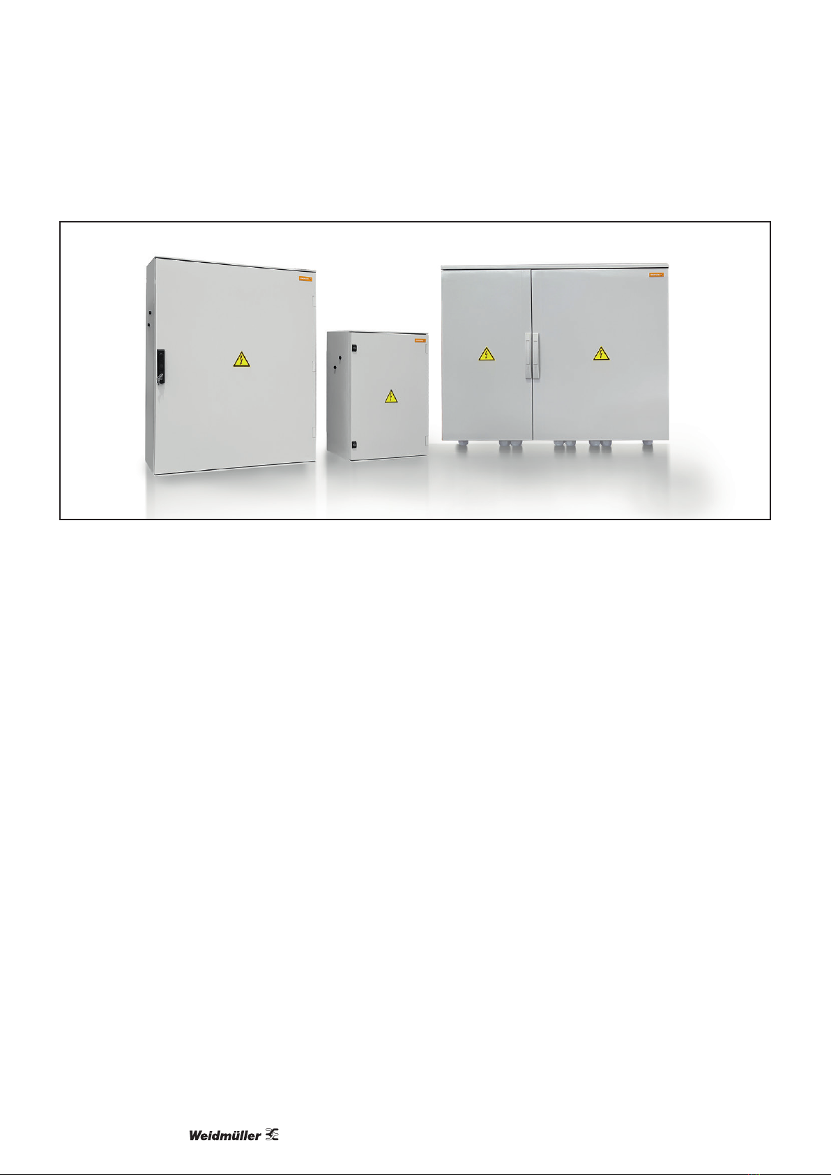
The PV AC combiner box series are intended for use in
photovoltaic (PV) systems designed with string inverters.
The product combines various (2 to 6) string inverter out-
puts into typically one output. The product contains over-
current and overvoltage (optionally) protections at inverter
level. Energy metering devices are provided optionally in
order to monitor the electrical generation of the combiner
box output.
Weidmüller products may only be used for the applications
described in the catalogue and in the relevant technical
documentation.
The observance of the documentation is part of the intend-
ed use.
2.3 Personnel
Work on combiner boxes in the photovoltaic
eld may only be performed by qualied elec-
tricians with the support of trained persons. As
a result of their professional training and expe-
rience, an electrician is qualied to perform the
necessary work and identify any potential risks.
It is a common practise in the sector to apply the ve safety
rules described in the standard EN 50110. Anyway, quali-
ed electricians must analyse case by case on each instal-
lation the best way to proceed with safety.
The ve safety rules are the following:
1. Disconnect completely
2. Secure against re-connection
3. Verify that the installation is dead
4. Carry our earthing and short-circuiting
5. Provide protection against adjacent live parts
2.4 Legal notice
PV AC combiner boxes are CE-compliant in accordance
with Directive 2014/35/EU (Low Voltage Directive) and with
Directive 2014/30/EU (EMC Directive).

4000003077/00/02.20216
3 Device description
Figure 3.1 Product range
3.1 Product overview
PV AC combiner boxes are a complete range of tai-
lor-made solutions for utility-scale photovoltaic systems
designed with string inverters. The combiner boxes are in-
stalled to connect, gather, collect and protect the AC cable
outputs of various string inverters.
The product range oers solutions from 2 to 6 inputs and
1 output, depending on various plant designs. Input of this
product ranges from 400 V to a maximum input voltage of
800 V per string inverter.
The necessary AC inverter outputs are to be connected
at the PV AC combiner box inputs whereas one AC main
cable will be at the output side of the combiner box as a
result of inverters recombination.
Parameters inuencing the selection of the optimal
PV AC combiner box
– Ambient temperature
– Degree of protection needed
– Rated AC voltage of the string inverter
– Rated current of the string inverter
– AC earthing system
– Number of inputs
– Number of outputs
– Over-current protection (fuse links and fuse holders)
– Need of surge protection (Type I + II SPD)
– Energy meter (optional)

74000003077/00/02.2021
Device description
5
1
3
4
2
Figure 3.2 Main components of the PV AC combiner box (example)
1 Circuit breaker or fuses
2 Ground terminal
3 Output terminals
4 Surge protection device
5 End bracket
Figure 3.3 Inputs and outputs of the PV AC combiner box (example)

Device description
4000003077/00/02.20218
3.2 Enclosure
The enclosures of all PV AC combiner boxes are made of
Glass Fibre Reinforced Polyester (GFRP). They provide
IP65 and IK07 or higher in accordance with IEC 62208.
Each enclosure is equipped with hinged door(s). Dierent
enclosure sizes and shape (landscape or portrait) may be
used depending on each project conguration and power
dissipation needs.
Figure 3.4 Enclosure
3.3 Switch disconnector
Figure 3.5 DC switch
PV AC combiner boxes have an AC switch disconnector as
an optional component. The AC voltage of the switch de-
pends on the voltage of the associated PV string inverters.
The switch disconnector (according to the IEC 60947-3)
has been selected to assure that it can switch the circuit at
full load at the maximum operating temperature.
3.4 Surge protection device (SPD)
Figure 3.6 Surge protection device
The surge protection device as an optional component has
been selected corresponding to the customers require-
ments and in accordance with the standard for low-voltage
surge protective devices IEC 61643-32.
3.5 Fuse links
Figure 3.7 Fuse link
The fuses protect the dierent phases of each inverter from
over-current situations. PV AC combiner boxes are provid-
ed with fuse links in accordance with IEC 60269-6:2010.
Each design of PV AC combiner box contains the most
suitable fuse rating specially selected for most common
string inverters in the market, depending on voltage, ambi-
ent temperatures and operation conditions.
ATTENTION
Material damage!
Only use fuses with the selected rating as stated by
Weidmüller technical department.
If you have to replace a fuse inside a PV AC combiner
box, use the same type of fuses delivered with the origi-
nal combiner box. Pay special attention to fuses voltage
and current rate as well as its size and material.

94000003077/00/02.2021
Device description
3.6 Fuse holders
Fuse holders are the interface between the string inverters
output cables and the fuse links. Fuse links provide over-
current protection to the circuit in each and every phase.
The fuse holders ensure that the fuses are placed in the
optimum position to perform their protection function. Ad-
ditionally, the type of fuse holders used in the PV AC com-
biner Boxes from Weidmueller (NH-0X fuse form in vertical
opening under voltage and current) enable authorised per-
sonnel to operate the fuses in a safe manner and open the
circuit under load.
3.7 Conductors
To realise the connections inside the combiner box regard
the following conductor specications:
Inputs Cross section Connection
NH 00 10 mm2... 120 mm2M8
NH 1 25 mm2... 300 mm2M10
NH 3 25 mm2... 300 mm2M12
Outputs Cross section Connection
NH 00 240 mm2... 300 mm2Bolt and nut M12
NH 1 240 mm2... 300 mm2Bolt and nut M12
NH 3 240 mm2... 300 mm2Bolt and nut M12
SPD Cross section
Screw conection 2.5 mm2... 35 mm2
Conductor cross section Tolerance of stripping length
< 4 mm2± 1 mm
6 – 10 mm2± 1.5 mm
> 16 mm2± 2 mm
In order to assure a reliable connection we
recommend to use appropriate crimping tools, as
an example PZ 10 HEX (Order No.1445070000).
Please check the product catalogue to select
the appropriate tool for each cable and wire-end
ferrule.
3.8 Input terminals
Figure 3.8 Cable glands
The PV AC combiner box is equipped with cable glands
that comply with DIN EN 50521 and are TÜV certied. The
cost-ecient cable glands allow the installer to adjust the
necessary number of cables entering and exiting the AC
combiner box to ensure the required water tightness.
3.9 Energy meter (optional)
Figure 3.9 Energy meter D650
In case the PV AC combiner box is equipped with an ener-
gy meter, this device is a D650.
This device simplies the connection work inside the
combiner box and reduces maintenance tasks due to the
PUSH IN terminals. The Transclinic 16i+ can operate at full
load (25 Amps) at maximum temperature range (+70 ºC).

Device description
4000003077/00/02.202110
3.10 General technical data
Main application features
Inputs From 2 to 6 (string inverters)
Inverter size 3 phase string inverters from 60 kW to 250 kW
Output 1
Operating ambient temperature range -10 ºC ... +50 ºC
Ambient conditions during storage -25 °C ... +40 °C, RH 0 % ... 50 %
Installation location Protected outdoors (> 1 km from the sea)
Altitude above sea level Up to 2.000 m (standard), higher altitudes on demand
Main electrical features
Earthing system TN-S, TN-C and TN-C-S
Rated operational AC voltage ≤ 800 V AC (standard), other options on demand
Short-circuit and over-current protections Fuse blocks (3p) with breaking capacity
Rated AC current per input ≤ 135 A
Breaking capacity ≤ 120 kA kA with fuses
Enclosure
Enclosure material GFRP (Glass Fiber Reinforced Polyester)
Enclosure shape Portrait or landscape
Enclosure xing system Wall mounted or pedestal
Degree of protection (acc. to IEC 60529) IP65
Form factor Cabinet with hinged door
Polycarbonate protection plate Optional
Surge protection
Surge protection device Type I + II
Auxiliary contacts No
Surge protection on EIA-RS485 ports No
Optional
Main switch disconnector Optional
Standards
Standards IEC 61439-2 ed 2.0 / EN 61439-2:2011
Please regard data sheet attached to each
combiner box.

114000003077/00/02.2021
4 Transport and storage
4.1 Transporting
► Always wear work shoes with foot protection
when transporting and unpackage the combin-
er box.
►Regard the total weight and use appropriate transporta-
tion equipment.
4.2 Unpacking the delivery
► Before unpacking, check that the product contained is
the one you have ordered (see the label laterally on the
package).
If the product that you have received is not what
you have requested or is incomplete, please do
not open the cartoon boxes. Please contact your
Weidmüller representative oce, your distributor
or the relevant contact person immediately.
► Check the delivery for completeness. For the scope of
delivery, see the enclosed data sheet and dispatch doc-
uments.
If you detect any issue or damage, do not install
the unit. Please contact your Weidmüller repre-
sentative oce, your distributor or the relevant
contact person immediately.
► Store away the transport packaging.
►Ensure that the operating instructions are accessible to
the user at all times.
4.3 Storage
Make sure that in case of long-term storage the following
conditions are met:
– Ambient temperature: -25 °C to +40 °C
– Relative humidity: 0 % to 50 %
ATTENTION
Material damage!
The AC box must be stored lying at on the rear side.
Otherwise the cable glands and connectors at the bottom
of the enclosure can be damaged.
In the event that after the storage there is any ingress of
dirt, pollutants or liquid into the equipment, or the formation
of condensation, damage or any other failures the equip-
ment must not be commissioned until the correct remedial
procedure has been discussed with and approved by
Weidmüller.
4.4 Establishing connections
ATTENTION
Material damage!
The weight of the cables can cause mechanical stress to
the enclosure. For this reason, depending on the installa-
tion height, a strain relief underneath the AC box may be
needed. Regard the national regulations.
– Use only electrical cables rated for the voltages, cur-
rents and environmental conditions (temperature, UV,
etc.) expected at the installation site.
– Ensure that you lay all cables with short-circuit protec-
tion and ground fault protection.
– To ensure short-circuit-proof and ground-fault-proof in-
stallation in accordance with IEC 60364-5-52, the follow-
ing requirements must be fullled:
– Cables must not be installed in the proximity of am-
mable materials or atmospheres.
– Cables must be accessible.
– Cables must be protected against mechanical dam-
age.
– Do not lay the wires over sharp edges.

4000003077/00/02.202112
5 Installation
5.1 Installation site
The PV AC combiner boxes are suitable for protected
outdoor installation. Regard the following aspects when se-
lecting the installation site:
– The location must be protected from the weather and
direct sunlight.
– The location must be easily accessible for installation
work and maintenance work.
– The installation site must not be in close proximity to
easily inammable materials, gases or vapours.
– The combiner box must be positioned as described in
the following section or in other position ensuring the
needed requirements.
– It must be ensured that unauthorised personnel cannot
access the combiner box.
– The installation area must be stable enough to enable
installation and maintenance work safely.
– The combiner box and especially the feeder conductors
must be installed in such a way that damage cannot be
caused by rodents.
– Regard the permissible ambient conditions:
– The temperature range is indicated on the label inside
the box.
– The relative humidity may temporarily be as high as
100 % at a maximum temperature of +25 °C.
– Ensure that no object is blocking the pressure compen-
sation elements.
– When installing, ensure rain cannot penetrate the com-
biner box.
Exposure to direct sunlight and direct rain for
extended periods and excessively high or low
temperatures can result in a shorter lifetime or
damage to the internal components of the com-
biner box.
To protect the combiner box against direct sun-
light and rain, you can install it under the pho-
tovoltaic modules or a protective canopy. Make
sure there is enough air circulation around the
equipment
Figure 5.1 Installation under the PV modules
5.2 Positioning of the combiner box
The PV AC combiner boxes are designed to be installed
vertically with the cable glands or connectors leading down.
Merely a positive inclination from 15º to 90º is allowed.
90°
Figure 5.2 Installation in upright vertical position
The combiner box must not be installed horizon-
tally laying at on the rear neither in any other
orientation.
5.3 Fixation
The xation of the combiner box directly aects
the proper performance and the lifetime of the
product.
Ensure that the requirements described in chap-
ters 5.1 and 5.2 will also be observed.
Mounting material
Most of the Weidmüller combiner boxes are supplied with
metal or plastic mounting lugs, depending on the model.
Fixation screws are not delivered as standard with each
product. Please make sure all needed material is available
before starting the installation.
Requirements
The PV AC combiner box shall be xed to a suitable and
stable metallic structure or a wall that will support the
weight of the combiner box during the entire lifetime.
Always use all xations that are supplied with the combiner
box.
In case the installation is done on a pedestal, the combiner
box should be xed on the top of it with the specic sup-
plied accessories.

134000003077/00/02.2021
Installation
Figure 5.3 Fixing the enclosure to a structure or on a pedestal
5.4 Installing the combiner box
CAUTION
Risk of injury due to the size and the
weight!
►Always install the combiner box with two
persons to avoid any injury or accident.
Installers should be qualied for the specic
works according IEC standards and/or local
regulations and should bring the necessary
safety equipment.
ATTENTION
The product can be destroyed!
– Never drill the enclosure to add any extra hole or to
modify any of the existing holes. Otherwise the IP pro-
tection will get lost as well as the product warranty.
– Lay down the combiner box only on the rear side after
unpacking. Otherwise the cable glands and connectors
at the bottom of the enclosure can be damaged.
► Remove the combiner box from the original packaging.
►Measure the exact distances between the drilling holes
and mark the positions in the mechanical structure (or
wall).
►Drill the holes in the mechanical structure (or wall).
► Mount the combiner box using the xing lugs.
► Check the installation:
– Verify that the combiner box is correctly secured and
xed.
– The surface of the enclosure should be totally at.
Ensure that the combiner box is not bended over the
edges, otherwise the water tightness is not guaran-
teed.
Figure 5.4 Fixing lugs enclosure type A
Figure 5.5 Fixing lugs enclosure type B
Each model has been designed according individual
specications and this has been approved by customer.
Please make sure that during mounting process all
specications and requirements are met according to the
present manual.

Installation
4000003077/00/02.202114
Enclosures mounting lugs and xing points1)
Size
Dimensions H x W x D (mm)
A
B
C D
A
B
mm mm
86
847 x 636 x 300
A 530 A 560
B 665 B 755
C 755
D 890
108
1056 x 853 x 362
A 750 A 750
B 885 B 955
C 955
D 1090
1) This table is a reference. For specic measure of your product please refer to the documentation delivered with the product.
Enclosures mounting lugs and xing points1)
Size
Dimensions H x W x D (mm)
A
B
C D
mm
86
847 x 636 x 300
A 583
B 680
C 782
D 880
108
1056 x 853 x 362
A 783
B 880
C 982
D 1080
1) This table is a reference. For specic measure of your product please refer to the documentation delivered
with the product.

154000003077/00/02.2021
Installation
5.5 Inserting the fuses
Each input associated to one inverter has a set of 3 fuses,
one for each phase. The fuses are carried by a fuse holder
with breaking capacity.
WARNING
Do not operate under load.
A serious damage on persons and equipment
can occur by high voltage.
► When inserting the fuse links please make
sure to wear all safety equipment.
►Ensure that the AC switch disconnector is
in OFF position.
Work through the following steps quickly to avoid
arcing in the fuse contacts.
►First pull the lever of the fuse holder in order to open the
fuse link carrier.
► When the carrier is open, insert the three fuse links and
its blades into the fuse holder carrier clip.
► Once all three fuse links are inserted properly, close the
carrier decisively and quickly until the fuse holder carrier
is fully closed and three fuse-links are fully connected to
the fuse holders.
5.6 Connection of the inputs
The enclosure is equipped with cable glands. No tools are
necessary to x the cables in their position and cover the
gap existing between the cables and the holes drilled in the
enclosure.
In order to realise proper connections we recommend to
use wire end ferrules as well as appropriate stripping and
crimping tools.
Input connections via cable glands
There are various cable entries with their associ-
ated cable gland. Pay attention to the number of
inputs as well as their phases to avoid mistakes
during connection.
Make sure that you have the electrical drawing
provided with the combiner box to hand. Make
sure that the nal input connections match the
electrical drawing provided.
►Insert the AC string input cables (output cables of the
string inverters) through the designated holes at the bot-
tom of the enclosure into the combiner box.
► Make sure the wires pass through their designated cable
gland with their thread in correct position.
►Strip the conductor for the input cross section according
to the ring terminal used with an appropriate tool.
►Crimp the conductor with a tubular wire end ferrule with
15 mm length of the sleeve (the conductive part).
►Pull softly down the cables to ensure that all of them are
properly connected.
► Make sure there is sucient strain relief for the AC input
cables.
► Make sure that the cables are not mounted under stress
conditions.
►Tighten the cable glands.
5.7 Connection of the outputs
The output connections depend on the design of each tai-
lor-made PV AC combiner box. The output cables must be
connected to the poles of the switch disconnector or to the
terminals prepared for this purpose.
Please ensure that the cable that you are going to use ts
with the specications.
– The cross section of the conductor must be selected ac-
cording to the rated current of the system and to the size
of the cable gland of the combiner box.
– Use copper or aluminium cables only. When using alu-
minium cables regard the section "Preparing aluminium
conductors" before starting the installation.
– Weidmüller is not responsible for the performance of the
terminal lugs, terminal ring or terminal cage neither the
output cable selected.
WARNING
Do not operate output cables under
load.
A serious damage on persons and equipment
can occur with components under high volt-
age load.
► If AC output cables from the eld are con-
nected to the terminals ensure the power
supply is disconnected.
►Ensure that the AC switch disconnector is
in OFF position.
►Ensure that there is no voltage in the out-
put cables and that all safety measures
are taken.
►Insert the AC main cables through the designated holes
at the bottom of the enclosure into the combiner box.
► Make sure the wires pass through their designated cable
gland with their thread in correct position.

Installation
4000003077/00/02.202116
►Regard the correct phase of the cables when connecting
the AC conductor to the appropriate terminal lug, ring
terminal or cage terminals and follow the instructions of
that component to crimp it in the right way.
►Connect the AC conductors to the stud terminals or di-
rect to the switch disconnector.
► Check that all connections are performed according to
electrical drawing provided
► Check and apply the right tightening torques to the
terminal lugs of the switch disconnector. The correct
tightening torques can be found in the specic documen-
tation inside each PV AC combiner box.
►Tighten the cable glands.
► Make sure there is sucient strain relief for the AC main
lines/AC feeder cables.
► Close all unused cable glands with blanking plugs to
prevent moisture penetrating the combiner box.
Preparing aluminium conductors
– Aluminium conductors are only suitable for installation
sites that are free from humidity or aggressive atmos-
pheres.
– It is highly recommended to use bimetallic connectors.
– Use neutral gease (e.g. acidfree and alkalifree vaseline)
to protect the surface of the alumimium from oxidation.
As a well known characteristic aluminium forms a thin,
non-conductive layer of oxide as soon as it is exposed to
the air. This layer increases the contact resistance between
the aluminium conductor and the current bar of the terminal
which can lead to poor contact. As a precondition regard
the following steps to prepare the aluminium conductors:
►Scrape the stripped end of the conductor carefully, e.g.
with a knife, to remove the layer of oxide.
Do not use brushes, les or emery paper be-
cause particles of aluminium can be deposited
on other conductors.
►Coat the end of the conductor immediately with a neutral
grease, and connect it to the terminal immediately.
►Tighten the screws of the DC-disconnector with the
maximum permissible tightening torque.
Repeat the above procedure each time after the
conductor has been disconnected and shall be
reconnected.
5.8 Connection of the grounding cable
The PV AC combiner boxes are designed with metallic
mounting plates. The enclosures are made of GFRP (Glass
Fiber Reinforced Polyester). Therefore the unique ground
connector is used for the surge protection. Note that the
earthing cable must be connected to provide the correct
operation of the surge protection device (SPD).
Protective conductors and other earthing conductors for
functional and protective purposes cannot generally be
considered as equipotential bonding dedicated for surge
and lightning protection.
According to the standard CLC-TS 50539-12, the cross
section of connecting conductors to SPDs on the AC side
of PV installations must be as follows:
– Earthing conductors of SPDs Type I+II shall have a min-
imum cross section of 16 mm2copper or equivalent or
equal to the cross section of live connectors, if greater
than 25 mm2.
– The cross section of the connecting conductors from
the SPD to live conductors shall not be smaller than the
cross section of the live conductors of the associated
circuit.

174000003077/00/02.2021
Preconditions for the commissioning
– The installation work has been made according to the
“Installation” chapter of this user manual.
– The ground around the PV AC combiner box is rm and
easily accessible so that work can be done safe.
►Wear appropriate clothes and personal protective equip-
ment.
►Use appropriate tools with the correct insulation.
A multimeter is necessary in order to verify the
absence of voltage in the live parts of the com-
biner box.
► Check that the multimeter is capable to read
the maximum voltage of the string inverter
output and the maximum current owing
through before starting any operation.
DANGER
Imminent risk of life!
High voltages up to 800 V AC are present in
the live parts. Touching live parts can result in
death or serious injury due to electric shock.
► Before starting any work in the PV AC
combiner box:
– disconnect the main switch
– ensure that there are no fuses inserted
into the fuse-holders.
►Ensure that nobody reconnects the unit
while work is not nished or any operator
is still working.
►Ensure that no voltage is present in parts
that are going to be manipulated or that
could be accessible.
►Do not touch live components.
► If specic live parts cannot be insulated or
disconnected, it is mandatory to use addi-
tional safety elements to avoid any risk to
persons or equipment.
6.1 Main indications and inspections
It is recommended to carry out a general inspection on the
PV AC combiner box and the status of the installation be-
fore commencing operation.
The installation must comply with either local and interna-
tional regulations.
Visual inspection
Check the following issues:
– All cables are in good condition.
– There are no hazards around the installation that could
create any damage.
– The cables are connected to the correct phase and ac-
cording to electrical drawing provided.
– The enclosure is rmly xed to the structure, all mount-
ing elements are tightened properly.
– The door of the enclosure is properly closed and the
seal ts all around the door to provide the insulation. As
a check press the door while locking the key-locks a few
times.
– The cable glands are tightened correctly.
– The grounding cable is connected through its own cable
gland and the cable gland is tightened correctly.
– Check the correct status of the SPD. The viewing win-
dow should be in green colour.
Additional inspections issues for combiner boxes
with Energy meter
– The RS485 wire is correctly connected to the specic
terminals inside the combiner box or alternatively to the
D650 connector through its own cable gland.
– The cable gland for communications cable is tightened
correctly.
Measurements
DANGER
Imminent risk of life!
High voltages up to 800 V AC are present in
the live parts. Touching live parts can result in
death or serious injury due to electric shock.
► Before starting any work in the
PV AC combiner box:
– disconnect the main switch
– ensure that there is no current owing
through any of the wires of the box.
6 Commissioning

Commissioning
4000003077/00/02.202118
6.2 Start up
DANGER
Imminent risk of life!
High voltages up to 800 V AC are present in
the live parts.
►Insert fuses into the fuse holders only if
all previous tasks have been nished with
satisfactory results. Never insert fuses un-
der load.
►Use only fuses provided by Weid-
müller within each individual
PV AC combiner box.
►In case the PV AC combiner box has been
provided without fuses, please use the au-
thorised fuses or contact with your Weidmüller
representative for more information.
►Insert the fuses provided with the PV AC combiner box
into the fuse holders using the appropiate tool from
Weidmüller (or equivalent appropriated for this activity).
►Switch on the main switch disconnector (from OFF to
ON position).
► Close and secure the door with the key-tool lock.

194000003077/00/02.2021
7 Accessories and replacing parts
Some parts of the PV AC combiner box can be
replaced in case of damage. Before proceeding
with any of these replacements, we highly
recommend to contact with your Weidmüller
representative to clarify any doubt.
7.1 Replacing fuses
DANGER
Imminent risk of life!
High voltages up to 800 V AC are present in
the live parts.
►Ensure that the AC switch disconnector is
in OFF position.
► Make sure there is no current owing
through any of the wires of the
PV AC combiner box.
►Use only fuses provided by Weidmüller.
► Use only the same type of fuse like the ones inserted in
the other fuse clips of the PCB board (same model and
rate).
►Before replacing fuses, verify that there is no electrical
issue active in the circuit which could cause the blowing
of the new fuse.
►Use the appropriate tool to extract the damaged fuse
and to insert the new one.
► Verify by visual check, that the fuse holder and the fuse
links are free from any damage.
7.2 Replacing surge protection arresters
DANGER
Imminent risk to life!
The contacts in the sockets of the surge pro-
tection arresters are live.
► Do not reach into the sockets when the ar-
rester is removed.
Weidmüller SPDs have three individual arresters. If the
SPD is damaged, the status indicator of the respective ar-
rester will be red.
Figure 7.1 Status indicators of the SPD
►In order to replace an arrester, proceed as shown below.
1.
2.
Figure 7.2 Removing a surge voltage arrester
4.
3.
Figure 7.3 Inserting a surge voltage arrester

4000003077/00/02.202120
ATTENTION
The product can be destroyed!
The enclosure and cover may be damaged by deter-
gents, scouring agents, solvents and high-pressure
cleaners.
►Use a cloth moistened with clear water for cleaning.
►Clean the enclosure at regular intervals so that the
warning symbols are always clearly visible.
►Only clean the exterior of the enclosure when it is
closed.
► Take care not to damage the sticker with warning sym-
bols.
8 Cleaning
Table of contents
Other Weidmüller Power Distribution Unit manuals
Popular Power Distribution Unit manuals by other brands

Essential Audio Tools
Essential Audio Tools Mains Multiplier 6+ user manual

Pepperl+Fuchs
Pepperl+Fuchs GUB Series Brief instructions

ABB
ABB PEC 827E product manual

Wiremold
Wiremold Power Commander installation instructions

ATTEMA
ATTEMA FTTX instruction manual

LifeSafety Power
LifeSafety Power FlexPower A8 installation manual