Weidmüller VPU IOT AC II 3 Plus 1 300/50 User manual

VPU IoT AC II
VPU IOT AC II 3+1 300/50 2735900000
Surge Protection Device
Operating instructions

2807610000/00/09.20212
Content
1 About this documentation 3
1.1 Target group 3
1.2 Symbols and notes 3
2 Safety 4
2.1 Intended use 4
2.2 Personnel 4
3 Transport and unpacking 5
3.1 Unpacking the product 5
4 Device description 6
4.1 Operating modes 6
4.2 Technical data 7
5 Mounting and electrical installation 8
5.1 Mounting 8
5.2 Electrical installation 8
6 Setup 9
6.1 Startup 9
6.2 Initial commissioning 9
6.3 Conguration 9
6.4 Performingarmwareupdate 11
6.5 Networkandsecuritycongurationsettings 12
6.6 MODBUS registers map 13
7 Operating the device 14
7.1 Dashboard 14
7.2 Getting information about the device 15
8 Troubleshooting and spare parts 16
8.1 Troubleshooting 16
8.2 Spare parts 16
9 Disposal 17
Manufacturer
Weidmüller Interface GmbH & Co. KG
Klingenbergstraße 26
32758 Detmold, Germany
T +49 (0)5231 14-0
F +49 (0)5231 14-292083
www.weidmueller.com
Document No. 2807610000
Revision 00/September 2021

32807610000/00/09.2021
1.1 Target group
These operating instructions are intended for the operator
of the product and for all persons handling the product dur-
ing its life cycle.
1.2 Symbols and notes
The warnings contained in the documentation are divided
into hazard categories.
DANGER!
Notes with the signal word "DANGER" warn you of situa-
tions which will result in serious injury or death if you do not
observe the specied instructions.
WARNING!
Notes with the signal word "WARNING" warn you of situ-
ations which may result in serious injury or death if you do
not observe the specied instructions.
CAUTION!
Notes with the signal word "CAUTION" warn you of situ-
ations which may result in injury if you do not observe the
specied instructions.
NOTICE!
Notes with the signal word "NOTICE“ warn you of a danger
which may result in material damage or malfunctions of the
product if it is not avoided.
The situation-dependent warnings may contain the follow-
ing warning symbols:
Symbol Meaning
Warning of dangerous electrical voltage
Warning of electrostatically charged compo-
nents
Qualied electrician necessary
Notes on the documentation
Additional formatting is used in the rest of the text which
has the following meaning:
Sections of text next to this arrow contain infor-
mation which is not related to safety, but which
provides important information regarding correct
and eective work.
► All instructions can be identied by the black triangle
next to the text.
– Lists are indicated with dashes.
►Store the instructions such that they are
available at all times. Do not store the in-
structions in the product enclosure.
The document is available to download from
the Weidmüller website.
►Also refer to the inverter manufacturer's
documentation.
1 About this documentation

2807610000/00/09.20214
2 Safety
DANGER!
Risk of electric shock!
Live parts carry high voltage during operation.
►The device has to be covered under the installation
hood before pressing the operation button for commis-
sioning.
►Only switch on and use the device when all conductors
are connected and all arresters are mounted in the sock-
et.
►Do not use the device near explosive gases, vapours or
in a humid environment.
►Do not use damaged product.
► Do not insert any foreign objects into the contact sockets
of the device.
NOTICE!
Risk of material damage!
►Only use the device for its intended purpose.
►The device must not be used if it is damaged or other
defects have been identied.
► The device must not be opened, modied or converted.
► Use only the specied spare parts and accessories.
►Use only the supplied test leads.
►Use the test leads only together with the supplied test
adapter.
2.1 Intended use
The VPU IoT AC II is a type II surge protection device
(SPD). The device is used for protecting low-voltage con-
sumer installations and electrical or electronic devices from
the surge voltages which occur from atmospheric discharg-
es (lightning) or from switching operations (transients).
The device detects overcurrent events as well as earthing
faults in the plant. The device can be connected to a cloud
via IoT.
The device must be mounted in an IP20 cabinet that is ac-
cessible by authorised personnel only.
2.2 Personnel
Only qualied electricians may carry out the installation,
the initial commissioning, the reset and troubleshooting.
Conguration can also be done by trained users

52807610000/00/09.2021
►Transport the device to its destination in its original
packaging.
►Observe the instructions regarding handling, moisture,
shock, tilt and temperature indicators on the packaging.
► Observe the humidity specications and the temperature
range specied for transport.
►Protect the surfaces as necessary to prevent damage.
►When transporting the equipment or storing it temporar-
ily, make sure that the surfaces are protected from the
elements and any external inuences, and that they are
kept dry and clean.
3.1 Unpacking the product
► Unpack the product and the instruction sheet.
►Never install a damaged or otherwise defective surge
protection device.
3 Transport and unpacking

2807610000/00/09.20216
The VPU IoT AC II is a surge protection device (SPD) that
detects overcurrent events as well as earthing faults in the
plant. The device can be connected to a cloud enabling
digital services. The current device status can be trans-
ferred and monitored via internet.
The measured data and detected events are transmitted
and permanently stored in the cloud. The current device
status is visualised and enables predictive maintenance
activities like replacement in time. The device status can
be:
– SPD fully functional
– SPD still functional
– SPD replacement recommended
– SPD defective, replacement necessary
The detection of transient overvoltages is very sensitive,
so that even the smallest events can be detected. Conclu-
sions about the power quality in a TN-S or TT system can
be drawn from the number and frequency of events.
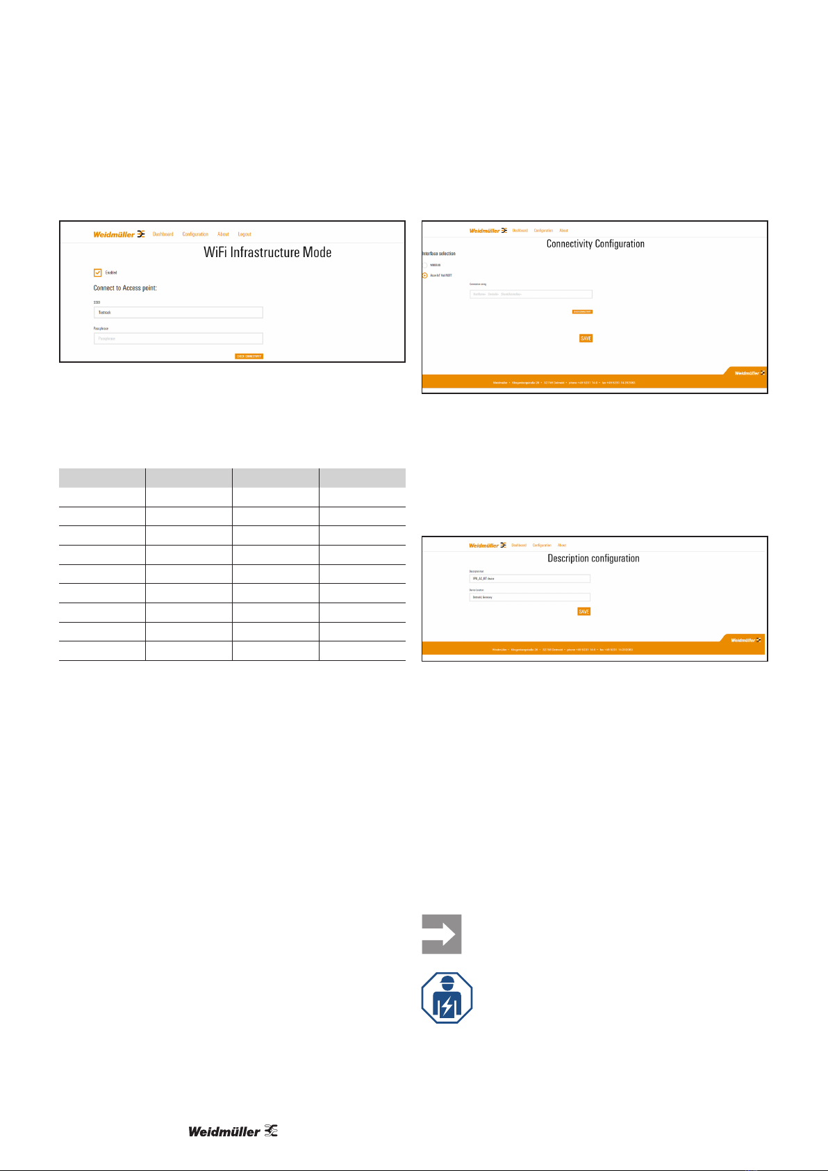
For the internet connection a Wi-Fi network is required with
reliable connection quality during the whole life cycle of the
device. The Wi-Fi network must provide internet access for
the device to deploy a public cloud endpoint.
3
4
2
1
5
6
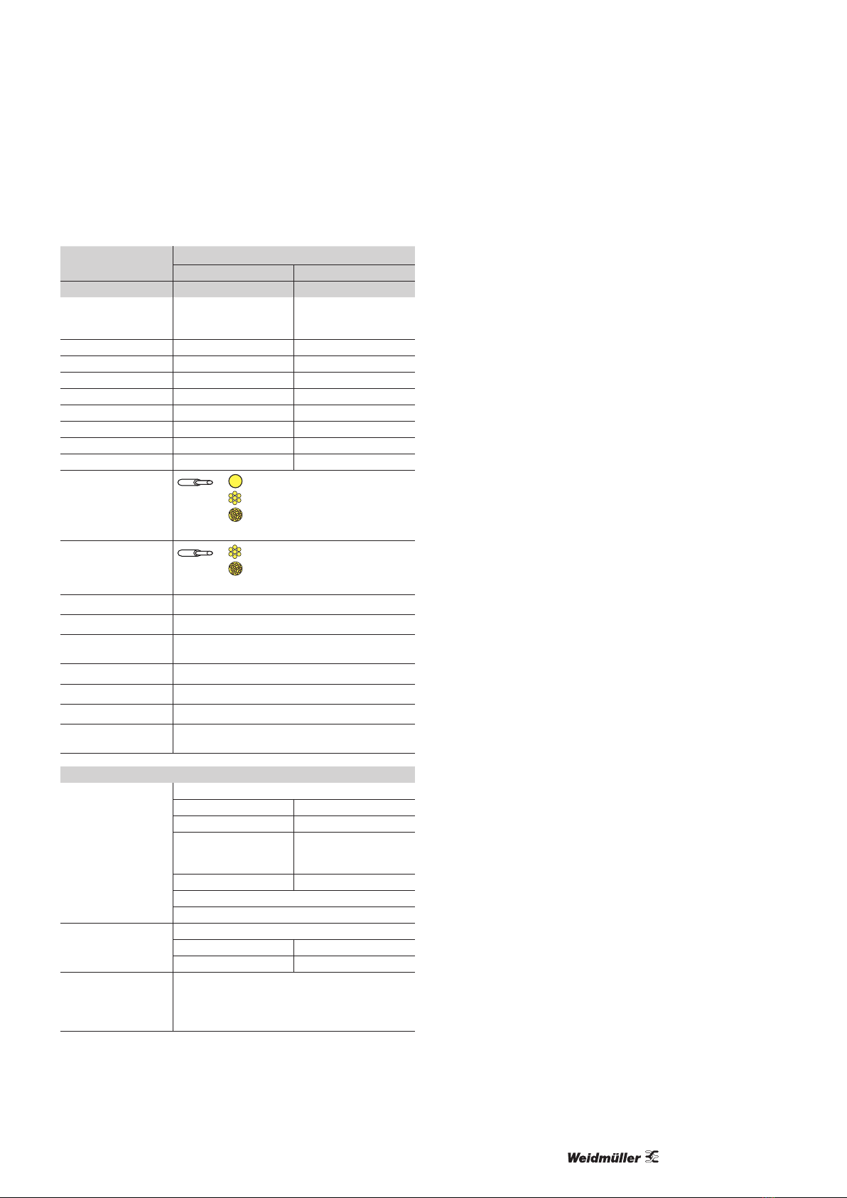
Figure 4.1 Device description
1 Clamping points for L1, L2, L3 and neutral
2 Statuswindow
3 Arrester
4 PE clamping points
5 Operation button
6 LED
4.1 Operating modes
Factory default mode
------------------------------------
Wi-Fi hotspot ON
Auto-expiry in 30 min
------------------------------------
LED is permanently green
Maintenance mode
----------------------------------------
Wi-Fi infrastructure connected
Wi-Fi hotspot ON
Auto-expiry in 10 min
----------------------------------------
LED flashes green fast
Normal operation mode
----------------------------------------
Wi-Fi infrastructure connected
Wi-Fi hotspot OFF
----------------------------------------
LED flashes green slowly
Figure 4.2 Operating modes
LED indicators
LED status
Priority Type Duration Factory default Normal
operation
Temporary
hotspot
0 Search Instant Green,fastflashing
1 SPD fault Long Red, permanent
2 Leakage Long Red, permanent
3 Earth fault1Long x Red, permanent
4TOV Long x Green,fastflashing
5Phase
loss2Long Red, permanent
6 Wi-Fi loss Long x Red,fastflashing
1 Manually triggered
2 See Chapter 7.1
Factory default
– LED ashes green fast for 3 seconds. If the Wi-Fi hot-
spot is on, the LED lights permanently green
– change of the default values via user interface
Normal operation
– LED ashes green slowly
Temporary hotspot (Maintenance)
– LED ashes green fast
– for the initial device setup
–for the change of essential con guration
– the current IP can be read out via user interface with
DHCP
4 Device description

72807610000/00/09.2021
Device description
4.2 Technical data
VPU IoT AC II
N-PE L-N
Type 305 V 300 V
Grid (Un) @ 50...60 Hz
230 V
N-PE
spark gap
230/400 V
TN, TT
Voltage regulation ±10 % ±10 %
Un0 V 240 V
In/ Imax (8/20 µs) 40/65 kA 20/50 kA
IPE 1 µA 0.33 mA
II–100 Arms
ISCCR – 25/50 kA
Up@ In≤1500V ≤1500V
Uc305 V 300 V
Wire cross-section min.
2.5 mm2 (AWG14)
2.5 mm2 (AWG14)
2.5 mm2 (AWG14)
l = 18 mm / 2...3 Nm
Wire cross-section max.
2.5 mm2 (AWG2)
2.5 mm2 (AWG2)
l = 18 mm / 2...3 Nm
Ambient temperature -40...+85 °C
Storage temperature -40...+85 °C
Relative humidity
(non-condensation) 5...95 %
Altitude 4000 m
Degree of protection IP20, built-in
Height x Width x Depth 90 x 108 x 68 mm (one port SPD)
Approvals / applied
standards / directives CE, IEC/EN 61643-11
Communication settings
Maintenance interface
IEEE 802.11 b/g/n Access Point
Frequency band 2.4 GHz
Encryption WPA/WPA2
SSID
VPU_AC_IOT_
xxxxxxxxxxxx (full
MAC address)
Password Detmold01
Temporary access (default 10 min)
Limited to a single STA
Wi-Fi interface
IEEE 802.11 b/g/n STA
Frequency band 2.4 GHz
Encryption WPA/WPA2
Operating systems
supported
Windows10
Android 8 or later
iOS 13 or later

2807610000/00/09.20218
5 Mounting and electrical installation
5.1 Mounting
See instruction sheet in the packaging box.
5.2 Electrical installation
The installation must be carried out by a
qualied electrician in accordance with the
information in the instruction sheet and the
local conditions and standards.
If the product is damaged, do not install and
use the product.
►Carry out the wiring according to the intended applica-
tion (see instruction sheet).
If the product has already been installed elsewhere and is
now being reused, follow the instructions to restore the de-
vice to its factory defaults, see Chapter 6.3.
The LED indicator on the device lights permanently green if
installed correctly.

92807610000/00/09.2021
6.1 Startup
Prerequisites:
– The power supply must be switched on. The LED lights
permanently green.
– For the setup you need a Wi-Fi capable device and a
supported browser, see Chapter 4.2.
The startup procedure includes the following steps:
– initial commissioning
– conguration
6.2 Initial commissioning
The commissioning must be carried out by a
qualied electrician.
►Create a temporary hotspot by pressing the operation
button 5 times briey.
The LED ashes green for 3 seconds.
The temporary hotspot mode is now activated for a period
of 10 minutes. After this time the hotspot mode is automati-
cally switched o.
►Connect to the hotspot of the device via a Wi-Fi capable
device, e.g. tablet.
Figure 6.1 Using a Wi-Fi hotspot
The unit's SSID is displayed as VPU_AC_IOT_
xxxxxxxxxxxx (x = full MAC address). The default pass-
word is Detmold01.
If the SSID of the unit is not visible, the tempo-
rary hotspot mode has expired.
►Reactivate the temporary hotspot mode as
described above.
► Check the voltage level, the leakage current and the sta-
tus of the arresters.
6.3 Conguration
The conguration is done via user interface. A change of
Wi-Fi and connection settings is only possible in temporary
hotspot mode. By clicking Configuration the following set-
tings can be edited:
– Wi-Fi
– Modbus connection
– cloud connection (Cloud)
– device description (Description)
– user password (Change Password)
– factory reset
Changes have to be conrmed by clicking the SAVE but-
ton.
Conguring the Wi-Fi
Prerequisite:
You must be able to access the device via IP address in his
wireless network.
►Open the browser and enter the IP address 172.22.87.77.
► Click Configuration.
► Click Connectivity, WiFi.
►Enter the user name and the password.
The default user name is admin and the default password is
SmartSPD.
The password must be changed upon rst login.
Figure 6.2 Changing the password
►Connect to the access point of the user's wireless net-
work.
► Click Enabled.
► Click CHECK CONNECTIVITY.
A Wi-Fi test is performed.
6 Setup

Setup
2807610000/00/09.202110
Figure 6.3 Connecting to the Wi-Fi
After the Wi-Fi test you can proceed with further congura-
tion. It is also possible to set a static IP address.
Services list applicable to Wi-Fi interface
Service Protocol Port Traffic
DHCP UDP 67 Outbound
DHCP UDP 68 Inbound
DNS UDP 53 Outbound
DNS TCP 53 Outbound
HTTP TCP 80 Inbound
HTTPS TCP 443 Outbound
MODBUS TCP TCP 502 Inbound
NTP UDP 123 Outbound
PING ICMP N/A Inbound
Conguring the connection via Modbus
►Load the website of the device.
►Select the Modbus interface.
Conguring the cloud
►Create a cloud account (WM Cloud or third party cloud).
►Add the device.
The cloud generates communication parameters.
Connecting to the cloud
Prerequisite:
– You have created a cloud account.
►Load the website of the device.
► Click Connectivity, Cloud.
►Select the Azure IoT interface.
Figure 6.4 Connecting to the cloud
►Enter the connection string.
The device will conrm the communication with the cloud.
Conguring the device description
► Click Description.
Figure 6.5 Description configuration
►Enter a text as a device description.
►Enter the device location.
Changing the password
► Click Change Password.
►Enter the current password.
►Enter the new password and retype it.
Resetting to factory defaults
In case of changing the application it may be necessary to
reset a device.
For security reasons it is recommended to reset
a device before it is replaced.
The reset to factory defaults must be carried
out by a qualied electrician.
►Load the website of the device.
►Open Reset configuration to factory defaults.

112807610000/00/09.2021
Setup
►Enter the user name and the password.
Figure 6.6 Resetting to factory defaults
► Click the RESET button.
6.4 Performing a rmware update
► Check the Weidmüller website for recent updates.
► Download the current rmware, including the README
le.
► Perform the actions described in the README le.

Setup
2807610000/00/09.202112
6.5 Network and security conguration
settings
The following settings are recommendations according to
IEC 62443-4-2.
Item Section Configuration
settings
Recommendation Event Comment
1 Operator account Operator pass-
word
Strongpassword No event Useastrongpasswordwithletters,digitsandsymbols.The
passwordshouldconsistofatleast8characters.
2
Wi-Fi STA /
Infrastructure
SSID With a button the connection can be validated.
3Password With a button the connection can be validated.
4 Enable DHCP Enabled Not enabled MostWi-FinetworksuseDHCPforIPassignmentandother
networkcongurationparameters.Itisrecommendedtouse
DHCP if available.
5 IP address Unique IP address
inside the Wi-Fi
networksubnet
Invalid IP address such as for
broadcast, reservered for lo-
calhost, subnet address, public
address(derivefromgateway)
orequaltothegatewayIP
address
PleaseuseauniqueIPaddressinsidetheWi-Fisubnetwork.
Note: Should be disabled in case DHCP is used.
6 Netmask
Default value:
255.255.255.0
Valid netmask Maskpatternbeginsnotwith8-
30"1"sandisfollowedby"0"s.
Thenetmaskisnotrecommended.MostprivateIPnetworksuse
netmasks, e.g. 255.255.255.0.
Note: Should be disabled in case DHCP is used.
7Gateway Valid IP address PleaseuseaGatewayIPaddressinsidetheWi-Fisubnetwork.
TypicallythegatewayhastherstvalidIPaddressofthe
subnetwork,e.g.withanetmaskof255.255.255.0itcouldbe
192.168.1.1.
Note: Should be disabled in case DHCP is used.
8 Enable automatic
DNS server
It is recommended to obtain the DNS server IP addresses auto-
matically via DHCP
Note: Should be deactivated in case DHCP is not used.
9 DNS server 1 On-premise IP
address of different
subnetwork
IPaddressinsubnetworkor
always
TypicallytheDNSIPaddressisaIPaddresswhichisnotinthe
samesubnetworkbutstillon-premise.
Note: Should be disabled in case automatic DNS is used (Pos. 8)
10 DNS Server 2 On-premise IP
address of different
subnetwork
IPaddressinsubnetworkor
always
TypicallytheDNSIPaddressisaIPaddresswhichisnotinthe
samesubnetworkbutstillon-premise.
Note: Should be disabled in case automatic DNS is used (Pos. 8).
11 NTP server (IP/
domain)
On-premise IP
address of different
subnetwork
IPaddressinsubnetworkor
always
TypicallytheNTPIPaddressisaIPaddresswhichisnotinthe
samesubnetworkbutstillon-premise.
12
Cloud connection
is enabled
13 Connection string No Pleasedonotstoretheconnectionstringpermanentlysomewhere
else in order to reduce the chance of misuse.
13 Modbus TCP is enabled See MODBUS registers map

132807610000/00/09.2021
Setup
6.6 MODBUS registers map
Address Item
0xA000 Last PE measurement timestamp (high part, uint16)
0xA001 LastPEmeasurementtimestamp(lowpart,uint16)
0xA002 Last PE measurement result (0 or 1; 0=error)
0xA010 Last Surge event timestamp (high part, uint16)
0xA011 LastSurgeeventtimestamp(lowpart,uint16)
0xA012 Surge events counter (uint16)
0xA013 Last Surge severity (0 or 1; 0=surge during PE error, 1=surge
during proper PE)
0xA020 Last SPD status change event timestamp (high part, uint16)
0xA021 LastSPDstatuschangeeventtimestamp(lowpart,uint16)
0xA022 Latest SPD status (0 or 1; 0=error)
0xA030 Last Leakage measurement timestamp (high part, uint16)
0xA031 LastLeakagemeasurementtimestamp(lowpart,uint16)
0xA032 Latest Leakage value (uint16; unit is 0.1mA -> value 45 repre-
sents 4.5 mA)
0xA033 Latest Leakage status (0 or 1; 0=error)
0xA040 Last Voltages measurement timestamp (high part, uint16)
0xA041 LastVoltagesmeasurementtimestamp(lowpart,uint16)
0xA042 Latest Phase 1 Voltage (uint16; unit is 0.1 V -> value 2405
represents 240.5 V)
0xA043 Latest Phase 2 Voltage (uint16; unit is 0.1 V -> value 2413
represents 241.3 V)
0xA044 Latest Phase 3 Voltage (uint16; unit is 0.1 V -> value 2405
represents 240.5 V)
0xA050 Last Phase 1 TOV event timestamp (high part, uint16)
0xA051 LastPhase1TOVeventtimestamp(lowpart,uint16)
0xA052 Phase 1 TOV events counter (uint16)
0xA053 Current Phase 1 TOV status (0 or 1; 0=ongoing TOV)
0xA054 Last Phase 2 TOV event timestamp (high part, uint16)
0xA055 LastPhase2TOVeventtimestamp(lowpart,uint16)
0xA056 Phase 2 TOV events counter (uint16)
0xA057 Current Phase 2 TOV status (0 or 1; 0=ongoing TOV)
0xA058 Last Phase 3 TOV event timestamp (high part, uint16)
0xA059 LastPhase3TOVeventtimestamp(lowpart,uint16)
0xA05A Phase 3 TOV events counter (uint16)
0xA05B Current Phase 3 TOV status (0 or 1; 0=ongoing TOV)

2807610000/00/09.202114
7 Operating the device
During normal operation, the device is sending periodic or
triggered process data as well as connection information
(RSSI, latency).
7.1 Dashboard
The dashboard is displayed every time the device is ac-
cessed via IP address. In the dashboard you can nd a
summary of the following monitored values:
– SPD Status
–Leakage
– Last Surge timestamp
– Grounding
– Phase 1 Voltage level or Phase loss
– Phase 1 Last TOV timestamp
– Phase 2 Voltage level or Phase loss
– Phase 2 Last TOV timestamp
– Phase 3 Voltage level or Phase loss
– Phase 3 Last TOV timestamp
Phase loss: Limit value of 190 V is reached
Phase loss alarm: 190 V for > 5 s
Figure 7.1 Measurements summary
► Click Dashboard and select the menu item you want to
open:
Events log
In the Events log view,a table with the latest events, in-
cluding a description and a timestamp, is displayed.
Figure 7.2 Latest log records
SPD status
In the SPD Status view,the operating status is displayed:
Pass or Fail.
Figure 7.3 SPD status
Leakage current monitoring
The leakage current is an indicator of the ageing of the ar-
resters. Lightning or overvoltages from the application will
accelerate the ageing process.
In the Leakage view, the leakage current status is dis-
played:
Pass or Warning.
Figure 7.4 Leakage current monitoring

152807610000/00/09.2021
Operating the device
Surge history
In the Surge view, the number of surges with timestamp is
displayed.
Figure 7.5 Surge history and monitoring
Grounding state
An SPD requires a proper earthing connection.
In case of an overvoltage, the device is discharged via the
earth conductor.
In the Grounding state view, the earthing status is dis-
played.
Figure 7.6 Grounding state monitoring
Earth loop impedance alarm
TT System limit value: 10 Ohm
TN-S System limit value: 1 Ohm
Earth loop impedance monitoring should be enabled only
if the device is installed before a residual current device
(RCD), since the function causes the RCD to trip.
►If you want to enable earth loop impedance monitoring,
enter the following command in the address bar of your
browser: https://172.22.87.77/eli_trigger.html
All messages are time-stamped and stored in the cloud.
TOV monitoring
Arresters must be able to withstand persistent voltage
increases with mains frequency. These temporary overvolt-
ages (TOVs) can occur by various error states inside and
outside the low voltage consumer facility of a building.
In the TOV events view, the TOVs are displayed.
Temporary overvoltage alarm: 264 V for > 5 s
Figure 7.7 TOV monitoring
7.2 Getting information about the device
► On the starting page, click About.
Figure 7.8 About the device

2807610000/00/09.202116
8.1 Troubleshooting
Fault Possible cause Remedy See chapter
An error message is sent via user
interface.
Device is shown as oine
No cloud connection ►Reconnect. The synchronisation of
missed last data begins.
6.3
LED ashes red, signalisation
also via captive portal
No Wi-Fi connection ►Reconnect. The synchronisation of
missed last data begins.
► Switch o and on the device.
6.3
LED lights permanently red The device is not properly
installed.
► Check the installation. 5.2
The arresters are not in or-
der.
► Check the correct t of the arrest-
ers and the locking mechanism.
5.2
Device is out of order The device has no power
supply or the device is bro-
ken.
► Check the power supply.
►Reset and replace the device.
A leakage current warning is sent
via user interface or the status
window of the arrester is red.
The arrester is at the end of
the operating lifetime.
►Replace the arrester, see instruc-
tion sheet.
8.2 Spare parts
Product Order No.
Arrester 2810460000
ScrewdriverSDIKSLIMPH1X80 2749650000
8 Troubleshooting and spare parts

172807610000/00/09.2021
Products marked with this symbol are subject
to Directive 2012/19/EU: Collection and re-
cycling of electrical and electronic equipment
(WEEE). These products contain substances
that may be harmful to the environment and
human health. They also contain substances
that can be reused through targeted recycling.
►Observe the notes for proper disposal of the
product. You can nd the notes here:
www.weidmueller.com/disposal.
9 Disposal
This manual suits for next models
1
Table of contents
Other Weidmüller Surge Protector manuals
Popular Surge Protector manuals by other brands

Novus
Novus NVS-1601CB user manual

Technicolor - Thomson
Technicolor - Thomson SpikeMaster user guide

Raycap
Raycap RSCAC-1333-P-240-A Install instructions

Eaton
Eaton MEMSHIELD 3 EPBN1SPD123 Installation instructions manual

Monster Power
Monster Power Monster Power PRO 3600 owner's manual

Spectracom
Spectracom 8226 Installation guides

Rocket Fish
Rocket Fish RF-HTS105 Guía De Instalación Rápida

Rocket Fish
Rocket Fish RF-HTS100 Guide d'installation rapide

Tripp Lite
Tripp Lite IBV-12 owner's manual

Tripp Lite
Tripp Lite SPIKESTIK Specifications

Tripp Lite
Tripp Lite TLP604TEL Specifications

Rocket Fish
Rocket Fish RF-HTS1215 Quick setup guide