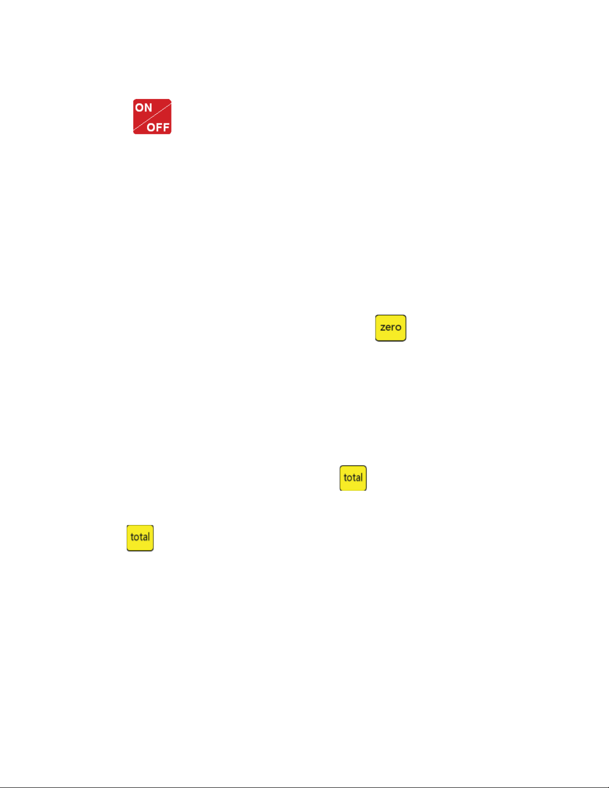
WEIGHSOUTH WS 10 User manual

WS 10
Weighing indicator
USER MANUAL
Edition:10052001A

Safety Instruction
For safety operation follow the safety instructions.
WARNING
WARNING
WARNING
Setting, Calibration Inspection and Maintain of the indicator is
prohibited by Non-professional sta.
Please make sure the weighing display have good ground in using
e indicator is the static and sensitive equipment,
cut o the power during electrical connections,
internal components touched by hand is prohibited,
and please take the measure of anti-static.

1. Technical Parameters
is weighing indicator is designed for bench scale. Floor scale,
the basic weighing function include: Hold. Print kg/lb conversion .
optional: I/O , 4-20mA output.
1.1 Main function
Weighing function:
Zero, tare, G.W, N.W, accumulation. printing, animal -weighing.
kg/lb convert. Overload remind.
Print format: S.N. G.W N.W Tare. Date, Time
1.2 Technical parameter
AC power AC100~250V
Operation temperatur - 10 °C ~ + 40 °C
Operation humidity ≤90%RH
Storage temperature - 40 °C ~ + 70 °C
Accuracy class 6000 e
Resolution display: 30, 000 ADC: 2,000,000
Zero stability error TK0 < 0.1μV//K
Span stability error TKspn < ± 6 ppm//K
Sensitivity (internal) 0. 3 μV /d
Input voltage -30~30mV DC
Excitation circuit 5 VDC, 4 wire connection,
Maximum connect 6 load cell of 350Ω
Options:
Pinter
RS232/RS485 serial interface or second display
I/O
4-20mA

Ensure that all parts are accounted for:
• WeighSouth WS10 Indicator
• Weighing Platform
• Column
• Wall Mount Bracket
• Required parts bag
• Operation manual
e correct location is crucial to the accuracy of the weighing
results. Select a stable, vibration-free and level location. e ground
must be able to safely bear the weight of the fully loaded scale.
1. Set the weighing platform on the selected level workplace
2. Aer rst removing the platter, loosen the shipping screws
located at each corner of the platform. ree full turns of
the screws is necessary. e scale will not function properly if
the shipping screws are touching the top sub assembly.
3. Attach the column to the underside of the bottom frame by
using the 4 hexagon head screws supplied. On certain models
choose which side of the weighing platform will better suit
your needs.
4. Tuck the load cell cable in the column and out the top of the
column.
5. Attach the indicator to the column using the umb screw
provided.
6. Attach the Load cell connector to the WS10 Indicator by lining
up the ports correctly.

1.3 Drawing

1. When you use the internal battery rst time, you should
charge the battery fully, to prevent low voltage resulted from
self leakage of battery.
2. When the “battery” light is on, means low battery.
3. e light turns to yellow during charging
4. When the light turns to green, means fully charged.
5. If the battery is not used for a long time, take it out to avoid
leakage
1.4 Battery instruction

2. Basic Operation
2.1 Keys
LED Instruction
Weighing data
kg kg
lb lb
Hold Data hold
Gross Gross weight
Net Net weight
Tare tare

Keys Key Name Key function
Print
1. Work with “ZERO” TARE” “ON/OFF” key
to perform many functions.
2. Print
Zero Zero the weight within tolerance
Tare At G.W mode, get the tare weight. At
N.W mode, clear the tare, get the G.W
GrossWeight At N.W mode, check the G.W, aer 3
seconds back to N.W automatically
Counting Counting operation
Kg/lb Convert Convert between kg and lb
Accumulation
1. Accumulation
2. work together with “ Print” to perform
e accumulation function and check the
accumulation result
Power On/O Press 2 seconds to power on or power o
Keys function
e weighing data is stable
Weight is zero
Hi Overload
OK Ok
Lo Underload
.Decimal
PCS Show the counting status
TOTAL Go to accumulation mode

2.2
Power on & o
Press 2 seconds to power on or power o, aer power on the
indicator show ”000000-999999”.
2.3 Zero operation
1. Initial zero setting:
When power on the indicator, if the weight on the scale
is within the initial zero tolerance, indicator show zero
automatically.
2. Manually Zero setting:
When the scales is stable, and not the negative display, you can
zero the weight within tolerance by press key.
2.4 Tare operation
Press “TARE” key, the gross weight is tared, indicator shows
the Net weight, the “Net” “tared” status light is on. At tare mode,
Press” TARE” key, clear the tare weight, the indicator will show the
gross weight.
2.5 Accumulation operation
At Zero mode, load weight till stable, Press go to accumulation mode,
”Total” light on, display” n 001”, and then display loaded weight; unload
the weight, back to zero, load the second weight again till stable.
Press display”n002” then display the second loaded weight. Repeat
Check the accumulation
Press “PRINT “key and hold it then press “TOTAL”” key,
display ”n**”, (it is the accumulating times) then show total weight.
there are 8 digits totally. It shows the rst 4 digits then the last
4 digits. For example, the rst 4 digits is”0012”, the last 4 digits
is”34,56” It means the actual weight is “1234.56”
it agin and again, maximum 999 times.

EXIT the accumulation function
When the indicator show the last 4 digits, Press hold it, the
indicator shows “clrn”, it means don’t clear the total Weight, Press
“PRINT” key to exit it; if you want to clear total weight, Press
“ZERO” or “TARE” key, “clrn” change to “clry” it means clear total
weight, then Press “PRINT” to clear the total weight and exit ac-
cumulating mode.
2.6 Print
2.7 Hold
2.8 COUNT
If the weighing is stable, aer connected with printer press
”PRINT” can print the weight. Note: at tare mode, print with tare.
If negative weight, cannot print. Set C30 for time format.
ere are two dierent hold functions. Peak hold function
and data hold function the setting is dierent accordingly.
C11=3 Automatic hold function
C11=0 close hold function.
1. At weighing mode, load the weights on the platform scales,
Press ”Count” the indicator show” PCS 0” press” Zero” key
input the quantity and press” Print” to conrm it.
2. Load the goods on the platform scales and then the indicator
will show the quantity.
3. Press” Count” back to weighing mode.
4. If you want to weigh dierent goods, at weighing mode, put
the sample on the platform scales, press” Count” the indicator
show ”0” Press “ Count” hold it and then press “ ON/OFF”
the indicator show” PCS 0”, press “Zero” input the sample
quantity, press “ Print” to conrm it. en repeat the step 2
and 3.

3. Calibration and Parameter setting
3.1 Enter setting
ere have two methods to enter the setting menu:
1. When the switch “ CAL” is o, press the “PRINT” hold it and
then press” HOLD” enter C08-39 setting.
2. Take out the sealing screw on the back of indicator, then press
“CAL”, at the “SPAN” position as below. press “PRINT” hold it
and then press “HOLD” key , enter C01-C39 setting.
e key functions in setting:
Enter
Up
Down
Power switch. Exit setting
Exit & Save

3.2 Step of calibration operation:
According to the second method which can enter setting menu,
C01-C39
Step Method of
Operation
Display Remark
1[C01 ] Aer you enter calibration mode, it
displays [C01 ]
2
press [C01 1] Weight unit
option: 1= kg
2= lb
3press
press
press or
[C02 ]
[C02 0]
[C02 2]
Set decimal digits
option: 0/1/2/3/4
Select decimal digit example:
two decimal point: [C02 2]
4press
press
press or
[C03 ]
[C03 1]
[C03 5]
Set graduation option:
1/2/5/10/20/50
Select required graduation example:
graduation 5: [C03 5]
5press
press
press or /
[C04 ]
[0100.00]
[0100.00]
Max capacity
Example: max weighing 100kg:
[0100.00]
6press
press
press
press
[C05 ]
[C05 0]
[C05 1]
[CAL 9]
°°°°°°°°
[0000.00]
Zero calibration Option
0= No need zero calibration
1= Need zero calibration
Calibration zero please choose
1 and ensure scale is empty and
“stable” light is on. Ensure zero
calibration, countdown till
show[0.00] (example for two
Decimal point)
7press
press
press or
press
[C06 ]
[C06 0]
[C06 1]
[SPAN ]
Calibration option:
0= No need calibration
1= Need calibration
Load weights on scales according to
max. capacity. Suggest close to the
max capacity, at least 10% of max.
capacity

press or
press
[0100.00]
[0080.00]
[CAL 9]
……
[0080.00]
[CAL
End]
For example: the weights is 80kg
As bellows:
Input the 0080.00, count down , then
indicator shows 0080.00 , calibration
is over.
If you want to set application
function parameter.
Press “PRINT” if you want to exit
press “COUNT”
8press
press
press or
D e f a u l t p a r a m e t e r s s e t t i n g
Option:
0= Non-restore default parameters
1= Restore default parameters
Note: aer the above parameters set-
ting nish, please do not set default
parameters to avoid the original set-
ting parameters is lost.
3.3 Application function parameters setting chart
[07 1]
[07 0]
[C07 ]
Function Setting Item Parameters setting and Instruction
Warning tone C08
warning tone
Option: 0 = close warning tone
1 = open warning tone
Automatic power o
C09
Automatic power
o
Option:
0= Close auto power o
10= Power o automatically if no
change within 10 minute.
30= Power o automatically if no
change within 30 minute.
60= Power o automatically if no
change within 60 minute.
Power saving setting
C10
Power saving
setting
LED Version:
Option:
0= Close power saving setting
3= Close display if no change
within 3 min.
5= Close display if no change
within 5 min.
LCD Version:
0= Close he backlight
1= Backlight when the weight
change or press the keyboard
2= Constant backlight

Hold Function
C11
Hold Mode
Option: 0= Close hold function
1= Peak Hold /
2= Data Hold
Instruction:
Peak-hold: it shows the max. data,
mainly application for materials testing,
such as tension and pulling force.
Date-hold: it shows current weight value.
Mainly application for animal weighing.
Kg/Lb
Conversion
C12
Kg/Lb
Conversion
C12= 0 Stop kg/lb conversion
C12= 1 kg/lb conversion is ok
Upper/Lower
Limit Alarm
C13
Upper Limit
Alarm Value
You can set it within the max. capacity
limit
C14
Lower Limit
Alarm Value
Inner Code
Display
C15
Check inner
code
Enter C15 to check the inner code
Date and Time
C16
Date
Enter C16, you can set the date, from le to
right: year/month/day
C17
Time
Enter C17, you can set the time from le to
right: hour/min./sec.
Communication
Setting
C18
Serial interface
data output
method
Option:
0= Close serial interface data output
1= Continuous sending, connect big
display
2= Print method, connect printer.
3= Command request method, connect
computer.
4= PC continues sending format,
connect computer.
5= PC/ big display continuous sending
format.
C19
Baud rate
Option:
0=1200/1=2400/2=4800/3=9600

Zero Range
C20
Manually Zero Range
Option:
0= Close manually zero setting
1=±1% max capacity
2=±2% max capacity
4=±4% max capacity
10=±10% max capacity
20=±20% max capacity
100=±100% max capacity
C21
Initial Zero Range
Option:
0= No initial zero setting
1=±1% max capacity
2=±1% max capacity
5=±1% max capacity
10=±1% max capacity
20=±1% max capacity
Zero Tracking
C22
Automatically Zero
TrackingRange
Options:
0= Close zero tracking
0.5=±0.5d
1.0=±1.0d
2.0=±2.0d
3.0=±3.0d
4.0=±4.0d
5.0=±5.0d
Note:
1. d = Division
2. e zero tracking range can not
bigger than manual zero range.
C23
Automatically zero
tracking time
Options:
0= Close zero tracking time
1= 1 second
2= 2 seconds
3= 3 seconds
Overload
Range
C24
Overload Range
Option:
00= Close overload range 01d~99d
Remark: d= Division
Negative
Display
C25
Negative Display
Range
Option:
0= -9d
10= 10% max. capacity
20= 20% max. capacity
50= 50% max. capacity
100= 100% max. capacity

Standstill Time
C26
Standstill Time
Option:
0= quick
1= medium
2= slow
C27
Standstill Range
Option:
1= 1d
2= 2d
5= 5d
10= 10d
d= Division
Digital Filter
C28
Dynamic Filter
Instruction: Dynamic
lter is collecting
the data lter before
loaded weight. When
loaded weight easily
shaking (for example
animal), you can set
this lter to make
weight display more
stable
Option:
0= Close dynamic lter
1=1 Digital lter strength
2=2 Digital lter strength
3=3 Digital lter strength
4=4 Digital lter strength
5=5 Digital lter strength
6=6 Digital lter strength
Note: Set dynamic lter strength
carefully, the No. is bigger, more
stable. if the loaded weight moves
slightly. e setting is less than 3
Noise Filter C29
Noise Filter
Option:
0=Close noise lter
1=1 Digital lter strength
2=2 Digital lter strength
3=3 Digital lter strength
Print Time and
Date
C30
Print time and date
C30=0 yy.mm.dd
C30=1 mm.dd.yy
C30=2 dd.mm.yy
C30=3 yy.mm.dd
Analog Output
setting
C31
Output type
C31=0 0~5Vouput
C31=1 4~20mA output
4~20mA
Current
Calibrate
C32
Calibrate current
Refer to 2.5
Relay Output
Setting
C33
Relay output
C33= 0 close relay output
C33= 1 Open relay output function 1
C33= 2 Open relay output function2
C33= 3 Preserved menu
Muti Comm. C34
Communication add
C34= 0~99 Add. Code

4. Maintenance
4.1 Regular error and solution
Wireless
Comm. C35 C35=0~99 signal
Gravity of
Calibration
Location
C36
C36=9.7000~9.9999
Gravity of Des-
tination C37 C37=9.7000~9.9999
Version No. C38
Preserved
Menu C39
ERROR REASON SOLUTION
UUUUUU
1. Overload
2. Wrong connection
with load cell
3. Load cell has quality
issue.
1. Reduce the weight
2. Check load cell connection
3. Inspect load cell. Check the input
and output
nnnnnnn
1. Calibration is o
2. Wrong connection
3. Load cell has quality
issue
1. Check scale feet to see if they are
level
2. Check load cell connection.
3. Checking load cell: check input
and output resistance
ERR1
During calibration, not
input the weights or the
weight is overload
Input the correct weights

4.2 Daily Maintain
1. Protect the indicator from strong sunlight to prolong the
using life
2. Good connection between load cell and indicator. Far from
away from strong electric eld, magnetic eld.
3. Power o the indicator when lightning
4. Power o the indicator rstly before unplugging
4.3 Restore default parameter
Enter to calibration, Set C07=1. Press” PRINT” then press”
TOTAL” to exit saving setting. All parameter will go back to default
Note : Do not restore default parameter if you are not professional
ERR3 During calibration, the
input signal is negative
1. Check the connection
2. Check load cell for problems
3. Recalibration if still wrong
change the PCB
ERR4 During calibration, the
signal is unstable.
Aer the platform is stable, start
calibration
ERR5 Change PCB
ERR2
During calibration , the
weights is below than
Min. required weights
e calibration weights
Minimum is 10% of Max. cap. Rec-
ommend 60%-80% of Max. Cap.

e Manufacturer warrants each product to be free from defects in
materials and workmanship, and to conform to its published product
specic cautions under normal use and service for the period of one
year commencing from the date of purchase.
e foregoing warranty is extended only to the rst purchaser and
applies only to product failures due to defective materials and/or
workmanship. Without limiting the generality of the foregoing, the
foregoing warranty will not apply if, upon inspection, it is found that
the product was: misused or abused; used for a purpose for which it
was not designed; mishandled; placed in an improper environment;
repaired by unauthorized personnel; or improperly installed or ad-
justed.
e sole and exclusive remedy in the event of any breach of the fore-
going warranty shall be for the original purchaser to return the prod-
uct to e Manufacturer, freight and insurance prepaid, for repair,
replacement or credit, at e Manufacturer option. Any product
repaired or replaced under the foregoing warranty shall be shipped
back to customer freight and insurance prepaid.
IN NO EVENT SHALL THE MANUFACTURER BE LIABLE FOR
ANY LOSS, INCONVENIENCE, OR DAMAGE, INCLUDING
WITHOUT LIMITATION DIRECT, OR INDIRECT, SPECIAL,
INCIDENTAL OR CONSEQUENTIAL DAMAGES, RESULTING
FROM OR RELATED TO THE USE OR INABILITY TO USE A
PRODUCT, WHETHER RESULTING FROM BREACH OF WAR-
RANTY OR ANY OTHER LEGAL THEORY, EVEN IF THE MAN-
UFACTURER HAS BEEN ADVISED OF THE POSSIBILITY OF
SUCH INCONVENIENCE, DAMAGE OR LOSS.
Table of contents
Popular Accessories manuals by other brands

IFM Electronic
IFM Electronic Efector 500 PP70 Series operating instructions

Renishaw
Renishaw RMP60 Installation and user guide

GMW
GMW BARTINGTON MAG-03 Operation manual

PCB Piezotronics
PCB Piezotronics 393B12 Installation and operating manual

Clas Ohlson
Clas Ohlson 38-4518 manual

Profile
Profile CAMBIARE PAC-353 manual