Weiro WT - 315 DI User manual

THANKS FOR PURCASHING OUR PRODUCT
WT –315 DI
AC / DC PULSE TIG WELDING MACHINE
W E I R O
OPERATION MANUAL
(Read the manual carefully before installation, operation and maintenace)
Safety Depends on You
WEIRO are welding and cutting equipment is designed and built with safety in mind.
However, your overall safety can be increased by proper installation... and thoughtful
operation in your part. DO NOT INSTALL, OPERATE OR REPAIR THIS
EQUIPMENT WITHOUT READING THIS MANUAL AND THE SAFETY
PRECAUTIONS CONTAINED THROUGHOUT. And, most importantly, think
before you act and be careful.
C V. A N U G R A H D U TA N I A G A
Jln. Arief Rahman Hakim 51 Komplek Ruko 21 Klampis Blok D-1
Telp. 031 –5990089, 5997259 (Hunting)
Fax. 031 –5966099
Email : adn_office@yahoo.com

-1-
Index
1. Principle &Technical data……………………………………………(1)
2. Features & Applications…………………………………………......(4)
3. Installation Guide……………………………………………….……(5)
4. Operating Instruction …………...………………………………........(8)
5. Repair & Maintenance…………………………………………..…..(17)
Appendix A: EMC Suggestion for installation and use of welder……....(20)
Appendix B: Feedback Form…………………………………………….(23)

-2-
Principle & Technical data
WT-DI Series Block Diagram Of Principle:
Figure 1: Block diagram of principle
This series welding machines apply IGBT HF inverter technology. Inputted line frequency 3-phase 380V
are rectified by rectifier, inverted into HF AC, reduced by HF transformer, rectified and filtered by HF
rectifier, then output DC volt or 50Hz AC square wave volt suitable for welding by second invert. After this
process, the welder’s dynamical responsive speed has been great increasing, the size and weight of
welder’s transformer and reactor are reduced noticeable. Power source enjoy sound anti-fluctuating ability
due to excellent circuit loop control.
Power source can reach their potential as well as easy arc-start, stable arc, pretty weld formation and
continuous regulation of welding current during external context changes (As to fluctuation in input power
supply and extended welding cables) due to reasonable control circuit design.
90-
10-
0
U
(
V)
U= 10+0.04I
I(A)
Imin Imax
90-
20-
0
U
(
V)
U= 20+0.04I
I(A)
Imin Imax
Figure 2: TIG mode Volt-Ampere curve Figure 3: SMAW mode Volt-Ampere curve
3 phases
Rectifier
Hi-frequent
inverter
Inverter
Hi-frequent
transformer
Rectifier
& filter
Control circuit
Hi-frequent
inverter
3~380V/50Hz

-3-
1. Main technical parameters
Item
WT315DI
WT500DI
WT630DI
Rated input volt
3 phase 380V/50Hz
Rated input capacity
9.3KVA
18.2KVA
30KVA
Rated input current
14.4A
29.7A
55A
Constant current
5-315A
20-500A
20-630A
Peak current
5-315A
20-500A
20-630A
Welding current for SMAW
20-315A
20-500A
20-630A
Arc force current for SMAW
10-200A
Base current
5-315A
20-500A
20-630A
Arc-start current
20-160A
Crater fill current
5-315A
20-500A
20-630A
Pulse ratio
1-100%
AC bias
-50%~+30%
Pulse frequency
0.2-50Hz
Pre-gas flow
0.1-15s
Post-gas flow
0.1-15s
Up-slope
0.2-10s
Down -slope
0.1-15s
Oxide clean ratio
-40%~+40%
Rated duty cycle
60%
60%
35%
Voltage in open load
64V
76V
76V
Efficiency
79%
77%
Power factor
0.95
Insulation degree of main transformer
H
Insulation degree of output reactor
B
Weight
40Kg
70Kg
80 Kg
Table 1: Parameter Specification

-4-
2. Main circuit diagram
1) WT315DI
Figure 4: Main Circuit Diagram for WT315DI
N6
N5
C27
T2
L3
R1
D5
D3
F1
C18
C17
R7
R3
D2 D4
D1
C5
C3C2C1 N1 N3
N2 N4
C10
C14
C25 C23
R2
C6
C7
C11C9
C13 C15
L2
M1
9V
J8(3)
J8(1)
C6
C5
LM
E6
G6
E5
G5
E4
G4
E1
G1
E2
G2
MainBoard
DrivingBoard
E6
E5
G6
G5
E1
E2
E3
E4
G1
G2
G3
G4
K1 L1
RED
P3(1)
P3(2)
P1(1)
P2(2)
P3(3)
OUT1
OUT2
T3
F1
F2
F1
F2
F3
Displayer Board
J13(2)
J4
J3(1)
J3(2)
P2(4)
P2(3)
C21
J16B)
19V
C30
C29
J13(8)
J7(5)
J7(6)
Panasonic 6-Pin Plug
J12(3)
J12(2)
J12(1)
J11(1)
J11(2)
J11(3)
J2(1)
J2(3)
J2(2)
J1(1)
J1(3)
J10(1)
HFBOX AC/DC
Constant/Pulse
2/4 Step
J5
Function Select
Adjust coder
J7(3)
J7(4)
G3
E3
R8
R6
R5
R4
+
C6
T4
1
2
9
10
11
7
8
1
2
6
7
7
8
-
380V
T5
1
3
4
1
2
C4
C8
C12
C28
2
3
4
5
6
JJ1(3)
JJ1(5)
JJ1(7)
P1(1)
P1(3)
T4(7)
C22
12
13
14
J1(1)
J1(3)
15
16
22V
22V
12
13
3
4
9V
15
16
A1(1)
T5(4)
JI0(5)
JI0(4)
J10(2)
J10(1)
X1(1)
X1(3)
J7(2)
J7(1)
J10(2)
J10(4)
J10(5)
Watertap (1)
Watertap (2) J7(7)
J7(8)
Gas Valve
T3(5)
F4
F3
R12
Preset Coder
R11 C20
P(2)
A1(3)
J13(9)
J13(9)
C26
JJ1(1)
+
Step-up
Left
Right
Step-up
J15(B)
C31
J7(1)
J7(2)
X1(1)
X1(3)
R10
R9
C19
C16
C32
C24
J13(3)
J13(4)
J13(5)
J13(6)
IGBT板
ThermalRelay
J13(7)
J13(2)
J13(1)
F4
J2(4)
Gas Valve
5
6
J7(7)
J13(1)
380V
R13
T1
-

-5-
Features & Application
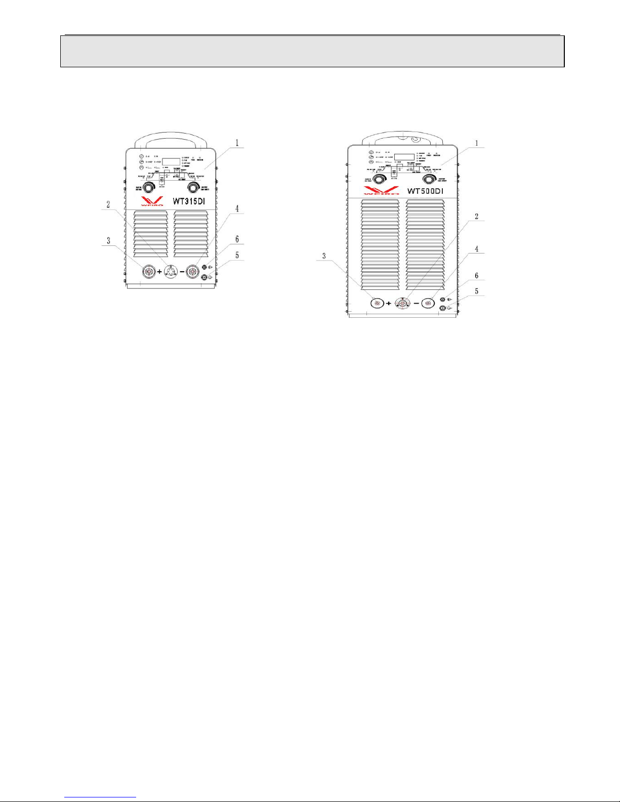
WT-DI series inverter multifunctional welding machines can be divided into three types (315DI, 500DI
and 630DI). They can perform DC constant current TIG welding, DC pulse TIG welding, square wave AC
constant current TIG welding, square wave AC pulse TIG welding, which are used for carbon steel, copper,
titanium, aluminum as well as aluminum-magnesium alloy welding. Because of reasonable static and sound
dynamic characteristic the welders enjoy, they have comprehensive operational functions.
Features and benefits:
◆Feature for AC/DC TIG welding, good looking weld, deep melting and low electrode consumption.
◆Self-diagnostic function with error code display.
◆HF soft switch transform, high efficiency, small size, light weight.
◆Multi-function, convenience, good adjustability.
◆Knob-control preset of all parameters and welding state, simple and convenient.
◆Excellent weld seam quality can be achieved due to its effect on all important areas of the weld.
◆Non-source power factor compensation technology, high PF (power factor).
◆Easy to arc-starting, stable arc, high performance.
◆Atype enjoys the synchronous mutual arc function.
◆Adjustable argon stopping time of lag, current descending time and the current of stopping arc improve
the TIG welding performance.
Applications:
◆Suitable for mild steel, Copper, Titanium, Aluminum and Al-Mg alloy welding.
◆Electric power, petrochemical Construction.
◆Boiler pressure container manufacture.
◆Shipyards.
◆Bicycle, fitness equipment, and stainless furniture manufacture.

-6-
Installation Guide
1.Pre-installation
1.1 Installation Environment
The WT-DI is designed for use in adverse environments. Examples of environments with
increased adverse conditions are:
In locations in which freedom of movement is restricted, so that the operator is forced to
perform the work in a cramped (kneeling, sitting or lying) position with physical contact with
conductive parts;
In locations which are fully or partially limited by conductive elements, and in which there is
a high risk of unavoidable or accidental contact by the operator;
In wet or damp hot locations where humidity or perspiration considerably reduces the skin
resistance of the human body and the insulation properties of accessories.
Environments with adverse conditions do not include places where electrically conductive
parts, in the near vicinity of the operator, which can cause increased hazard, have been
insulated.
The gradient of ground must be no more than 10°
Ensure no wind at the welding position, or use screen to block the wind.
The distance between welder and wall must be more than 20cm, between welders more than
10cm to ensure enough heat radiation.
When using water-cooled torch, must be care of not being frozen.
Welding power sources with degree of protection IP23S may be stored, but are not intended to
be used outside during precipitation unless sheltered.
1.2 Installation Location
Be sure to locate the welder according to the following guidelines:
In areas, free from moisture and dust.
Ambient temperature between 0 degrees C to 40 degrees C.
In areas, free from oil, steam and corrosive gases.
In areas, not subjected to abnormal vibration or shock.
In areas, not exposed to direct sunlight or rain.

-7-
1.3 Power Source Connections
Warning
Thermal Arc advises that this equipment be electrically connected by a qualified electrician.
ELECTRIC SHOCK can kill; SIGNIFICANT DC VOLTAGE is present after removal of
input power.
DO NOT TOUCH live electrical parts.
SHUT DOWN welding power source, disconnect input power employing lockout/tagging
procedures.
Lockout/tagging procedures consist of padlocking line disconnect switch in open position.
Removing fuses from fuse box, or shutting off and red-tagging circuit breaker or other
disconnecting device.
1.4 Power Supply Requirements
Input volt must be standard sine wave, effective value 380V±10%, and frequency 50Hz.
Unbalance degree of 3- phase volt must be no more than 5%
Power supply
Product type
315
500
630
Power supply
3 phase AC380V
Min. capacity
Power network
14KVA
27KVA
45KVA
Input volt
protection
Fuse
20A
40A
60A
Circuit breaker
40A
60A
100A
Cable size
(cross-section)
Input volt
4mm2
6mm2
10mm2
Output volt
35mm2
50mm2
70mm2
Ground lead
4mm2
6mm2
10mm2
Table 5: Power supply connection
Note: The sizes of fuse and breaker in the table are for reference only.

-8-
2. Installation:
The input power of this series welding machines is three phase AC 380V/50Hz. Operator must
use the properly disconnected switchboard or switch box(not provided by our company)
which is equipped circuit breaker, and should ground the welder safely and firmly.
Connect ground lead.
Connect terminal socket (+) to workpiece on AC/DC TIG, to stick holder cable on SMAW.
Connect TIG torch to terminal socket (-) on AC or DC TIG, connect socket (-) to workpiece on
SMAW.
Connect welder’s gas inlet to gas regulator by gas hose.
Connect TIG torch’s gas inlet to welder’s gas outlet.
Wire foot pedal switch or torch control cable to control cable socket.
When use water-cooled torch, connect water circulator to welder’s water inlet and torch’s
water inlet to welder’s water outlet.
Power on air switch on the welder’s rear panel.
Connect input power cable to switch box and power on.

-9-
Operating Instruction
1.Function introduction
1.1 Front panel illustration and parts number reference
Figure 6: Model WT315DI Figure 7: Model WT500DI/630DI
(1) Control panel
Set the welding parameters.
(2) TIG socket
Connect the TIG torch or foot pedal switch when processing TIG welding.
(3) Terminal socket (+)
Connect to electrode holder when in SMAW mode; Connect to the workpiece when in
TIG mode.
(4) Terminal socket (-)
Connect the workpiece in SMAW mode; connect to the TIG torch in TIG mode.
(5) Water outlet
(6) Gas outlet
Connect to TIG torch gas hose.

-10-
1.2 Foot pedal switch with adjustable welding current
Figure 8: Foot pedal switch
Foot pedal switch can be used for arc start control and welding current regulation of model 315.
Welder will switch automatically to foot pedal control after the control plug is connected to welder’s
control cable socket. When the pedal is stepped on, the welder begins to work at welding current in
line with the degree of the pedal being pressed.
1.3 Rear panel illustration and parts number reference
Figure 9: Model WT315DI Figure 10: Model WT500DI/630DI
(1) Circuit Breaker

-11-
The function of circuit breaker is to protect welding machine by automatic trip to cut the power
supply while in machine is during overload or failure. Use switch on the switch box to start or stop
welding machine. Don’t use this circuit breaker as power switch.
(2) Input power cable
It is 4-pin cable. The mixed-colored wire must be firmly grounded, the rest wires connect to
corresponding 3-phase power supply (380V 50Hz).
(3) Cooling fan
Used to cool down the components in the welding machine.
(4) Ground bolt
To ensure operators not to be harmed and welding machine to work normally, make sure the ground
bolt grounded firmly by ground cable, or make sure the ground wire (mixed-colored) of the input
power cable grounded firmly.
(5) Gas inlet (Part of electromagnetic valve)
Connect to Argon gas regulator with gas hose.
(6) Water inlet
(7) Specification Plate
(8) Warning mark

-12-
1.4 Control panel
The control panel is shown as Figure 7, which is used to select welder functions and to set up
parameters. The control panel is consisting of digital displayer, regulation knobs, and LED indication
lights.
Figure 11: Control panel
DC TIG/AC square wave TIG
2-step (Non-Auto lock) / 4-step (Auto lock)

-13-
Constant current TIG/Pulse TIG /SMAW

-14-
1.4.1 Glossary:
1. Pre-gas flow: Time elapse of gas flow before welding
2. Arc-start: Min current of start arc
3.Up-slope: Time elapse of welding current slopes up
4.Constant current: welding current on output constant current
5.Oxide clean ratio: time ratio of output clean current
While in AC TIG, regulate clean width and penetration to obtain optimum welding
quality.
Figure 12: Illustration for Oxide clean ratio
6. AC Bias: Ratio of clean current dividing by welding current.
By adjusting the parameter, as to adjusting clean current result in reasonable oxide clean effect.
Suggestion: At the same clean effect, reduce clean ratio and increase AC bias to obtain deeper
penetration, higher productivity and prolong tungsten electrode lifespan.
7. AC frequency: Frequency of output AC
8. Peak: Peak value of output pulse
9. Pulse ratio: Time ratio between length of peak value current and length of whole single pulse
applied in pulse TIG, can be easily used for controlling penetration in all-position or thin sheet
welding.
10. Pulse frequency: Output pulse frequency
11.Base current: Arc maintenance current of output pulse
Control panel
Consumption of
tungsten electrode
Wave form of
current
Clean effect
More
Less
Wide &shallow
Narrow &deep

-15-
12. Down –slope: Time of welding current slopes down
13. Crater filling: Welding current of crater filling.
14.Post-gas flow: Time of gas flow after ending welding
Figure 13: Parameters Setting Knob
Function selection knob: Used for shifting modes illustrated previously. Tuning
clockwise can select modes orderly from left to right, while select reversely by tuning
counter-clockwise.
Parameters preset knob: Used for adjusting the values of parameters. Increase by
tuning clockwise, reducing by tuning counter-clockwise. Press the knob and tune right or left for quick
adjustment.
Welder can automatically save the set-up for next use while turning off the machine
1.4.2 “Protection” indicator light: lights on yellow and the machine stops welding automatically
during overheat, over-current, over-voltage or water insufficient, but will not light on while in
normal welding. Protection codes are illustrated below:
1.Display 801: Over-voltage protection. Please turn off welder immediately and inform authorized
reseller to repair.
2.Display 802 or 803: Over-current protection. Please turn off welder immediately and inform
authorized reseller to repair.
3.Display 804: Overheat protection. Please turn off welder immediately to cool it down.
4.Display 805: Pulling torch trigger for a long time with no current or torch damaged. Repair
welding torch or foot pedal
5.Display 806 (500,630 types): Water insufficient protection. The default setting is “water cooled”. It
does work while using a water-cooled torch at normal water circulation. When applied air-cooled
torch, the welder’s protection light will light on and display “806” protection code. Press the
Function selection and parameter preset knobs simultaneously for up to 3 seconds to eliminate
water insufficient protection. Redo the same way to back to previous mode.
1.4.3 Power on/off light: It displays red when power on.

-16-
2. Suggested welding parameters setting:
Sheet/
plate
thickness
(mm)
Diameter
of
Tungsten
electrode
(mm)
Welding
current(A)
Wire
diameter
/mm
Argon flow
rate/L.min-1
Welding
layer
face/back
Preheat
temperature
Remark
1
2
40-60
1.6
7-9
Face 1
-
Flange
welding
1.5
50-80
1.6-2.0
Flange
welding or
single side
butt
welding
2
2-3
90-120
2-2.5
8-12
Butt
welding
3
3
150-180
2-3
V-shape
bevel butt
welding
4
4
180-200
3
10-15
1-2/1
5
180-240
3-4
6
5
240-280
4
14-16
1-2/1
8
260-320
4-5
2/1
100
10
280-340
3-4/1-2
100-150
12
5-6
300-360
16-20
150-200
14
340-380
5-6
180-200
16
6
4-5/1-2
200-220
18
360-400
200-240
20
20-22
200-260
16-20
340-380
16-22
2-3/2-3
22-25
6-7
360-400
20-22
3-4/3-4
Table 6: TIG welding parameters
Table 7: SMAW welding parameters
Workpiece
thickness
(mm)
<1
2
3
4~5
6~12
≥13
Welding
electrode
diameter
(mm)
1.5
2
3.2
3.2~4
4~5
5~6
Welding
current(A)
20~40
40~50
90~110
90~130
160~250
250~400

-17-
Repair& Maintenance
WARNING: Have a qualified electrician do the maintenance and trouble shooting work. Turn the input
power off, using the disconnect switch at the fuse box before working inside the machine.
1. Cautions:
Rivet equipment name tag on the specified area of the case, otherwise the inside parts will possibly
be damaged.
Connect welding cable to terminals firmly, otherwise the terminals will be burn out which will
cause the instability of welding process.
Avoid welding cable and control cable being broken, and prevent welding machine from being short
circuit.
Never let welding machine be bumped into or stacked up by heavy objects.
Ensure good ventilation
Under high temperature, if work with large current for long period, welder may shut down
automatically due to thermal protection acts .At this point, let the machine runs under open-load for
a few minutes, and it will be automatically recover.
Under high temperature, if work with large current for long period, welder may shut down
automatically due to air switcher trips. Cut off the power supply to the electricity switchboard on
frame, and wait for 5 minutes to turn on the air switcher on the power source fist then connect the
power supply to the electricity switchboard on frame. And leave the machine runs under open-load
condition for a while.
After welding, cut off the Argon gas supply and the power supply.
2. General maintenance
Remove dust from power resource with pressure air by qualified individuals every 3-6 months.
Check if the jointers are loose.
Check regularly if cables are worn out, knobs are loose, and components of panel are damaged.
Check regularly if cables are tightly connected to cable connecting terminals in case of terminals
being burnt out.
Clean and replace Contact Tip and Tungsten Electrode in time.
3. Procedure for regular checking prior to maintenance
Check if all front panel switches are on the proper positions.

-18-
Check if the input volt has the phase missing. (Input power 3 phase 380V/50HZ)
Check if the input cable is connected correctly and firmly with the power source.
Check if the ground lead is connected correctly and firmly.
Check if the welding cables are connected correctly and firmly.
Check if gas regulator is in good situation and gas flows out normally.
WARNING: Have a qualified electrician do the maintenance and trouble shooting work. Turn the input
power off, using the disconnect switch at the fuse box before working inside the machine. Don’t open up
case uninstructed, the max volt inside machine is 600V, Never discharge high voltage to welder case with
welding torch! Shut down power source before changing or repairing welding cable or torch.

-19-
№
TROUBLE
CAUSES
WHAT TO DO
1
Indicator light does
not light on and
doesn’t work when
machine switches on.
(1)Phase missing
(2)Fuse size(2A)breaks
(3)Input cable break down
(1)Inspect power source
(2)Inspect fan, transformer
for ZKB/QDB and
control board are in good
condition or not
(3) Inspect cable
2
Circuit Breaker trips
automatically while
welder working on
without big welding
current for long time
The following components
may probably damaged:IGBT
module, 3 phase rectified
module, output diode module,
and other components
Short circuit
(1) Inspect and replace
(2)When IGBT module
breakdown, check if
resistors 12Ω. 5.1Ωand
SR160 on driving board are
damaged or not.
3
Welding current is not
stable.
(1)Phase missing
(2)Main control board is
damaged.
(1) Inspect power source
(2) Inspect and replace
4
Welding current is not
adjustable.
(1) Conductive wire broken.
(2)Main control board is
damaged.
(3) Encoder is damaged
Inspect and replace
5
Display 801
protection code (over
voltage)
(1)Secondary IGBT module is
damaged
(2)Main control board is
Damaged
Replace secondary IGBT
module and main control
board
6
Display 802 or 803
protection code (over
current)
(1)Secondary IGBT module is
damaged
(2)Main control board is
damaged
Replace secondary IGBT
module and main control
board
7
Display 804
Protection code
(overheat)
(1)Welding current is too large
(2)Environmental temperature
is too high.
(3)Thermal switch is damaged
(1)Working in open load,
idle and cooling down
(2) Replace thermal switch
8
Display 805
protection code
(1)Torch trigger has been
pushed for a long time in
open load
(2)Welding torch trigger or
foot pedal switch is damaged
(1) Inspect the torch or foot
pedal switch and replace it
(2) Release the trigger
9
Display 805
protection code (water
insufficient)
(1) No water supply
(2) Bad water circulation
(3)Water valve, water
circulator or torch are
damaged
(1)Connect to water supply
(2)Inspect water circulation
(3)Replace the valve,
circulator or torch
Table 8: Trouble Shooting
Table of contents
Other Weiro Welding System manuals
Popular Welding System manuals by other brands

FRONIUS
FRONIUS VR 7000 Operating instructions/spare parts list

FRONIUS
FRONIUS MTG 270i US operating instructions

FRONIUS
FRONIUS DeltaSpot Series Operating instructions and spare parts list

gala gar
gala gar GALA TIG 3200 ACDC Quick installation guide

Elettro C.F.
Elettro C.F. PLASMA 473 instructions

Uni-Mig
Uni-Mig VIPER 120 SYNERGIC operating manual