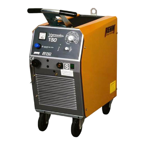
REHM SYNERGIC.PRO2 170-2 User manual

GB
OPERATING INSTRUCTIONS
MIG/MAG GAS-SHIELDED WELDING UNITS
SYNERGIC.PRO² 170-2 –600-4 WS

Product identification
MIG/MAG inert gas metal arc welding units
SYNERGIC.PRO2170-2 SYNERGIC.PRO² 350-4 W
SYNERGIC.PRO2190-2 SYNERGIC.PRO2350-4 S
SYNERGIC.PRO2230-2 AM SYNERGIC.PRO2350-4 WS
SYNERGIC.PRO2230-4 AM SYNERGIC.PRO2450-4
SYNERGIC.PRO2280-2 SYNERGIC.PRO2450-4 W
SYNERGIC.PRO2280-4 SYNERGIC.PRO2450-4 S
SYNERGIC.PRO2310-4 SYERGIC.PRO2450-4 WS
SYNERGIC.PRO2250-4 SYNERGIC.PRO² 500-4 S
SYNERGIC.PRO2300-4 SYNERGIC.PRO² 500-4 WS
SYNERGIC.PRO2300-4 S SYNERGIC.PRO² 600-4 S
SYNERGIC.PRO² 350-4 SYNERGIC.PRO² 600-4 WS
REHM GmbH u. Co KG
Ottostr. 2
73066 Uhingen, Germany
Telephone: 07161/3007-0
Fax: 07161/3007-20
Internet: http://www.rehm-online.de
Document number: 730 1815
Release date: 18.03.2014
Rehm GmbH u Co. KG, Uhingen, Germany 2006
The contents of this description is the sole property of Rehm GmbH u. Co. KG.
The disclosure or reproduction of this document, the sale and communication of
its content are prohibited unless expressly permitted.
Actions to the contrary will be subject to compensation. All rights are reserved in
the case of patent, utility patent or registered design.
Manufacture using these documents is not permitted.
Subject to change.
Designation
Type
Manufacturer

Contents
3
Contents
Product Identification……………………………………………………………………………………….. 2
1INTRODUCTION......................................................................................................................................6
1.1 Preface.................................................................................................................................................6
1.2 General description............................................................................................................................8
1.2.1 Performance characteristics of SYNERGIC. PRO2MIG/MAG inert gas metal arc welding units.9
1.2.2 Principle of the metal inert gas welding procedure .....................................................................10
1.2.3 Functioning principle of REHM SYNERGIC. PRO2welding units...............................................10
1.2.4 Correct use..................................................................................................................................10
1.3 Symbols used ...................................................................................................................................11
2SAFETY NOTES....................................................................................................................................12
2.1 Safety symbols used in these operating instructions..................................................................12
2.2 Warning symbols on the unit..........................................................................................................12
2.3 General ..............................................................................................................................................13
3FUNCTIONAL DESCRIPTION ..............................................................................................................14
3.1 Switching on .....................................................................................................................................14
3.2 Description of the operating elements...........................................................................................14
3.3 Control LEDs.....................................................................................................................................15
3.4 Function selection switch................................................................................................................15
3.4.1 Material thickness .........................................................................................................15
3.4.2 2-step function.............................................................................................................................16
3.4.3 4-step function.............................................................................................................................17
3.4.4 Spot function ......................................................................................................................17
3.4.5 Pulse function..............................................................................................................................18
3.5 Step switch........................................................................................................................................18
3.6 Automatic feed..................................................................................................................................18
3.7 Program selection ............................................................................................................................18
3.7.1 Gouging (only available with SynPro2 500 and 600).........................................................................19
3.8 SDI –steplessly controllable choke ...............................................................................................20
3.9 Automatic creep................................................................................................................................20
3.10 Automatic burn back function.........................................................................................................20
3.11 Gas post-purge time.........................................................................................................................20

Contents
4
3.12 Forced switch off............................................................................................................................ 20
3.13 Additional functions....................................................................................................................... 21
3.13.1 Water circulation cooling ............................................................................................................ 21
3.13.2 Temperature monitoring of power elements............................................................................... 21
3.13.3 Third party cooling of the power elements ................................................................................. 21
3.13.4 Fan and water pump operation................................................................................................... 21
3.13.5 Digital voltmeter and ammeter.................................................................................................... 21
3.13.6 REHM automatic threading ........................................................................................................ 22
4ACCESSORIES .................................................................................................................................... 23
4.1 Standard accessories...................................................................................................................... 23
4.2 Overview of options......................................................................................................................... 23
4.2.1 Wire feed case with trolley.......................................................................................................... 24
4.2.2 Intermediate hose bundles for SYNERGIC.PRO2...................................................................... 24
4.2.3 Torch connection........................................................................................................................ 24
4.2.4 Special voltages.......................................................................................................................... 24
4.2.5 Air filter attachment..................................................................................................................... 24
4.2.6 Crane lugs .................................................................................................................................. 24
5PUTTING INTO OPERATION............................................................................................................... 25
5.1 Safety notes...................................................................................................................................... 25
5.2 Working under increased electrical risks in accordance with the regulations of IEC 974,
EN 60 974-1, TRBS 2131 and BGR 500 Chapter 2.26 (previously known as VGB 15)............... 25
5.3 Setting up the welding unit............................................................................................................. 25
5.4 Connecting the welding unit........................................................................................................... 26
5.5 Cooling the welding unit................................................................................................................. 26
5.6 Water cooling for MIG/MAG welding torch.................................................................................... 26
5.7 Connecting the welding hoses....................................................................................................... 26
5.8 Connecting the torch....................................................................................................................... 27
6OPERATION......................................................................................................................................... 28
6.1 Safety notes...................................................................................................................................... 28
6.2 Checks before starting.................................................................................................................... 28
6.3 Connection of the earthing cable................................................................................................... 28
6.4 Switching on..................................................................................................................................... 29
6.5 Select mode...................................................................................................................................... 29
6.6 Set welding voltage ......................................................................................................................... 29
6.7 Set wire feed rate............................................................................................................................. 30

Contents
5
6.8 Gas post-flow time............................................................................................................................30
6.9 Practical notes..................................................................................................................................31
7FAULTS .................................................................................................................................................33
7.1 Safety notes ......................................................................................................................................33
7.2 Table of faults ...................................................................................................................................33
8REPAIRS AND MAINTENANCE...........................................................................................................36
8.1 Safety notes ......................................................................................................................................36
8.2 Maintenance table.............................................................................................................................36
8.3 Cleaning the inside of the unit........................................................................................................37
8.4 Cooling water and cooler inspection..............................................................................................37
8.5 Correct disposal ...............................................................................................................................37
9CIRCUIT DIAGRAMS............................................................................................................................38
10 COMPONENTS OF THE SYNERGIC.PRO2UNITS..........................................................................44
10.1 List of components with REHM Order numbers ...........................................................................44
11 SETTING OF CONTROL MODULE...................................................................................................57
12 TECHNICAL DATA............................................................................................................................58
13 INDEX.................................................................................................................................................59

Introduction
6
1 Introduction
1.1 Preface
Dear Customer,
You have purchased a REHM inert gas welding unit, a branded German
product We would like to take this opportunity to thank you for putting
your trust in our quality products.
Only components of the highest quality are used in the development and
manufacture of REHM SYNERGIC. PRO2 inert gas metal arc welding
units. In order to guarantee high durability, even under the toughest of
conditions, all REHM welding units contain components that live up to
strict REHM quality requirements. SYNERGIC. PRO2MIG/MAG inert gas
metal arc welding units have been developed and manufactured in
accordance with generally recognised safety and technical regulations. All
of the relevant legal requirements have been taken into account and are
supported by the conformity declaration and the CE mark.
REHM inert gas metal arc welding units are produced in Germany and
carry the "Made in Germany" quality mark.
Since REHM is constantly developing its products in line with technical
progress, we reserve the right to adapt and modify this welding unit at any
time, in order to meet the latest technical requirements.

Introduction
7
REHM welding units are, unless explicitly permitted in writing by REHM; only for
sale to commercial and industrial users and only for use by such.
SYNERGIC.PRO2MIG/MAG inert gas metal arc welding units should only be used
for the specified uses
in a safe state
REHM welding units may only be operated and maintained by persons who have
been educated and trained to operate and maintain welding units. Only qualified,
authorised and trained staff may work on and with the equipment.
These operating instructions contain important notes regarding how to operate this
unit safely, correctly and economically. A copy of the operating instructions should
always be kept on site in a suitable location. Please make sure that you read the
information summarised in this operating manual before using the equipment. It
contains important notes regarding use of the device which enables you to fully use
the technical advantages of this REHM devices. In addition, you will also find
information regarding maintenance and upkeep of the units as well as the
operational and functional safety.
These operating instructions do not replace instructions given by REHM's service
personnel.
The documentation for any additional options must also be taken into
consideration.
Changes to the unit or the addition or installation of further elements is not
permitted. This would invalid the guarantee and warranty claims.
Any third-party changes or deactivation of the safety mechanisms renders all
guarantee claims invalid.
Areas of use
Qualifications of the
operating personnel
Purpose of the
document
Changes to
the unit

Introduction
8
1.2 General description
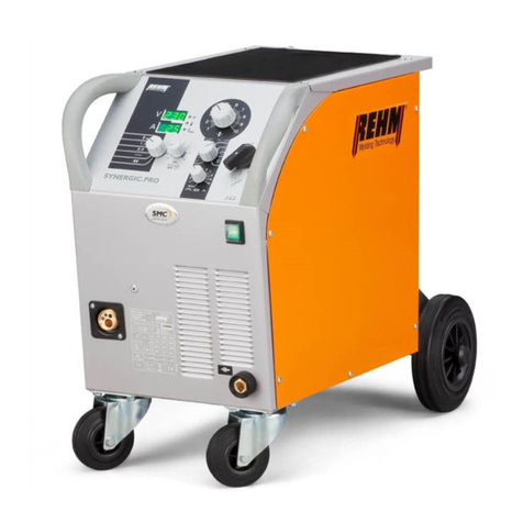
Diagram 1 SYNERGIC.PRO2230-4 , SYNERGIC.PRO² 350-4 WS
(picture similar)

Introduction
9
1.2.1 Performance characteristics of SYNERGIC. PRO2
MIG/MAG inert gas metal arc welding units
REHM SMC (Smart Machine Control)
The integrated systems and regulatory mechanisms of the Smart Machine
Control (SMC) react effectively, at all times, to changes in the arc, and also
constantly control the droplet transfer. SMC summarizes all user settings,
characteristic curve definitions, target value settings and actual value
measurements, evaluates them and coordinates the regulator actions in
accordance with the routines defined by the welding experts
REHM SDI (Stepless Dynamic Induction)
The REHM-SDI provides the SYNERGIC. PRO2with a choke which is
electronically and steplessly controlled, thus guaranteeing excellent ignition
characteristics and an even more stable arc.
REHM RSC (Realtime Speed Control)
The incremental rotary encoder is used to monitor the feed rate directly at the
motor. This ensures that changes in the arc length can be recognised and
corrected as early as possible. RSC guarantees reproducible, constant wire
feed rates –regardless of motor temperature or dirty hose bundles.
REHM CCM (Characteristic Curve Memory)
CCM makes it extremely easy to operate the SYNERGIC.PRO2 . The
comprehensive, integrated welding parameter database (CCM) is filled with
the knowledge of experts with many years of practical experience. The
combination of material, wire diameter and voltage level is used to pre-select
the synergy parameters required for a successful welding process. During the
welding process, the actual values are constantly compared to the process
specifications and corrected immediately when required.
REHM housing form design
Increased ergonomics thanks to the constant further development of the
REHM design. The protected and well thought out construction achieves the
IP23 protection class. This enables welding outside.
REHM Industrial control
Mains voltage is permanently monitored for fluctuations and compensated
appropriately, ensuring optimum, uniform welding results. The 2-step and 4-
step modes, spot and pulse function, digital voltmeter and ammeter, and
display of material thickness, are installed as standard features.
REHM automatic creep
The unit reduces the wire feed rate until the arc has ignited. This ensures a
safe ignition process.
REHM automatic burn back
Ensures that the user has a constant wire end length when they complete the
welding process.
REHM automatic threading
Adjusted wire feed rate during threading.
Powerful 2/4 roller wire feed drive
Both the 2 and 4 roller drives guarantee safe wire feeding, even when used
with torches with excess length.
Introduction
10
1.2.2 Principle of the metal inert gas welding procedure
During the metal inert gas welding process, the arc burns between a melting wire
electrode and the work piece. Argon, carbon dioxide (CO2) or a mix of these or
other gases are used as the inert gas.
The wire electrode is unwound from a spool by a feed motor and pushed through
the torch bundle to the contact tip.
The positive pole of the current source is attached to the current contact nozzle,
to the wire electrode and the negative pole on the work piece. An arc is formed
between the wire electrode and the work piece which melts the wire electrode
and fuses it to the work piece. The electrode is thus both arc carrier and welding
material at the same time.
The wire electrode and the pool crater are protected from the oxygen in the air by
the inert gas that is released from the nozzles which are arranged concentrically
around the electrode.
1.2.3 Functioning principle of REHM SYNERGIC. PRO2
welding units
REHM inert gas metal arc welding units are MIG/MAG constant voltage sources
with the welding voltage adjusted by step switches. The wire speed is determined
automatically by the pre-selected welding voltage. A correction knob to set the
wire speed precisely is used to control the individual arc length.
Alloyed and non-alloyed steel, stainless steel and aluminium and galvanised
sheet can be welded (MIG brazing) with REHM -SYNERGIC.PRO2 inert gas
metal arc welding units.
These units are designed for optimum welding performance and high efficiency,
are equipped with robust housings and feature cooling systems designed for
minimum noise output. All the components have been extensively tested under
practical conditions for heavy-duty and industrial usage.
1.2.4 Correct use
REHM welding units are designed to be used to weld various metals such as
non-alloyed and alloyed steel, stainless steel and aluminium. You should also
pay attention to the special regulations pertaining to your area of application. If
anything is unclear, consult your safety officer or contact REHM's customer
service department.
REHM welding units are, unless explicitly permitted in writing by REHM; only for
sale to commercial and industrial users and only for use by such. They may only
be operated by persons trained in the use and maintenance of welding units.
Welding current sources may not be set up in areas with increased electrical risk.
These operating instructions contain rules and guidelines for the correct use of
your unit. Only when these are adhered to can it be described as correct use.
Risks and damages caused as a result of a different type of use is the
responsibility of the operator. In the event of special requirements, it may be
necessary for additional special conditions to also be taken into account.
If anything is unclear, consult your safety officer or contact REHM's customer
service department.

Introduction
11
You should also pay attention to the special notes regarding correct use as set
out in the delivery documentation.
National regulations regarding the operation of the unit are valid with no
restrictions .
Correct use also covers the observation of the correct measures with regard to
mounting, removal and remounting, taking into service, operation and
maintenance as well as disposal.
Please heed, in particular, the information in the safety instructions chapter.
The unit may only be operated under the conditions set out above. Any other use
is not correct. The consequences are the responsibility of the operator.
1.3 Symbols used
Lists with bullets: General lists
Lists with a square: Work or operational steps that much be carried out
in the sequence listed.
Chapter 2.2, Warning symbols on the unit
Cross-references: In this case, to Chapter 2.2 Waning symbols on the unit
Bold is used for emphasis
Note!
... Indicates user tips and other particularly useful information.
The safety symbols used in this manual: Chapter 2.1.
Typographic
symbols
Safety
symbols

Safety notes
12
2 Safety notes
2.1 Safety symbols used in these operating
instructions
This or a symbol more specific to the danger can be found with all safety
notes in these operating instructions which carry a risk to life and limb.
One of the following signalling words (Danger! Warning! Caution!)
indicates the degree of danger:
Danger! ... indicates immediate threat of danger.
If this is not avoided it may lead to death or serious injury.
Warning! ... indicates a potentially dangerous situation.
If this is not avoided it may lead to death or serious injury.
Caution! ... indicates a situation in which damage may occur.
If this is not avoided it may lead to slight or minor injuries and damage to
property.
Important!
Indicates a potentially damaging situation. If this is not avoided it may lead
to damage to the product or to something in the vicinity.
Materials that may be hazardous to health or environment.
Materials that must be treated/disposed of in accordance with the law.
2.2 Warning symbols on the unit
indicate hazards and sources of danger on the equipment.
Danger!
Dangerous electrical voltage!
Ignoring may lead to death or injury,
Warning notes and
symbols

Safety notes
13
2.3 General
The unit has been developed and constructed in accordance with recognised
technical knowledge.
However, using the unit may hold dangers for the life and limb of the user or third
parties or influence the unit or cause damage to other property.
None of the safety measures may be removed or put out of action, as this causes
risks and correct use of the unit cannot be guaranteed. Removing the safety
features during set up, repairs and maintenance is described separately. As soon
as this work is completed, the safety features must be replaced.
When using additional products (for example, solution for cleaning) the operator
of the unit is to ensure that the unit is safe for the product to be used.
All safety and danger notes as well as the type plate on the unit are to be
maintained, kept in a readable state and observed.
Safety notes serve to protect when working and to prevent accidents . They
must be observed.
The safety notes listed in this chapter must be observed along with the special
notes made in running text.
In addition to the instructions in these operating instructions, general safety and
accident prevention regulations (in Germany including UVV BGV A3, TRBS 2131
and BGR 500 Chapter 2.26 (formerly VGB15): "Welding, cutting and associated
processes" and in particular the references to arc welding and cutting and the
appropriate national regulations) must be observed.
Please also note the safety notices in the workplace of the operator.
High performance units may affect the main power supply thanks to their high
power consumption. For certain units types, there may be connection
restrictions, requirements regarding the maximum permitted net impedance or
requirements regarding the minimum required available power at the point of
connection to the main power supply (see Technical data) In these casese, the
user of such a unit must ensure, if necessary by consulting the power suppliers,
whether the unit may be connected.
Dangers of non-
observation
Safety instructions
Requirememts
made of the power
supply

Functional description
14
3 Functional description
3.1 Switching on
The main switch on the SYNERGIC.PRO2 is used to activate the main power.
The MAINS ON control lamp comes on. The upper digital display for welding
voltage shows the software version number (e.g. "P1.0") and the lower display
for welding current shows the data record number for the arc (e.g. " d0.1"). After
this, the upper display shows the machine type (e.g. "450" for a
SYNERGIC.PRO2 450-4 and the lower displays shows "on". The welding unit is
now ready to operate.
3.2 Description of the operating elements
1
2
345678
9
10
AutoSDI
109
8
7
6
5
4
3
21
SYNERGIC.PRO
450-4
7301630A
Al
1,0
1,2
1,2
1,0
0,8
Fe / CrNi
10
98765
4
3
2
1
3
2
1
7
2
6
108
11
12
3
9
145
Diagram 2:1 Correction knob for wire feed rate
2 Function selector switch for
- Material thickness (welding not possible in this position)
-2-step
-4-step
-Spots
-Pulse
3 Control lamp for OPERATION
4 Control lamp for TEMPERATURE
5 Control lamp for MATERIAL THICKNESS
6 Digital display for welding voltage or no-load voltage
7 Digital display for welding current or material thickness
8 Knob for setting spot and pulse time
9 Selector switch for program selection
10 SDI, steplessly controllable choke
11 Coarse step switch
12 Fine step switch

Functional description
15
3.3 Control LEDs
Control lamp
Location
Colour
Functions
MAINS ON
in the mains
switch
Green
Power supply voltage applied,
control on.
OPERATION
on control panel
Green
The no-load voltage is available
at the wire electrode. The
electrode is pushed out of the
contact tip of the torch. The arc
is ignited when the workpiece is
touched.
TEMPERATURE
on control panel
Yellow
The welding current is switched
off when the maximum
operating temperature of the
power components has been
exceeded. After it has cooled
down, the unit is automatically
switched back to operating
mode.
MATERIAL
THICKNESS
on control panel
Green
With the switch set to “material
thickness”, the material
thickness is shown on the
digital display
3.4 Function selection switch
3.4.1 Material thickness
The material thickness function allows rapid selection of the correct step switch
suitable for the welding job in question.
To do this, the processor controller accesses the characteristic curves stored on
the machine and displays the material thickness of the workpiece as determined
using the settings for material type, wire diameter (see Diagram 2 Selector switch
for program selection), wire feed rate and the step switch.
The digital displays (see Diagram 2) show when this function is selected the no-
load voltage and the material thickness. (see Chapter 3.13.5)
Sequence of material thickness function
Program selection
The program selection switch (see Diagram 2) is used to set the material type
and the wire diameter.
Press the torch button
No-load voltage is applied, wire feed is switched off.
The upper digital display shows the value of the no-load voltage
The lower digital display shows the suggested material thickness resulting
from the other machine settings selected

Functional description
16
Set step switch
Turning the step switch changes the no-load voltage and hence also the
subsequent welding voltage.
The material thickness shown in the lower digital display changes accordingly.
Set the step switch so that the material thickness corresponds to the welding
job in question.
Release torch button and select welding function
When the torch button is released, voltage is no longer applied at the outlet.
With the function selector switch (see Diagram 2) the function required for
welding –2-step, 4-step, spot or pulse –can be selected.
Welding is not possible when the function selection switch is set to the
material thickness function.
The material thickness cannot be displayed when the selection switch for
program selection is set to manual (since the material thickness is
dependant on the material type and the wire diameter and both of these are
not specified when using the manual setting).
While the torch button is pressed, no-load voltage is applied to the welding
wire. Ensure that you do not touch the free wire end and that there is no
contact to conductive materials.
The characteristics have been set for horizontal (position PB), one-sided fillet
welds. For other weld types or welding positions, it may be necessary to adjust
the power (step switch) and/or the feed rate to obtain your preferred setting.
3.4.2 2-step function
2-step welding is recommended for fast, controlled affixing and manual spot
welding.
How the 2-step function works:
1. Step –Press torch button
Magnet valve for inert gas is opened.
Welding voltage is applied
Wire feed starts at reduced speed
(automatic creep)
Arc is ignited, the welding current flows
Feed switches over to the set wire feed rate.
2. Step –Release torch button
Wire feed stops
Welding current is switched off after the burn back time has expired
The inert gas is switched off after the gas post flow time has elapsed.

Functional description
17
3.4.3 4-step function
The 4-step welding function is suitable for longer welds.
How the 4-step function works:
1. Step –Press torch button
Magnet valve for inert gas is opened.
Welding voltage is applied
Wire feed starts at reduced speed
(automatic creep)
Arc is ignited, the welding current flows
Feed switches over to the set wire feed rate.
2. Step –Release torch button
After the arc has been successfully ignited:
welding process continues without any changes
If the arc has not been ignited within 3 seconds, the unit automatically
switches back to the basic situation (safety shut-down)
3. Step –Press torch button
Wire feed stops
Welding current is switched off after the burn back time has expired
The inert gas is switched off after the gas post flow time has elapsed.
The length of time the gas continues to flow can be increased by holding
the torch button down
4. Step –Release torch button
Unit is ready for a new welding process
3.4.4 Spot function
The spot function enables precisely-timed spot welding, e.g. for consistent
tacking. Once the torch button has been pressed, the welding process is ended
automatically by the processor control once the pre-set spot time has expired.
The spot time can be freely selected using the rotary knob provided (see
Diagram 2).
How the spot function works:
Press the torch button
Magnet valve for inert gas is opened.
Welding voltage is applied
Wire feed runs at reduced speed (automatic creep feed)
Arc is ignited
Feed switches over to the set wire feed rate.
The spot time pre-set expires
When the set spot time is completed, the current source is deactivated
automatically.
Gas flows as long as the torch button is pressed.
Release the torch button
The inert gas is switched off after the gas post flow time has elapsed.
Releasing the torch button during the spot time ends the welding process
immediately and switches off the inert gas after the gas post flow time is
completed.

Functional description
18
3.4.5 Pulse function
The pulse function permits precisely-timed pulse welding, e.g. for reduced heat
input when welding thin sheets. While the torch button is pressed, the processor
control automatically switches welding on and off. The on time can be freely
selected using the rotary knob provided (see Diagram 2). The pause time is in
each case half as long as the on time.
Sequence of pulse function:
Press the torch button
Magnet valve for inert gas is opened.
Welding voltage is available
Wire feed starts at reduced speed
(automatic creep)
Arc is ignited
When welding begins, the wire feed is switched on for the set time
After this time has expired, the feed stops for the duration of the set pause
time. The wire feed is then re-activated etc.
Release torch button to end the welding process
Wire feed stops
Welding current is switched off after the burn back time has expired.
Inert gas is switched off after the gas post-flow time has expired.
3.5 Step switch
The welding voltage required is set using the step switch.
The various types of unit offer different voltage steps which you will find under
Chapter 12, Technical data.
3.6 Automatic feed
A specific wire feed rate is set for the wire feed motor by the step switch. The
"wire feed" potentiometer is used to fine tune in accordance with the material
used, the wire diameter and the inert gas. After this adjustment, the same setting
can be used to weld in several voltage steps, as the wire feed is automatically
adjusted.
3.7 Program selection
The REHM program selection function enables you to immediately set your
SYNERGIC.PRO2unit to the required welding task, without carrying out time-
consuming tryouts, simply by presetting the material type and the wire diameter.
The wire feed rate, the choke setting and the start and end phases are optimally
adjusted to the respective welding job electronically. To do this, the
SYNERGIC.PRO2 stores characteristic curves which determine the allocation of
these values to the material type set, to the wire diameter and to the welding
voltage constantly measured during welding. In addition, the material thickness
function (see Chapter 3.4.1) can be used to ascertain the suitable step switch
setting.

Functional description
19
The correction knob for wire feed rate (see Diagram 2) should be set to 5 for
steel and aluminium, and to 6.5 for CrNi.
If the selector switch for program selection is set to manual, these characteristic
curves are not used. The most suitable setting of the machine (including wire
feed rate, step switch) can be set by the user himself over the entire range.
The characteristic curves have been set for horizontal (position PB), one-sided
fillet welds. For other weld types or welding positions, it may be necessary to
adjust the voltage (step switch) and/or the feed rate.
3.7.1 Gouging (only available with SynPro2 500 and 600)
1. The program selection switch is switched to the "gouging" position.
2. On the rear wall:
The intermediate hose bundle is unplugged and the welding current
cable of the gouging torch is plugged in,
Remove the 16-pin plug and plug in the short circuit plug,
Caution! When the short circuit plug is plugged in, there
is output voltage available!
Please ensure that either the water hoses of the torch remain
connected, or a water bridge is specifically connected!
3. The "Operation" LED lights up, the protection is activated and the output
voltage is displayed.
4. The motor, the gas valve and the SDI are out of operation.
5. The function switch is not evaluated.
6. As soon as the output current starts to flow, the current value is also
displayed,
7. To switch back to welding operation, carry out points 1-2 in reverse order.
This means:
Unpulug the short circuit plug and plug in the 16-pin plug,
Unplug the welding current cable of the gouging torch and plug in the
intermediate hose bundle.
The program selection switch must be switched to the required welding
program.
Recommended settings with the carbon electrode 8 mm and "+" pole
Unit type
Program
Stage
Wprking pressure
Current ca. A
SynPro² 500
Manual
3-7
7 bar
400
SynPro² 600
Fe 1.6
3-1
7 bar
400

Functional description
20
3.8 SDI –steplessly controllable choke
All SYNERGIC.PRO2 units are equipped with an electronically controllable choke.
The throttle characteristics are dynamically adapted by the processor controller
to the relevant task. As a result, the optimum adjustment of the choke is set,
taking into account the material selection made when welding is started and
during welding.
The SYNERGIC.PRO2also offers the opportunity to adapt this choke effect to
suit the users' style and thus making the arc harder or softer. When the rotary
knob SDI (see Diagram 2) is at the left-hand stop (switch setting Auto), the
function is set to automatic and the choke has the soft arc setting recommended
by the manufacturer for every material selected. By turning the rotary knob to the
right, the arc can be set increasingly harder.
3.9 Automatic creep
Safe ignition is guaranteed by the automatic creep function. This reduces the
wire feed rate when the wire end is cold. After igniting the arc, the system
switches to the preset wire feed rate. Individual adjustment of the creep speed is
possible by modifying the "creep speed" potentiometer (see Chapter 11, R60) on
the circuit board (this can only be carried out by an authorised expert and
requires the unit to be opened).
3.10 Automatic burn back function
An appropriate burn back time is automatically set to match the wire feed rate
depending on the motor brake phase. Individual adjustment of the burn back time
is possible by modifying the "burn back time" potentiometer (see Chapter 11,
R59) on the circuit board (this can only be carried out by an authorised expert
and requires the unit to be opened).
3.11 Gas post-purge time
The gas post-flow time is set to 0.2 s as standard. The gas post-flow time can be
adjusted by up to 5 seconds by modifying the "post-flow gas" potentiometer (see
Chapter 11, R61) on the circuit board (this can only be carried out by an
authorised expert and requires the unit to be opened).
3.12 Forced switch off
If the welding process is not started within 3 seconds while pressing the torch
button, the welding voltage is switched off automatically in 4-step operation with
models SYNERGIC.PRO² 170-450 and in 2-step or 4-step operation with models
SYNERGIC.PRO² 500/600. If the welding current is interrupted for more than 3
seconds during welding in 2-step or 4-step operation, then the welding voltage is
switched off automatically with all models.
The machine is thus put into the basic state. This provides the user of REHM-
SYNERGIC.PRO2 units additional protection from electrical voltages and fire, as
standard.
This manual suits for next models
1
Table of contents
Other REHM Welding System manuals

REHM
REHM FOCUS.ARC P 300 User manual

REHM
REHM SYNERGIC.PRO 251 How to use

REHM
REHM BOOSTER2 130 Supplement

REHM
REHM TIGER 170 DC User manual

REHM
REHM TIGER DIGITAL 230 AC/DC ULTRA User manual

REHM
REHM TIGER 180 AC/DC ULTRA User manual

REHM
REHM FOCUS.ARC P Series How to use

REHM
REHM Tiger 170 User manual

REHM
REHM TIG.STAR 170 DC User manual

REHM
REHM SYNERGIC.ARC 251 User manual