manuals.online logo
Brands
  1. Home
  2. •
  3. Brands
  4. •
  5. Weka
  6. •
  7. Outdoor Storage
  8. •
  9. Weka 505.1414.00.00E Operating instructions

Weka 505.1414.00.00E Operating instructions

This manual suits for next models

2

Other Weka Outdoor Storage manuals

Weka 663.2409.00.00 Operating instructions

Weka

Weka 663.2409.00.00 Operating instructions

Weka 100.2030.00.10 User manual

Weka

Weka 100.2030.00.10 User manual

Weka 663.1303.00.00 Operating instructions

Weka

Weka 663.1303.00.00 Operating instructions

Weka 607.0602.00.00 Operating instructions

Weka

Weka 607.0602.00.00 Operating instructions

Popular Outdoor Storage manuals by other brands

LIVING AND HOME 0735940285711 user guide

LIVING AND HOME

LIVING AND HOME 0735940285711 user guide

USP DURAMAX 10 Ft x 8 Ft StoreMax Plus owner's manual

USP

USP DURAMAX 10 Ft x 8 Ft StoreMax Plus owner's manual

rollaway container ARPCA24 manual

rollaway container

rollaway container ARPCA24 manual

Duratuf GL105 Assembly instructions

Duratuf

Duratuf GL105 Assembly instructions

Viking SD5300SS Use & installation guide

Viking

Viking SD5300SS Use & installation guide

USP DURAMAX Apex Pro 10.5 Ft x 8 Ft 40116 owner's manual

USP

USP DURAMAX Apex Pro 10.5 Ft x 8 Ft 40116 owner's manual

ModuLaro Lojo WC202200 manual

ModuLaro

ModuLaro Lojo WC202200 manual

Outdoor Life Products FP2030 F Assembly instructions

Outdoor Life Products

Outdoor Life Products FP2030 F Assembly instructions

Royalcraft Faro 295L Storage Box Assembly instructions

Royalcraft

Royalcraft Faro 295L Storage Box Assembly instructions

TYGO Nyland Building Instruction

TYGO

TYGO Nyland Building Instruction

Riverlea Duratuf KIWI KS3 Assembly instructions

Riverlea

Riverlea Duratuf KIWI KS3 Assembly instructions

Rubbermaid 5L45 manual

Rubbermaid

Rubbermaid 5L45 manual

garofalo TUSCANY EVO user manual

garofalo

garofalo TUSCANY EVO user manual

OLT GS84D-FJ-Plywood Assembly manual

OLT

OLT GS84D-FJ-Plywood Assembly manual

Lifetime 6418 owner's manual

Lifetime

Lifetime 6418 owner's manual

Palram CANOPIA RUBICON 6x10 How to assemble

Palram

Palram CANOPIA RUBICON 6x10 How to assemble

Duratuf Havelock Assembly instructions

Duratuf

Duratuf Havelock Assembly instructions

Keter DUOTECH HIGH-STORE+ user manual

Keter

Keter DUOTECH HIGH-STORE+ user manual

manuals.online logo
manuals.online logoBrands
  • About & Mission
  • Contact us
  • Privacy Policy
  • Terms and Conditions

Copyright 2025 Manuals.Online. All Rights Reserved.

Montage-, Bedienungs- und
Wartungsanleitung
Art.-Nr.: 505.1414.00.00E
Art.-Nr.: 505.1414.10.00E
Art.-Nr.: 505.1414.20.00E
Stand: 1324
en ASSEMBLY, USER AND MAINTENANCE INSTRUCTIONS
fr NOTICE DE MONTAGE, D'UTILISATION ET D'ENTRETIEN
it ISTRUZIONI DI MONTAGGIO, USO E MANUTENZIONE
Technische Änderungen vorbehalten! 1© Copyright HRB 3662
- de -
Sehr geehrte Kundin, sehr geehrter Kunde,
danke, dass Sie sich für ein weka – Produkt entschieden haben.
Lesen Sie diese Anleitung vor dem Aufbau bitte vollständig durch, um Montagefehler oder
Beschädigungen zu vermeiden.
WICHTIG !
Prüfen Sie bitte sofort anhand der Packliste, ob das weka -Produkt vollständig
und unbeschädigt bei Ihnen angekommen ist.
Bitte vernichten Sie die Packliste erst nach Ablauf der Garantiezeit. Diese Liste dient Ihnen zur Kontrolle
auf Vollständigkeit der Einzelteile und ist mit dem Kaufbeleg aufzubewahren. Eventuelle Beanstandungen
können mit Hilfe dieser Liste problemlos behoben werden. Die Pos.-Nummern der Packliste stimmen nicht
mit den Pos.-Nummern folgender Montageanleitung überein.
Wir empfehlen Ihnen, die Montage mit 2 Personen durchzuführen.
Zur Verhütung von Unfällen ist zu vermeiden, dass sich Kinder während der Montage in unmittelbarer Nähe
befinden.
Weiterentwicklungen im Sinne des technischen Fortschritts behalten wir uns vor.
So können geringfügige Abweichungen in den Darstellungen entstehen.
Verpackungsmaterial nicht einfach wegwerfen! Papier-, Pappe- und Wellpappeverpackungen,
sowie Kunststoffverpackungsteile sollten in die entsprechenden Sammelbehälter gegeben werden.
Werkstoff Holz
Gesunde Äste, leichte Verfärbungen und kleine Risse sind für Holz charakteristisch, verleihen der Kabine
sein natürliches Aussehen und sind kein Reklamationsgrund.
Vor der Montage
Für das Aufstellen der Kabine wird eine Mindestraumhöhe von 205 cm benötigt.
Der Wandabstand muß mindestens 10 cm betragen.
Der Fußboden muss eben und waagerecht sein, da es sonst zu Funktionsstörungen kommen kann.
Am besten eignet sich ein trockener, gut belüftbarer Raum zur Nutzung Ihrer Kabine.
Ein Stein- oder Fliesenboden erweist sich als praktische und zugleich attraktive Fußbodenvariante.
Bei abweichendem Bodenbelag ist eine Steinplatte mit den Mindestmaßen 40 x 50 cm unter den Ofen zu
legen, um Beschädigungen des Bodens zu vermeiden.
Tipps zur Sicherheit
Achten Sie darauf, dass sich keine Kinder unbeaufsichtigt in der Kabine aufhalten!
Legen Sie keine Gegenstände auf dem Saunaofen ab. - BRANDGEFAHR !
Vergewissern Sie sich bereits vor Beginn der Heizphase, dass sich keine brennbaren Gegenstände in der
Nähe des Ofens befinden.
Verwenden Sie Sauna - Aufgusskonzentrate nur in verdünnter Form. Hinweise über die richtige
Handhabung finden Sie auf den Behältern.
Verwenden Sie keine chemischen Klebstoffe im Inneren der Sauna, sondern allenfalls Holzleim.
Nach Nutzung der Sauna lassen Sie diese bei geöffneter Tür auskühlen. Sorgen Sie stets für eine gute
Durchlüftung des Raumes, in dem sich die Sauna befindet.
Das Hinweisschild ist gut sichtbar in der
Nähe des Saunaofens zu befestigen.
Pflegehinweise
Die Wandschalung im Innenraum darf nicht abgedeckt werden oder mit Feuchtigkeit in Berührung kommen.
Nach der Nutzung der Kabine lassen Sie diese bei geöffneter Tür auskühlen.
Sorgen Sie stets für eine gute Durchlüftung des Raumes, in dem sich die Kabine befindet.
Bei längerer Nichtbenutzung empfehlen wir, die Kabinentür offen zu halten.
Hartnäckige Schmutzeinwirkungen auf dem Holz können mit Schmirgelpapier entfernt werden.
Elektroinstallation
Die Elektroinstallation darf nur von einem zugelassenen Elektrofachmann unter Beachtung der
VDE-und EVU-Richtlinien ausgeführt werden.
Hinweise zur Montage des Saunaofens und des Steuergerätes entnehmen Sie bitte den dort beiliegenden
Montageanleitungen.
Technische Änderungen vorbehalten! 2© Copyright HRB 3662
Empfehlungen zum Aufbau
Bitte bohren Sie alle Schraubverbindungen vor,
um Beschädigungen an den Holzteilen zu vermeiden!
Folgendes Zeichen macht Sie während der Anleitung
nochmals darauf aufmerksam:
Allgemeiner Aufbau der Wandelemente
Die Abbildung zeigt den
Schnitt durch ein
Wandelement mit beidseitiger
Profilholzschalung.
Alle Wandelemente sind mit
einer Dampfsperre und einer
Wärmedämmung ausgestattet.
Die Dampfsperre muss sich
nach Montage der Sauna immer
direkt hinter der Innenschalung
befinden.
Die Innenseite der Wandelemente
ist auf den Rahmenhölzern durch
einen Stempel-Aufdruck
innen gekennzeichnet.
Achten Sie deshalb vor dem Aufstellen der
einzelnen Elemente darauf, daß sich die
Nutseite (von außen gesehen) immer links befindet !
In die Wandelemente sind Befestigungshölzer für die Liegenhalterungen eingearbeitet.
Diese befinden sind ca. 36cm und 80 cm über dem Boden.
Die Lage dieser Hölzer erkennen Sie an den sichtbaren Schraubenköpfen im Elementrahmen.
Achten Sie darauf, daß sich diese Schraubenköpfe
beim Aufstellen jedes Wandelementes in der unteren
Elementhälfte befinden !
Vorbereitung des Wandelementes zur Montage der Multifunktions – Steuerung
Zur Montage der Bedieneinheit muss die
Öffnungshöhe im Wandelement 10 cm betragen.
Dazu schieben Sie das bewegliche Profilbrett und
die Kunststoffrohre nach oben heraus und kürzen
Brett und Rohre entsprechend.
ACHTUNG: Dies ist unbedingt
VOR dem Aufstellen des Wandelementes
durchzuführen!
R1-R5: Diese dienen als Montagerohre für
die Elektrokabel der Netzzuleitung, der Saunalampe
und des Saunaofens, ausgehend vom Steuergerät.
R1 + R4: für Leitung vom Modul Ofensteuerung
zum Saunaofen
R2 : für Leitung vom Modul Ofensteuerung
zur Bedieneinheit
R3 : Reserve
R5 : Reserve
Technische Änderungen vorbehalten! 3© Copyright HRB 3662
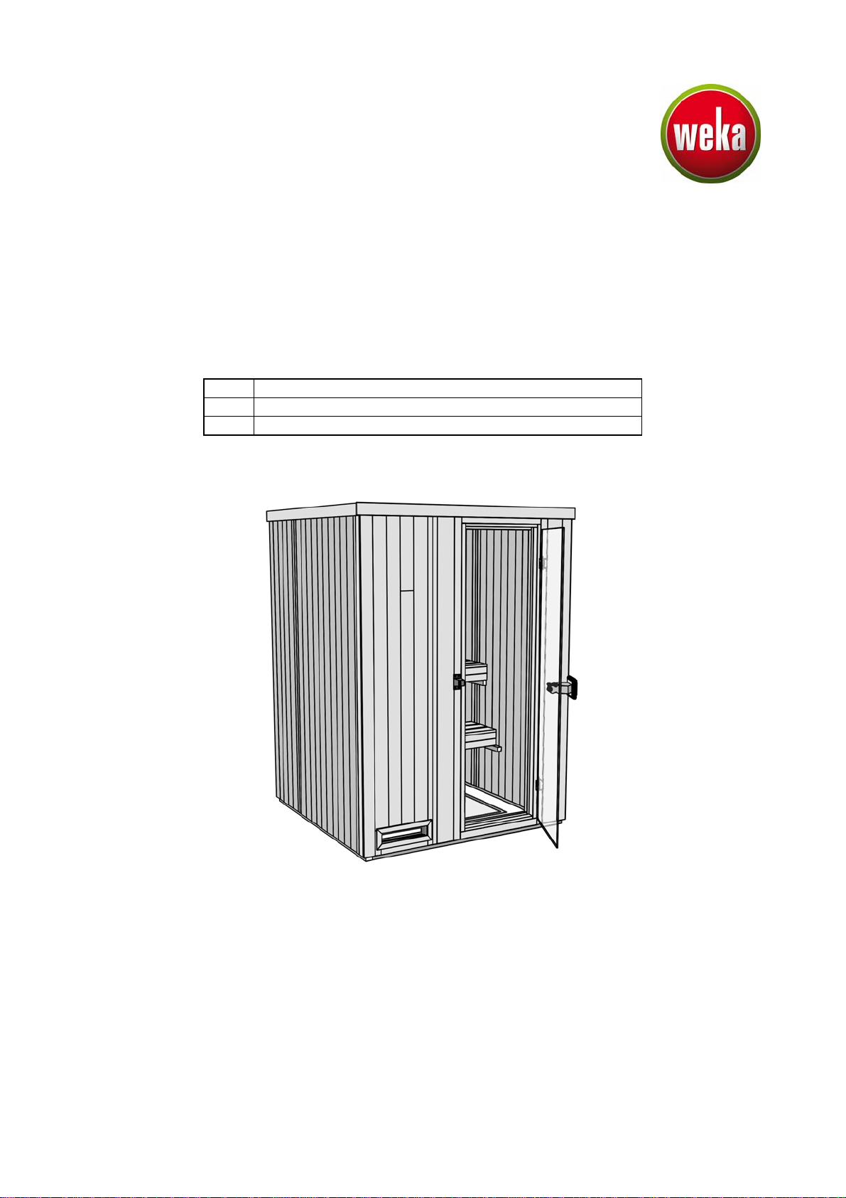
Die Sauna kann spiegelverkehrt aufgebaut werden.
Um dem Absenken der Glastür vorzubeugen, ziehen Sie die Inbusschraube der Beschläge fest an.
Die Türbeschläge sind nach mehrmaliger Nutzung der Kabine zu überprüfen und gegebenenfalls
nachzujustieren. Die Schrauben zur Befestigung der Türbeschläge und Türgriffe sind ebenfalls nach
mehrmaliger Nutzung der Kabine nachzuziehen.
Sollten die Holzfaserplatten der Rückwand- und Deckenelemente Unebenheiten oder geringe wellenförmige
Verformungen aufweisen, so hat dies keinen negativen Einfluss auf die Nutzung, die Optik oder den
Wärmehaushalt der Kabine und sind daher kein Reklamationsgrund.
Garantiebestimmungen der weka Holzbau GmbH
Wir gewähren Ihnen zu nachfolgenden Konditionen – jedoch nur auf die Holzteile unserer Produkte (weka-
Produkt genannt), nicht auf damit verbundene Bauteile oder Bestandteile des weka-Produkts aus anderem
Material als Holz – ab Lieferdatum 5 Jahre Garantie auf Funktion. Innerhalb der Garantiezeit werden
fehlerhafte Teile oder fehlende Teile der Ware oder die Ware selbst nach unserer Wahl ersetzt. Vom
Garantieumfang erfasst ist lediglich der kostenlose Ersatz des jeweils mangelhaften oder defekten Holzteils.
Nicht im Garantieumfang enthalten sind Folge- oder Zusatzkosten, insbesondere keine Liefer- und Auf- oder
Umbaukosten.
Die Garantie ist ausgeschlossen, wenn:
- von der jeweiligen Montageanleitung abgewichen wurde,
- Veränderungen (zusätzliche An- oder Umbauten) an dem Produkt im Vergleich zur
Montageanleitung vorgenommen wurden,
- die jeweils angegebenen Belastungsgrenzen (z.B. Schneelast usw.) überschritten wurden,
- das weka-Produkt falsch gegründet (Fundament / Bodenplatte o.ä.) wurde, insbesondere bei
Verstößen gegen die Regeln der Baukunst,
- unterlassene oder nicht ausreichende Pflege (Wartung: Holzschutz, Holzanstrich usw.) des Holzes
vorgenommen wurde.
- Windgeschwindigkeiten über Stärke 7, Naturkatastrophen oder gewaltsame Einwirkungen den
Schaden am weka-Produkt verursacht haben.
- der Mangel in holztypischen Farbveränderungen, Rissbildungen, Verwerfungen, Schwinden, Quellen
oder ähnlichen normalen, in der Natur des Werkstoffes „Holz“ begründeten Veränderungen besteht.
Garantieansprüche können nur in Verbindung mit Originalpackzettel und Originalkaufbeleg in Anspruch
genommen werden und müssen innerhalb der Garantiezeit schriftlich, per Telefax oder per e-Mail geltend
gemacht werden. Anspruchsvoraussetzung ist eine unverzügliche Anzeige des Mangels bzw. des Schadens
in Form einer geordneten Darstellung des Schadens in Bild und Text.
Garantieansprüche sind zu richten an:
weka Holzbau GmbH, Johannesstraße 16, 17034 Neubrandenburg
Fax: 0395/42908-83; e-Mail: info@weka-holzbau.com
Montagebedingungen für weka - Montageteam
Wenn Sie Montagehilfe in Anspruch nehmen und dazu ein weka - Montageteam rufen, wird die weka
Holzbau GmbH für Sie wie folgt tätig:
Montage bedeutet das anleitungsgemäße Zusammenfügen (Aufbau) der gelieferten Einzelteile der Ware
ohne Anstrich, Lieferung und Montage von Zubehör und Zubehörteilen. Elektrische Anschlüsse sind in den
Montageleistungen nicht enthalten
Die aufzubauende Ware muss sich am Aufbauort/Standort/Standfläche befinden. Transport des Artikels oder
der Einzelteile über eine Entfernung von 5m hinaus oder in ein anderes Geschoss sind im angebotenen
Montagepreis nicht enthalten. Der Untergrund muss tragfähig, horizontal und eben sein.
Im Zweifel gilt für die Ebenheit: DIN 18202 „Ebenheitstoleranzen im Hochbau“, Tab.3, Zeile 3, mit einer
maximalen Höhendifferenz der am weitesten von einander entfernten Punkten von ca. 10 bis 11mm.
Alle vorbereitenden Arbeiten müssen gemäß den technischen Regeln vor Beginn der Montage ausgeführt
sein. Die von Ihnen gefertigten oder gewählten Untergründe/Fußböden/ Fundamente müssen für die
Montage geeignet sein.
Technische Änderungen vorbehalten! 4© Copyright HRB 3662
Werkzeug
Folgendes Werkzeug sollten Sie vor Beginn der Montage zurecht gelegt haben.
Wasserwaage Rollmaß Bohrmaschine Elektroschrauber Hammer Schraubendreher
Feinsäge / Handkreissäge Universalmesser Schraubenschlüssel Inbusschlüssel
Abkürzungen / Symbole:
Abb. Abbildung
cm - Zentimeter
mm - Millimeter
ca. - circa
- Zuluftöffnung
- Abluftöffnung
Aufbauvarianten
Nicht im Lieferumfang enthalten!
Technische Änderungen vorbehalten! 5© Copyright HRB 3662
- en -
Dear customer
Thank you very much for choosing a weka product.
Read these instructions through completely before assembling your product in order to avoid errors in
assembly or damage.
IMPORTANT
Please use the enclosed packing list to check immediately that your weka product has been
delivered complete and intact.
Please do not dispose of the packing list before the guarantee period has expired. This list enables you to
check that all the individual parts are present. It should be retained along with the proof of purchase. Any
complaints which may arise can probably be easily rectified with this list. The item numbers on the packing
list do not correspond to the item numbers in the following assembly instructions.
We recommend that 2 people carry out the assembly.
In order to prevent accidents, we recommend that children are kept out of the direct vicinity during assembly.
We reserve the right to make further technological developments. This means that there many be minor
deviations in the illustrations.
Please do not simply throw away the packaging material. Paper, card and corrugated board as well as
plastic packaging materials should be placed in the correct collection containers.
Wood
Healthy knots, light discoloration and small cracks are characteristic of the wood, lending the cabin its natural
appearance. They are therefore not grounds for complaint.
Prior to assembly
A minimum room height of 205 cm is required to set up the cabin.
The wall clearance should be at least 10 cm.
The floor must be level and horizontal, as otherwise it may cause functional interference.
The best location for your cabin would be a dry, well ventilated room.
A stone or tiled floor is both a practical and an attractive floor covering.
If there is a different floor covering, a slab with minimum dimensions of 40 x 50 cm must be placed below the
stove to prevent damage to the floor.
Safety tips
Please note that children should not be permitted unsupervised in the cabin.
Do not place any objects on the sauna furnace – THERE IS A FIRE RISK!
Before the heating phase begins, ensure that no flammable objects are located in the vicinity of the furnace.
Only use the sauna infusion concentrate in diluted form. Information on correct usage can be found on the
containers.
Do not use any chemical adhesives inside the sauna. Only wood glue may be used.
After using the sauna, leave the door open to allow it to cool down. Ensure that the room in which the sauna
is located is well ventilated.
The information plate is to fixed in a clearly
visible position near the sauna furnace.
Care instructions
In order to ensure that you are able to benefit from the sauna for a long time to come, clean it regularly.
The unsurpassed mild and beneficial climate in the sauna is achieved as a result of the natural diffusion and
storage ability of the solid wood.
For this reason, the surface of the wooden sections must not be treated in any way.
If the sauna is not used for some time, we recommend that it is heated up for at least half an hour, once a
week. This will prevent any unwanted buildup of moisture.
A small amount of resin discharge from the wood surface is unavoidable. The dry resin residue can be
removed with fine sandpaper.
Installation of the electrics
The electrics may only be installed by a qualified electrician in accordance with the VDE and EVU guidelines.
Information on assembly of the sauna furnace and the control device can be found in the enclosed assembly
instructions.
Technische Änderungen vorbehalten! 6© Copyright HRB 3662
Assembly recommendations
Please drill pilot holes for all screw connections to avoid
damaging the wood. The following symbol in the
instructions will indicate when this is necessary:
General assembly of the wall elements
Figure shows a cross-section through a wall
section with profile wood boarding on both sides.
All wall elements are equipped with a vapour
barrier and heat insulation. After assembly of
the sauna, the vapour barrier must always be
located directly behind the interior boarding.
The inner side of the wall element is
indicated on the wooden frame by the
following stamp
innen .
inside-= innen
Before erecting the individual elements, take
care to ensure that the groove side
(viewed from outside) is always on the left.
Mounting timber has been incorporated into the
wall elements for the bench mountings.
These are located approx. 36 cm and 80 cm above
the floor. The location of this timber can be seen
at the visible screw heads in the element frames.
Each time you install a wall element, ensure that
these screw heads are located in the lower half of
the element.
Preparing the wall panel for installation of the multi-function control system
For installation of the control unit,
the opening height in the wall panel
must be 10 cm.
To attain this height, push the loose
sheathing board and the plastic pipes
upward and out and shorten the
board and pipes accordingly.
NOTE: It is absolutely necessary
that this be carried out
BEFORE the wall panel is set up.
R1-R5: These serve as assembly tubing
for the mains connection electric cable,
the sauna lamp and the sauna furnace
ending at the control unit.
R1 + R4: for running cable from oven
control system module to the
sauna oven
R2: for running cable from oven
control system modul to the
control unit
R3 + R5: reserve
Technische Änderungen vorbehalten! 7© Copyright HRB 3662
The sauna can also be built in its mirror image.
To prevent the dropping of the glass door, tighten the allen screw of the braces firmly.
The door fittings are to be checked when the cabin has been used repeatedly and adjusted if required.
The screws for fastening the door fittings and door handles are also to be tightened after the cabin has been
used repeatedly. Should the wood fibreboard of the rear wall and ceiling element panels show any
unevenness or slight undulating deformities, these have no negative influence on the use, appearance or the
thermal efficiency of the cabin and are therefore not grounds for complaint.
Warranty terms of weka Holzbau GmbH
We guarantee the function of our products for 5 years from the date of delivery based on the following
conditions – however only on the wooden parts of our products (hereinafter weka product) and not on
connected components or parts of the weka product made of another material besides wood. Within the
warranty period defective parts or missing parts of the product or the product itself will be replaced at our
discretion. The warranty extends only to the free-of-charge replacement of the respective faulty or defective
wooden part. The warranty does not cover any consequential or additional costs, in particular no delivery
and installation or modification costs.
The warranty is void in case of:
- failure to follow the assembly instructions,
- changes (additions or modifications) made to the product diverging from the assembly instructions,
- load limits (e.g. snow load, etc.) having been exceeded,
- the weka product having been installed on an incorrect foundation or floor plate, etc., in particular in
case of violation of the rules of architecture,
- lack of or insufficient care of the wood (maintenance measures such as preservation or painting of
the wood),
- wind speeds stronger than force 7 (moderate gales), natural catastrophes or brute force having
caused the damage to the weka product,
- the deficiency consisting in changes which are typical for wood, such as discoloration, formation of
cracks, warping, shrinking, swelling or similar normal effects on the material "wood".
Warranty claims must be accompanied by the original packing slip and the original sales receipt and must be
submitted within the warranty period in writing or by fax or e-mail. A further prerequisite for a claim is the
immediate notification of the defect or damage in the form of pictures and a written description of the defect.
Address all warranty claims to:
weka Holzbau GmbH, Johannesstraße 16, 17034 Neubrandenburg
Fax: 0395/42908-83; E-mail: info@weka-holzbau.com
Assembly conditions for a weka assembly team
If you wish for help assembling your cabin and choose to employ a weka assembly team, weka Holzbau
GmbH will carry out the following services for you:
Assembly means putting together (installation) of the individual parts supplied. It does not include treating
them with a wood protection agent, the delivery and assembly of accessories and accessory parts. Electrical
connections are not included in the assembly service.
The items to be assembled must be located at the installation site/location/base area. Transport of the article
or the individual parts over a distance greater than 5 m or to another level is not included in the assembly
price quoted. The substrate must be stable, horizontal and level.
In the event of doubt, reference should be made to DIN 18202 ‘Level tolerances in building construction’,
tab. 3, row 3, with a maximum height difference at the furthest points of approx. 10 to 11 mm.
All preparatory work must have been carried out in accordance with the technical regulations before
assembly begins. The substrates/floors/foundations constructed or selected by you must be suitable for the
assembly.
Technische Änderungen vorbehalten! 8© Copyright HRB 3662
Tools
You should have the following tools to hand before beginning assembly.
Spring tape Elektric
Spirit level measure Drill screwdriver Hammer Screwdriver
Mitre saw/
hand disk saw Universal cutter Spanner Allen key
Abbreviations / Symbols
Abb. Figure
cm - Centimetre
mm - Millimetre
ca. - approximately/approx.
- Supply air
- Outgoing air
Design variant
Not included in delivery!
Technische Änderungen vorbehalten! 9© Copyright HRB 3662
- fr -
Chère Cliente, cher Client
Nous vous remercions d'avoir choisi un produit weka.
Lisez entièrement la présente notice avant de procéder à l'assemblage afin d'éviter les erreurs et les
dommages.
IMPORTANT !
Veuillez vérifier immédiatement, à l'aide de la liste des pièces, si le produit weka est
arrivé complet et en bon état.
Ne détruisez la liste des pièces qu'une fois la garantie écoulée. Cette liste vous permet de vérifier si les
pièces détachées sont complètes et doit être conservée avec le justificatif d'achat. Elle vous permettra de
faire valoir aisément d'éventuelles réclamations. Les numéros de pos. de la liste des pièces ne sont pas
identiques aux numéros de pos. de la présente notice de montage.
Nous vous recommandons d'effectuer le montage à 2 personnes.
Afin de prévenir tout accident, éviter la présence d'enfants à proximité durant le montage.
Nous nous réservons le droit d'apporter aux produits des modifications dans le cadre de l'évolution
technique.
De légères différences sont par conséquent possibles par rapport aux illustrations.
Ne pas jeter simplement le matériel d'emballage! Les emballages en papier, carton et carton ondulé doivent
être déposés dans le container de tri correspondant.
Le bois
Les noeuds robustes, les légères décolorations et les petites fissures sont typiques du bois, confèrent aux
cabines leur aspect naturel et ne constituent pas un motif de réclamation.
Avant le montage
L'installation de la cabine nécessite une hauteur sous plafond minimale de 205 cm. La distance aux murs
doit être d'au moins 10 cm.
Le sol doit être plan et horizontal sous peine de risques de dysfonctionnement.
La cabine sera utilisée au mieux dans un local sec et bien aéré.
Les sols en pierre ou en carrelage sont tout à la fois pratiques et esthétiques.
Si le revêtement de sol est différent, une dalle de dimension minimale 40 x 50 cm doit être posée sous le
poêle pour éviter d'endommager le sol.
Conseils de sécurité
Veillez à ce que les enfants ne restent pas dans la cabine sans surveillance !
Ne déposez pas d'objets sur le four du sauna. - DANGER D'INCENDIE !
Assurez-vous, dès le début de la phase de chauffe, qu'aucun objet inflammable ne se trouve à proximité du
four.
N'utilisez les concentrés pour sauna que sous forme diluée. Les informations nécessaires pour leur bonne
utilisation figurent sur les récipients.
N'utilisez pas de colles chimiques à l'intérieur du sauna mais tout au plus de la colle à bois.
Après l'utilisation, laissez le sauna refroidir avec la porte ouverte. La pièce dans laquelle se trouve le sauna
doit toujours être bien aérée.
La plaque d'information doit être fixée à un endroit
bien visible à proximité du four du sauna.
Entretien
Le coffrage de paroi ne doit pas être masqué à l'intérieur ou entrer en contact avec l'humidité.
Après utilisation, laissez refroidir la cabine avec la porte ouverte.
Assurez toujours une bonne ventilation de la pièce dans laquelle se trouve la cabine.
En cas de non utilisation prolongée, nous recommandons de garder la porte de la cabine ouverte.
Les incrustations tenaces de saletés sur le bois peuvent être éliminées avec un papier abrasif.
Installation électrique
Pour l'installation électrique la norme NF C 15 -100 est à respecter.
L'installation électrique doit être effectuée uniquement par un électricien agréé, en respect des normes de
l'union des électriciens allemands VDE et de l'entreprise de fourniture d'électricité. Pour les informations
relatives au montage du four du sauna et de l'unité de commande, veuillez vous référer aux notices de
montage correspondantes.