Welbilt KOLPAK Programming manual

Protecting Your Future
Refrigeration System
Original Instructions
Installation, Operation and Maintenance Manual
This manual is updated as new information and models are released. Visit our website for the latest manual.
Part Number: 550001058-14 8/21

2
Read this manual thoroughly before operating, installing or
performing maintenance on the equipment. Failure to follow
instructions in this manual can cause property damage, injury
or death.
Ensure that all field wiring conforms to the equipment
requirements and all applicable local and national codes.
Installation and maintenance/servicing are to be performed
only by trained and qualified personnel familiar with
commercial refrigeration systems.
Indicates a situation that, if not avoided, could damage the
refrigeration system or result in minor injury.
Safety Notices
NOTE: Indicates useful, extra information about the
procedure you are performing.
DANGER
Indicates a hazardous situation that, if not avoided, will
result in death or serious injury. This applies to the most
extreme situations.
Notice
Indicates information considered important, but not hazard-
related (e.g. messages relating to property damage).
Disconnect all power sources before servicing the refrigeration
equipment.
Use appropriate eye protection during installation and servicing.
Sheet metal and coil surfaces have sharp edges. Use appropriate
protective gloves to prevent injury.
Indicates a hazardous situation that, if not avoided, could result
in death or serious injury.

3
Table of Contents
Section 1
General Information
Receiving Inspection ........................................................ .......................................................... 4
Warranty Information................................................................................................................. 4
Section 2
Installation
Condensing Units ........................................................................................................................ 5
Evaporator Units ......................................................................................................................... 6
Section 3
Wiring
Wiring ......................................................................................................................................... 8
Section 4
Piping
Piping .......................................................................................................................................... 9
Cleanliness .......................................................................................................................... 9
Pipe Supports...................................................................................................................... 9
Oil Traps ............................................................................................................................ 10
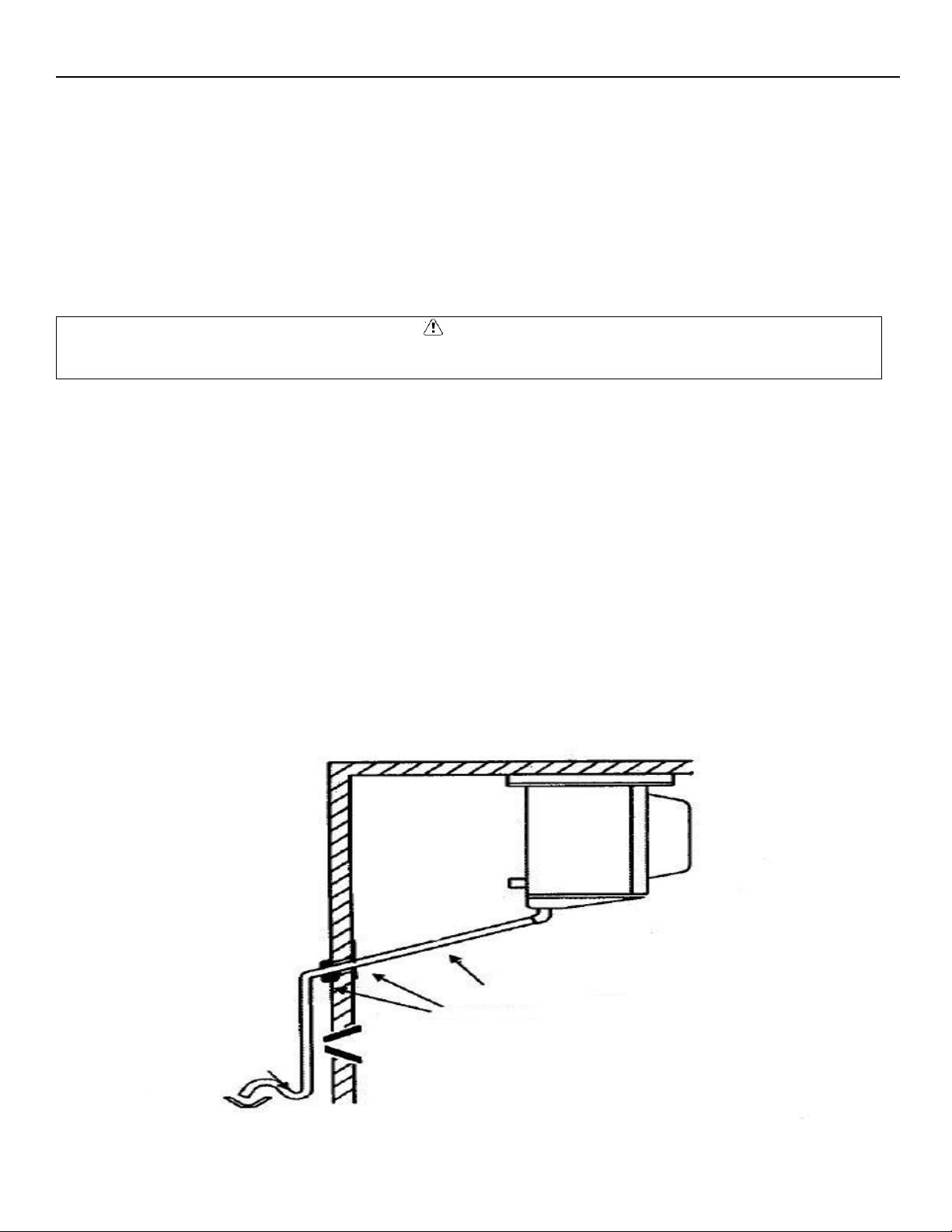
Drain Lines ........................................................................................................................ 10
Pre-Charged Lines ............................................................................................................. 11
Leak Testing .............................................................................................................................. 12
PR Models ......................................................................................................................... 12
PC Models ......................................................................................................................... 13
PCL Models ....................................................................................................................... 13
System Evacuation .................................................................................................................... 13
PR Models ......................................................................................................................... 13
PC Models ......................................................................................................................... 13
PCL Models ....................................................................................................................... 14
Refrigerant Charging ................................................................................................................. 14
Section 5
Operational Start-Up
Pre-Start Checks........................................................................................................................ 15
Compressor Mounts.................................................................................................................. 15
Start-Up .................................................................................................................................... 16
Compressor Superheat.............................................................................................................. 16
Evaporator Superheat ............................................................................................................... 17
Johnson Control Thermostat..................................................................................................... 18
Three button Touch Pad ................................................................................................... 18
Parameter Codes And Modes of Operation...................................................................... 19
Basic Menu........................................................................................................................ 23
Advanced Menu................................................................................................................ 24
Setting Up A Regular Or Timed Defrost Off-Cycle............................................................. 26
Troubleshooting................................................................................................................ 29
Electric Defrost Timer................................................................................................................ 31
Section 6
Maintenance
Preventive Maintenance Tasks.................................................................................................. 33
P.O.E. Lubricants ....................................................................................................................... 33
Section 7
Troubleshooting
Evaporator ................................................................................................................................ 34
Condensing Unit........................................................................................................................ 35
System Start-Up Checklist........................................................................................................................... 37

4
Section 1
General Information
Receiving Inspection
1. Check the shipment carefully and compare to the bill of lading.
2. Account for all items listed and inspect each container for damage.
3. Carefully inspect for any concealed damage.
4. Report any shortages or damages to the carrier, noteon the bill of lading, and file a freight claim.
5. Damaged material cannot be returned tothe manufacturer without prior approval.
6. A Return Material Authorization (RMA) must be obtained. Contact a sales representative at 800-826- 7036.
Warranty Information
For information regarding warranty guidelines, claim form, product registration, warranty verification, or
locating a service provider please visit our website at www.kolpak.com or call 800-225-9916.

5
Section 2
Installation
Condensing Units
•Check the selected installation location to ensure that racks, braces, flooring, foundations, etc. are adequate to
support the condensing unit weight.
•The installation location is clean, dry, and level.
•Locate away from corrosive and noise sensitive atmospheres.
•Use the condensing unit skid and base when moving the unit. Do not remove unit from skid until the unit is moved to
the mounting location.
•Mount the condensing unit base to pads or structural rails using properly sized bolts through the unit base. Center of
condensing unit needs to be properly supported.
•Locate where there is a sufficient and unrestricted supply of clean ambient air.
•Locate where this is adequate space for the removal of the heated discharged air from the condensing unit area.
•Do not position multiple units so that discharge air from one unit is blowing into the condenser inlet air of the other
unit.
•All sides of the unit should be positioned a minimum distance equal to the total width of the condensing unit away
from any other unit, wall, or obstruction.
•Check the selected installation location to ensure that racks, braces, flooring, foundations, etc. are adequate to
support the condensing unit weight.
•The installation location is clean, dry, and level.
•Locate away from corrosive and noise sensitive atmospheres.
•Use the condensing unit skid and base when moving the unit. Do not remove unit from skid until the unit is moved to
the mounting location.
•Mount the condensing unit base to pads or structural rails using properly sized bolts through the unit base. Center of
condensing unit needs to be properly supported.

6
Example of Multiple Units with Horizontal Airflow
Evaporator Units
•Do not place the evaporator above or close to door openings. This will help prevent potential icing problems.
•Allow a minimum clearance equal to or greater than the coil height on all sides of the coil for proper air flow and
service access.
•Use the evaporator coil for a template to locate and drill the mounting holes (1/2” diameter).
•Place a 1” and a 1-5/8” washer on each nylon bolt and insert through the drilled mounting holes in the ceiling from
the exterior of the walk-in ceiling panel.
NOTE: Nylon bolts are supplied to prevent thermal transfer between the exterior of the walk-in and the interior of the walk-
in. Do not use metal bolts.
•Lift the evaporator coil until the nylon bolts extend through the mounting brackets.
•Install washers and secure with nuts. Tighten until the coil is firm against the ceiling. The evaporator coil must be
level.
•Additional information is available in the installation manual supplied with the evaporator.
CAUTION
Failure to observe clearance and air flow requirements will result in poor system performance and premature equipment
failure!
CAUTION
Failure to observe clearance and air flow requirements will result in poor system performance and premature equipment
failure!
BUILDING WALL
(VIEWED FROM ABOVE)
MINIMUM
DISTANCE
24”
INTAKE AIR
MINIMUM DISTANCE 24”
24”
INTAKE AIR
MINIMUM DISTANCE 24”
24”
AIR
FLOW
AIR
FLOW

7
Evaporator Coil Mounting Diagram

8
Section 3
Wiring
Wiring
•All electrical connections and routing must comply with local and national codes.
•Do not modify the factory installed wiring without written factory approval.
•The field wiring must enter through the knockouts provided.
•Refer to the nameplate on the condensing or evaporator coil to determine the proper electrical power supply.
•Wire type should be of copper conductor only and properly sized to handle the electrical load.
•The unit and coil must be properly grounded.
•Condensing unit wiring diagrams are and attached inside the electrical box cover.
•Evaporator coil wiring diagrams are and inside the evaporator cover.
•To view Basic Cooler/Freezer Evaporator Wiring Service Video, scan the QR code below.
•For the latest wiring diagrams, scan the QR code below.
WARNING
All wiring must comply with local and national codes. Wiring must be performed only by a refrigeration technician or
certified electrician. Failure to follow these guidelines may result in injury!
CAUTION
Check all wiring connections, including factory terminals, before operation. Connections can become loose during shipment
and installation.

9
Section 4
Piping
Piping
•All refrigeration piping and components are to be installed in accordance with applicable local and national codes and
in conformance with industry refrigeration guidelines to ensure proper operation of the refrigeration system.
•Only refrigeration grade copper tubing should be used.
•Long radius elbows should be used. Short radius elbows have points of excessive stress concentration and are subject
to breaking at these points, do not use short radius elbows.
•Suction lines must be insulated with a minimum ¾” thick insulation tubing to reduce heat pick-up.
Cleanliness
•Condensing units and evaporator coils are cleaned and dehydrated at the factory.
•The condensing unit must remain closed and pressurized until the piping is complete and final connections are ready
to be made.
CAUTION
The maximum air exposure for dehydrated condensing units is 15 minutes. Systems exposed longer than 15 minutes must
have the compressor oil and drier filter replaced. Leaving a system exposed to the atmosphere for more than 15 minutes can
result in premature system failure.
•Do not remove base mount valve covers until work is ready to be performed.
•Ensure that all refrigeration tubing is clean and dry prior to installation.
•Use only tubing cutters when trimming tubing to the proper length. Do not use saws to cut tubing.
CAUTION
The use of saws to cut tubing can contaminate the system with copper chips causing premature system failure.
•Brazing joints require a dry inert gas, typically nitrogen, be passed through the lines at a low pressure to prevent
scaling and oxidation.
•Use only silver solder brazing alloys. Minimize the amount of flux to prevent internal contamination. Flux only the
male portion of the joint.
•Thoroughly clean fluxed joints after brazing.
CAUTION
Dry inert gas must be passed through the system while brazing to prevent scaling and oxidation. Scaling and oxides can clog
refrigeration components resulting in system failure.
Pipe Supports
•All tubing should be supported in a least two locations (near the end of each tubing run).
•Long runs will require additional support.
•As a guide, support 3/8” to 7/8” pipe every five feet, 1-1/8” to 1-3/8” every seven feet, and 1-5/8” to 2-1/8” every ten
feet.
•Do not leave a corner unsupported when changing directions.
•Place supports within 2 feet of each direction change.
•Piping that is attached to a vibrating object (such as a compressor or compressor base) must be supported in a
manner that will not restrict the movement of the vibrating object.
•Rigid mounting will fatigue the tubing causing refrigerant leaks.

10
Oil Traps
•To ensure proper oil return to the compressor, a P-type oil trap should be installed at the base of each suction riser of
four feet or more.
•The suction trap must be the same size as the suction line.
•Additional traps are necessary for long vertical risers. Add a trap for each length of pipe (approximately 20 feet) to
insure proper oil return.
•Suction lines must slope ¼” per 10 feet toward the compressor.
•Install a suction line trap at the evaporator outlet if the suction line rises to a point higher than the connection on the
evaporator.
CAUTION
Failure to properly install oil traps can prevent sufficient oil return to the compressor resulting in premature compressor
failure.
Drain Lines
•Evaporator coil drain lines should be pitched a minimum of 1/2” per foot to allow proper drainage and exit the walk-in
as quickly as possible.
•Insulate and seal the drain line where it passes through the wall.
•Copper drain line is required.
•Freezer compartment drain lines must have heat tape wrapped around the copper drain line and must have ¾” thick
insulation tubing.
•Do not locate drain line P-traps within the freezer space.
•Do not reduce the drain line size.
•Locate a drain line P-trap outside of the cooler space.
•Any outdoor P-traps exposed to low ambient temperatures should be wrapped with a drain line heater (provide 20
watts of heat per foot of drain line at 0°F, 30 watts per foot at -20°F.
•Freezer/cooler combo boxes can have one common drain line. However, there must be a P-trap located between the
freezer evaporator and the cooler evaporator located inside the cooler compartment.
•The cooler compartment P-trap should be located between the cooler evaporator and the external drain location.

11
Pre-Charged lines and Quick Connects
•Route the suction and liquid line sets between the condensing unit and evaporator coil following the piping guidelines
identified in this manual.
•Remove the dust caps from the quick connect fittings and verify that the o-rings are intact.
•Wipe the coupling seals and threaded surfaces with a clean cloth to prevent contamination.
•Lubricate the threads and o-rings with Polyol Ester oil.
•Thread the coupling halves together by hand to ensure proper thread mating.
•Tighten with a wrench until the coupling bodies “bottom” or until there is definite resistance.
•Tighten an additional ¼ turn to ensure proper brass-to-brass seating.
•Once the system is opened and pressurized, check each fitting for refrigerant leaks. If a leak is detected, tighten until
the leak stops.
WARNING
Do not loosen and disconnect the quick connect fittings before reclaiming the refrigerant and depressurizing the system.
Disconnecting a pressurized system can result in injury!

12
CAUTION
Quick connects are for one time use only. Once disconnected, the coupling cannot be re-used. Refrigerant leaks will occur if
the couplings are re-used resulting in poor system performance.
•Excess line set length should never be allowed to coil in the vertical position. Excess line length should be laid flat on
its side.
Leak Testing
•After all connections are complete the refrigeration system must be tested for leaks.
•Failure to perform a leak test can result in unsatisfactory system performance, additional servicing and service costs,
and possible system failure.
•Leak test should be performed using an electronic leak detector.
•All joints and components, both factory and field installed, should be thoroughly inspected for leaks.
•The system installation must be leak free!
Leak Testing “PR” model systems
•Open both the liquid and suction service valves.
•Ensure the solenoid valve is energized and open.
•Add 50 psi refrigerant, then pressurize with dry nitrogen to the low side test pressure identified on the unit rating
label.
•Allow thirty minutes for refrigerant to reach all parts of the system.
•Check all joints and components with an electronic leak detector.

13
Leak Testing “PC” model systems
•Leave the service valves closed, the condensing unit is charged with refrigerant.
•Ensure the solenoid valve is energized and open.
•Add 50 psi refrigerant, then pressurize with dry nitrogen to the low side test pressure identified on the unit rating
label.
•Allow thirty minutes for refrigerant to reach all parts of the system.
•Check all joints and components with an electronic leak detector.
Leak Testing “PCL” model systems
•Open both the liquid and suction service valves.
•Ensure the solenoid valve is energized and open.
•Allow thirty minutes for refrigerant to reach all parts of the system.
•Check all joints and components with an electronic leak detector.
•If a leak is detected, relieve the pressure and/or reclaim the refrigerant and repair the leak.
•If additional brazing is required, pass a dry inert gas (nitrogen) through the system to prevent contamination.
•Reference page 12 of this manual for leaks located at quick connects couplings.
•Retest the system as outlined above until no leaks are detected.
CAUTION
If a braze joint is detected leaking, dry inert gas must be passed through the system while repairing the joint to prevent
scaling and oxidation. Scaling and oxides can clog refrigeration components resulting in system failure.
CAUTION
Always use the system specified refrigerant when pressuring to perform a leak test.
System Evacuation
•Evacuation of the refrigeration system is necessary to remove all air and moisture from the system.
•A reliable rotary vacuum pump with an accurate deep vacuum gauge is recommended.
•Do not use the system compressor as a vacuum pump and do not operate the compressor while the system is under
vacuum.
Evacuation of “PR” model systems
•Open both the liquid and suction service valves.
•Ensure the solenoid valve is energized and open.
•Connect vacuum pump to the liquid and suction service valves located on the condensing unit.
•Evacuate the system to 250 microns and maintain for a minimum of 4 hours.
•Perform a vacuum decay test for a minimum of ten minutes to ensure the system is leak free and dry.
Evacuation of “PC” model systems
•Leave the service valves closed, the condensing unit has been evacuated and is charged with refrigerant.
•Ensure the solenoid valve is energized and open.
•Connect vacuum pump to the liquid and suction service valves. located on the condensing unit.
•Evacuate the system to 250 microns and maintain for a minimum of 4 hours.
•Perform a vacuum decay test for a minimum of ten minutes to ensure the system is leak free and dry.

14
Evacuation of “PCL” model systems
•“PCL” systems do not require evacuation.
CAUTION
Do not use the system compressor to evacuate the system. Do not start the compressor while the system is under vacuum.
This may damage to the compressor and cause premature system failure.
Refrigerant Charging
•The refrigerant charge should be added to the system through the liquid line service valve located on the condensing
unit.
•Do not charge liquid refrigerant into the suction service valve!
•The initial charge should be determined by weight and sight glass indication.
•Start the system. If the condensing temperature is 105° F or greater, charge the system until the sight glass clears.
•If the condensing unit temperature is below 105° F, reduce the condenser face surface area to raise the discharge
pressures above 105° F and to charge to a clear sight glass.
•Return to a full condenser face area when charging is complete.
NOTE: PC & PCL refrigerant charge amounts are based on average ambient operating temperatures across the United
States. Any refrigerant amount added or removed based on ambient operating temperatures is considered part of normal
maintenance and is not covered under warranty.
CAUTION
Do not charge liquid refrigerant into the suction service valve located on the condensing unit. Do not overcharge the system.
These conditions can permit liquid refrigerant to enter the compressor and cause damage to internal components resulting
in premature system failure.

15
Section 5
Operational Start-Up
Pre-Start Checks
•The first 2 – 4 hours of operation after initial start-up is a critical time.
•Do not just start the system and leave.
•Pressure values, compressor and evaporator superheat, and inspecting for excessive vibrations and loose connections
are some of checks that must be performed prior to leaving the system.
•Verify that all service valves are fully open.
•Ensure that all refrigerant and electrical connections are tight.
•Verify that the wiring and piping is properly routed and secured.
•The compressor mounting bolts are properly adjusted (see compressor mounts on page 18).
•All fan motors and mounting brackets are tight.
•The condensing unit base and evaporator coil are properly secured.
Compressor Mounts
•Hermetic Compressors – hermetic compressor springs are mounted internally; check the compressor mounting bolts
to ensure the nuts have not become loose during shipment.
•Semi-Hermetic Compressors – most semi-hermetic compressors have external spring mounts and are factory
assembled. The following actions are required once the condensing unit is installed and before system start-up:
oLoosen the upper mounting nuts.
oRemove the spring steel clips from the mounting springs.
oRetighten the upper mounting nuts until the compressor can float on the springs approximately 1/16”
between the mounting nut and rubber grommet.
CAUTION
Failure to ensure the compressor mounts are properly tightened can result in fatigue to the system piping causing leaks and
poor system performance.
Compressor
Mounting Foot
Mounting Nut
(Upper)
Mounting
Stud
Rubber
Spacer
Mounting
Spring
Mounting
Base
Locking
Device
Mounting Nut
(Lower)
Properly Adjusted Compressor

16
Start-Up
CAUTION
Do not start the system while in a vacuum. Do not leave the system unattended until normal operating conditions are
achieved.
•Operate the system for a minimum of two hours and perform checks of the following:
oCheck the compressor discharge and suction pressures to ensure they are in the normal operating range.
oCheck the liquid line sight glass for proper refrigerant charge (based off of 105ºF condenser coil).
•Monitor the compressor oil level (semi-hermetic compressors), add oil as necessary to keep the level at ¾ sight glass
when idle and ½ sight glass when running.
•Check the voltage and amperage at the compressor terminals. Voltage must be within +10% or -5% of the rating
indicted on the condensing unit name plate. On three phase compressors, verify there is a balanced load.
•Check all fans on the evaporator coil and condensing unit to be sure they are operational and turning in the correct
direction.
•Check the piping and electrical connections for vibration. Add supports and strapping if needed.
•Check the crankcase heater operation (if equipped).
•Set the defrost control time and verify the defrost initiation settings. See pages 28-30 for additional details.
•Set temperature control to desired temperature range.
•Check the compressor and evaporator superheat (reference pages 21-23).
•After all system checks have been checked, properly adjusted, and verified, replace all Schrader caps, service valve
caps, electrical box covers, housings, etc. File a copy of this manual for future reference.
CAUTION
Failure to check and properly adjust compressor superheat can result in premature system failure.
Compressor Superheat
•Compressor superheat is a critical value that must be checked. Check the compressor superheat as follows:
oDetermine the suction pressure at the suction service valve of the compressor.
oDetermine the saturation temperature at the observed suction pressure using refrigeration pressure
temperature tables.
oMeasure the suction line temperature 6 -10 inches away from the compressor.
oSubtract the saturation temperature (step 2) from the measured temperature (step 3). The difference is the
superheat of suction gas.
•A low suction superheat can cause liquid to return to the compressor. This will cause dilution of the oil and eventual
failure of the bearings, rings and valves.
•A high suction superheat will cause excessive discharge temperatures, which cause a breakdown of the oil. This
causes piston ring wear, and piston and cylinder wall damage.
•System capacity decreases as the suction superheat increases.
•For maximum system capacity, keep the suction superheat as low as practical. Copeland requires a minimum
compressor superheat of 20°F; however, to improve compressor life, 25°F to 40°F is preferred.
•Adjust the expansion valve at the evaporator when adjustments to the suction superheat are necessary.
•Refer to “Evaporator Superheat” on the next 2 pages for more information.

17
Evaporator Superheat
•Check the evaporator superheat once the walk-in has reached the desired temperature. Generally, systems with a
design temperature drop of 10°F should have an evaporator superheat value of 6°-10°F on freezers and 8°-12°F on
coolers for maximum efficiency.
•To determine the evaporator superheat:
oMeasure the suction pressure at the evaporator outlet.
oConvert the pressure to saturation temperature referencing a temperature-pressure chart.
oMeasure the temperature of the suction line at the expansion valve bulb. Ensure the bulb is mounted at the
correct location on the suction tube.
oSubtract the saturation temperature reading (step 2) from the measured temperature (step 3). The
difference is the evaporator superheat.
Temperature minus
pressure converted to
temperature equals
superheat
Temperature

18
CAUTION
Minimum compressor superheat of 20°F may override these recommendations on systems with short line runs.
CAUTION
The condensing unit must have the discharge pressure above the equivalent 105°F condensing pressure (reference
refrigerant charging on page 16).
CAUTION
Correct location and full contact of the expansion valve bulb is extremely important for proper system performance.
Johnson Control A421 Electronic Temperature Control
•The front panel of the A421 Series Electronic Temperature Control has an LCD and a three-button UI
LCD
•The A421 Series Control has a backlit LCD screen. You can adjust the LCD brightness. During normal operation, the
LCD displays the Main screen, which provides the following information:
• Temperature sensed at the A99 sensor
• Selected temperature units (°F or °C)
• Mode of operation (Flame = Heating mode, Snowflake = Cooling mode)
•Binary Input status (BIN) when a user-supplied binary input (switch) is connected and closed to enable the
temperature setback feature.
•During setup and adjustment, the LCD displays the parameter code screens and the parameter value screens. See the
A421 Control parameter setup menus for more information.
Three-button touchpad
•The touchpad has three buttons for setup and adjustment of the A421 Control. See Navigating the Basic and Advanced
menus for more information about the three-button touchpad.

19
Relay status LED
•The green LED on the front panel illuminates when the SPDT output relay is energized and the LC
and LNO contacts are closed.
Parameter codes and modes of operation
•Relay Off temperature (OFF) Select the temperature at which the output relay de-energizes, the LC to LNO relay
contacts open (cutout), and the green LED goes off. The range of usable temperature values is -40°F to 212°F (-40°C
to 100°C) in 1° increments.
•Relay On temperature (On) Select the temperature at which the output relay energizes, the LC to LNO relay
contacts close (cut in), and the green LED lights. The range of usable temperature values is -40°F to 212°F (-40°C to
100°C) in 1° increments.
•Heating or Cooling mode of operation When you select your required On and OFF values, the control automatically
determines the mode of operation and displays the proper mode icon on the Main screen.
Note: The A421 Series controls do not have jumpers for setting up the heating or cooling mode.
•The heating or cooling mode is determined by the On and OFF value relationship as follows:
• OFF > On = Heating mode = Flame icon
• OFF < On = Cooling mode = Snowflake icon
•Important: During normal operation, adjusting just the On value or just the OFF value on the A421 control changes
the differential between On and OFF, and can potentially change the mode of operation from heating to cooling or
cooling to heating. To maintain a constant differential between on and off, you must adjust both the on and off
values by an equal number of degrees, or set up the control in the Restricted Adjustment mode. See Restricting
User Adjustment.
•Anti-short cycle delay (ASd) Select the minimum time that the output relay remains off (de-energized) before the
next on-cycle can start. The ASd interval overrides any load demand (On) and does not allow the output relay to go
on until the selected ASd interval has elapsed. See the following figure.
•Anti-short cycle delay is typically used for refrigeration applications so that the system pressure can equalize before
restarting the compressor.

20
Note: When the ASd value is greater than 0, the delay interval initiates every time that the A421 Control is powers on and
every time that an off-cycle begins. When the ASd interval is activated, the temperature sensed at the A99 sensor and the
parameter code ASd flash alternately on the LCD. You can set the ASd interval from from 0 minutes to 12 minutes, in 1 minute
increments.
•Sensor Failure mode (SF) Select whether the control’s output relay operates as energized or de-energized in the
event of a sensor or sensor wiring failure. When the control detects a sensor circuit failure, the output relay operates
in the selected sensor failure mode. The LCD flashes SF and OP if the sensor circuit is open or SF and SH if the sensor
circuit is shorted.
•Temperature Units (Un) Select the preferred temperature scale for your application. Select either the Fahrenheit (°F)
or Celsius (°C) temperature scale.
Note: After you change the temperature units value (Un), confirm that the temperature values for the other parameter codes
are still correct for your application.
•Low Temperature Stop (LtS) Select the lowest temperature value that the On/OFF control band can be adjusted to
when control adjustment is restricted.
•High Temperature Stop (HtS) Select the highest temperature value that the On/OFF control band can be adjusted to
when control adjustment is restricted.
•Restricted Adjustment mode The HtS and LtS values define the restricted adjustment temperature range and are
enforced only when the A421 control is set to the restricted adjustment mode. See Restricting user adjustment.
Note: It is best practice to leave HtS and LtS at their default values, unless you intend to use the restricted adjustment mode.
Note: If you use the Temperature Setback feature in the Restricted Adjustment Mode, the effective On and OFF setback values
(On + tBs and OFF + tBs) can be greater than the selected HtS value or less than the selected LtS value.
•Temperature Setback (tSb) Select a temperature value for setting back the On and OFF temperature values. When a
user-supplied switch between the BIN and COM terminals closes, note the following changes:
• The Main screen displays BIN in the upper-right corner of the LCD.
• The temperature setback feature is enabled and the control uses the effective On and OFF setback values (On + tSb
and OFF + tSb) to control the relay.
Note: The control displays only the original On and OFF values in both the normal and setback modes. The effective setback On
and OFF values (On + tSb and OFF + tSb) never display on the control LCD. The temperature setback adjustment range is from -
50°F to 50°F (-30°C to 30°C). Typically, heating applications require a negative temperature setback (tSb) value, and cooling
applications require a positive value.
•Sensor Offset Adjustment (So) Sensor offset allows you to compensate for any difference between the displayed
temperature value and the temperature sensed at the A99 sensor. Select a temperature value to offset the
temperature displayed on the LCD from the temperature sensed at the sensor. The sensor offset adjustment range is
from -5°F to 5°F (-3°C to 3°C) in 1° increments.
•Backlight Brightness Level (bLL) The backlight brightness level feature allows you to adjust the LCD backlight intensity.
At level 0 the backlight is off. Level 10 is the brightest backlight setting and the system default. The selected backlight
brightness level is applied to the LCD during normal operation. When you enter the programming menus to set up the
control or press any key, the LCD automatically goes to the brightest level. If you do not press a key for 30 seconds,
the main screen displays and the backlight setting reverts to the selected brightness level.
Other manuals for KOLPAK
1
Table of contents
Other Welbilt Refrigerator manuals