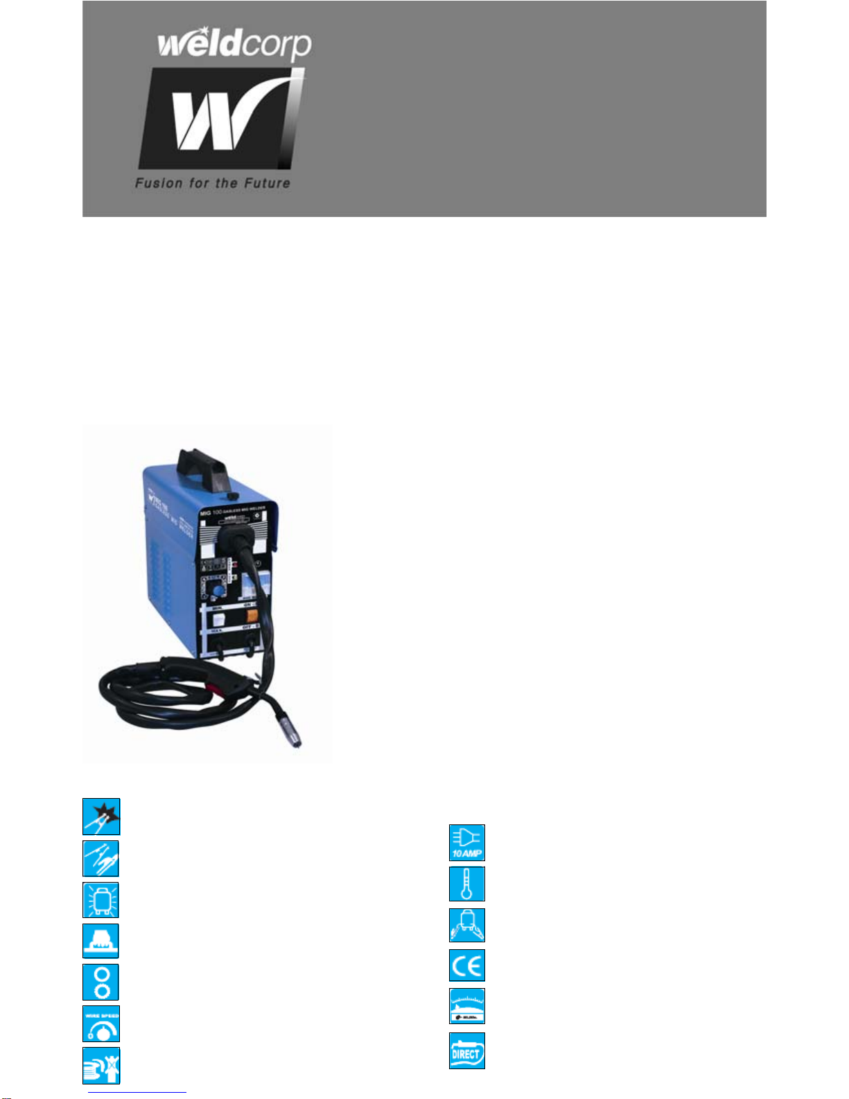
WeldCorp MIG 100 Operation manual
Other WeldCorp Welding System manuals

WeldCorp
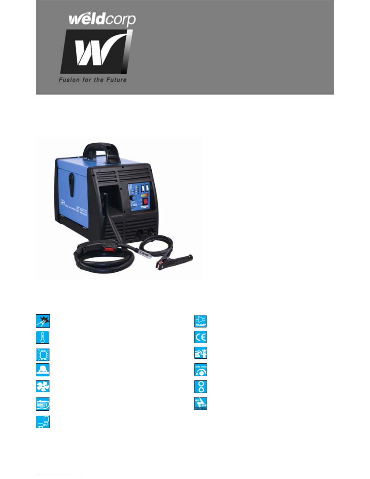
WeldCorp Mig 160 Operation manual

WeldCorp
WeldCorp WCPC001 Operation manual

WeldCorp
WeldCorp INVERTER TIG140 Operation manual

WeldCorp
WeldCorp MULTI PULSE PRO 240 Operation manual

WeldCorp
WeldCorp TIG PRO 170 Operation manual

WeldCorp
WeldCorp MIG 100 Operation manual

WeldCorp
WeldCorp ARC 140 AMP Operation manual

WeldCorp
WeldCorp INVERTER 80 Operation manual

WeldCorp
WeldCorp ARC 140 Operation manual
Popular Welding System manuals by other brands


Hobart Welding Products
Hobart Welding Products AirForce 375 owner's manual

GF
GF MSA 330 instruction manual

Hakko Electronics
Hakko Electronics FX-888D instruction manual

Abicor Binzel
Abicor Binzel ABIPLAS WELD 100 W operating instructions

EWM
EWM Taurus 355 Basic TDM operating instructions

Thermal Dynamics
Thermal Dynamics PakMaster 100 XL plus operating manual