NURIS LN 350 Quick start guide

08/2022 Rev. 1.1
OPERATIONAL MANUAL
LN 350
EN

08/2022 Rev. 1.1
All rights reserved by Nuriş Teknoloji A.Ş. Reproduction of all or any part of this document is
prohibited without the written permission of Nuriş Teknoloji A.Ş. Information and images in this
document are subject to change without notice by Nuriş Teknoloji A.Ş.

08/2022 Rev. 1.1
i
CONTENTS
Contents ...............................................................................................................................................i
Safety ..................................................................................................................................................ii
Electr omagnetic Compatibility (EMC) ......................................................................................................iii
Techni cal Spe cifications ........................................................................................................................ iv
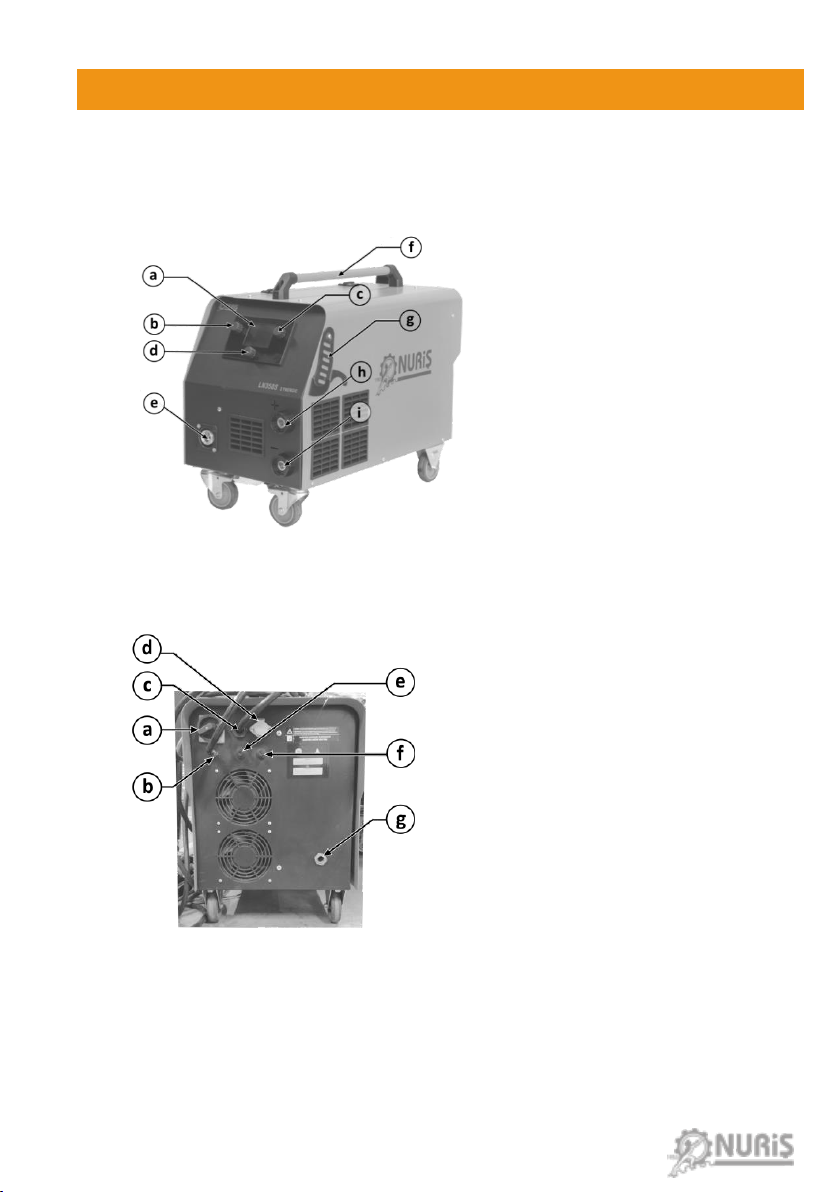
1.Intr oduction....................................................................................................................................... 1
2.Conne ction Guide ............................................................................................................................... 2
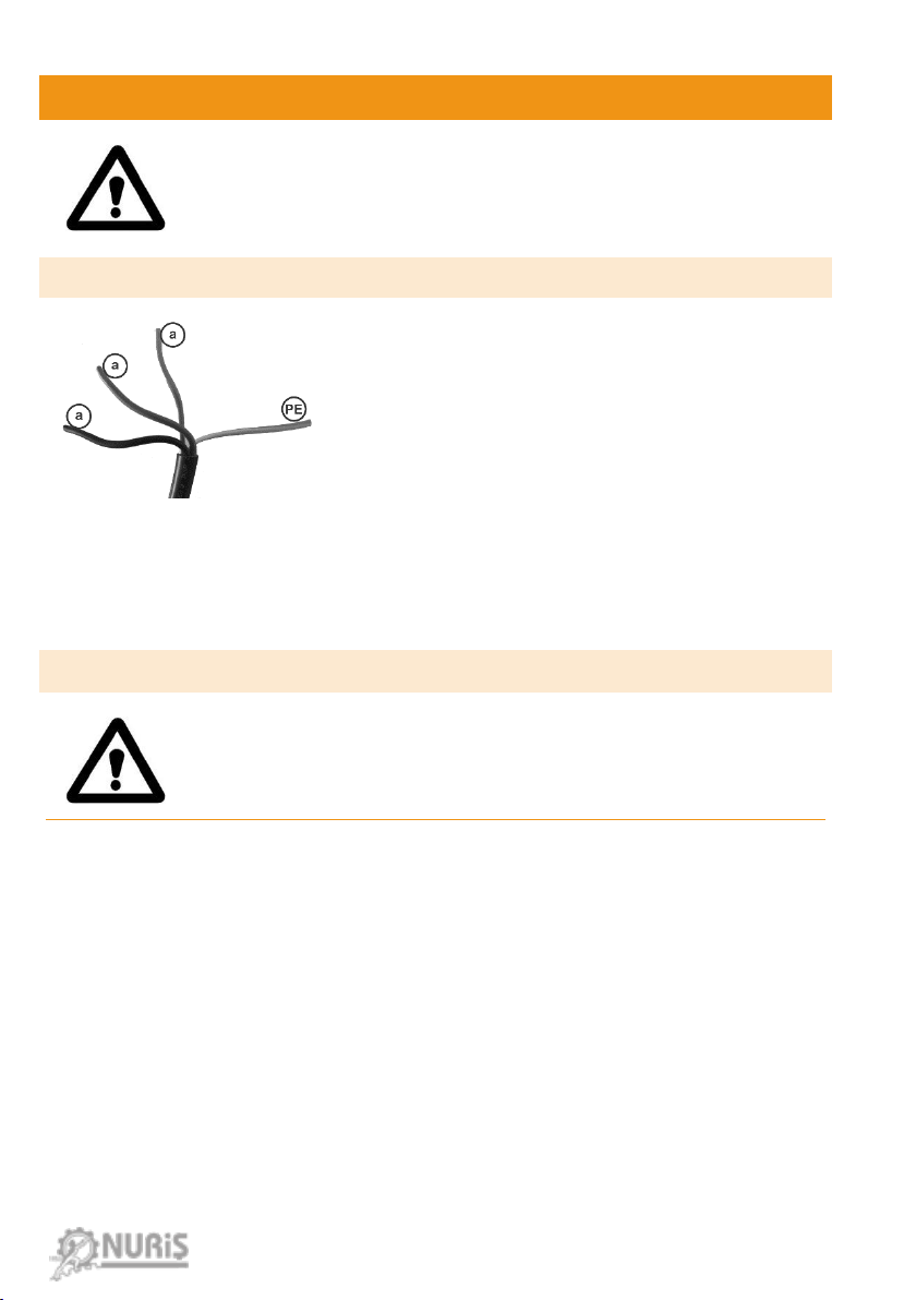
2.1. Pow er Connection....................................................................................................................... 2
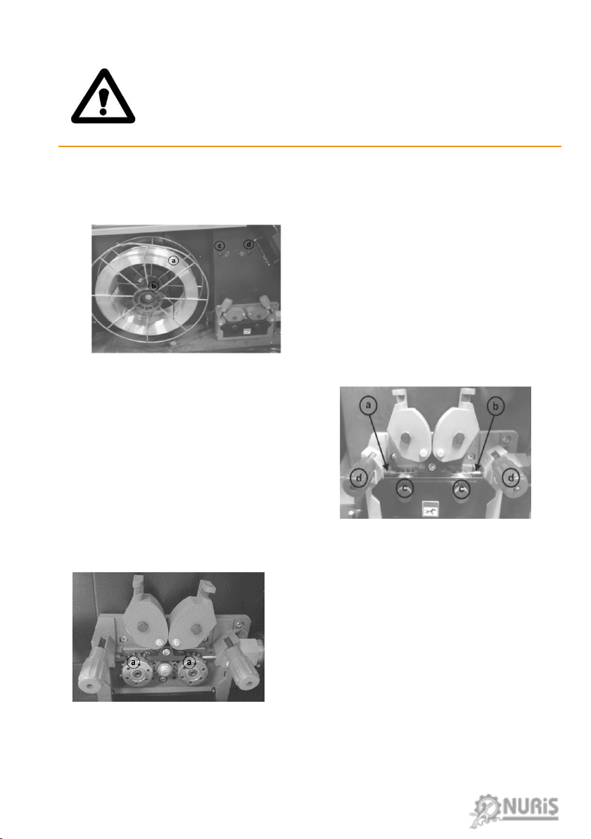
2.2. Conne ction of the Welding Wir e ................................................................................................... 2
2.2.1 Placing the Wir e Spool .......................................................................................................... 2
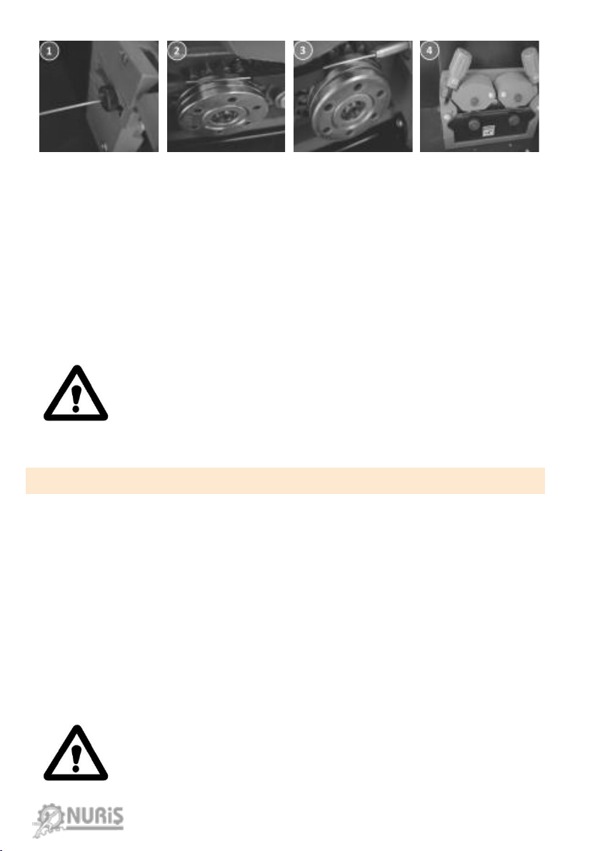
2.2.2 Wir e Feeding System............................................................................................................. 3
2.3. Gas connection........................................................................................................................... 4
3.Stor age and Installation....................................................................................................................... 5
3.1. Stor age and Oper ation Environment.............................................................................................. 5
3.2. Tr anspor tation ........................................................................................................................... 5
3.3. Installation ................................................................................................................................ 5
4.Oper ation.......................................................................................................................................... 6
4.1. Sele cting Syner gic Pr ograms......................................................................................................... 6
4.2. Symbols and Meanings ................................................................................................................. 8
4.3. Settings..................................................................................................................................... 9
4.4. Pr ogr ams..................................................................................................................................11
5. Maintenance and Trouble Shooting......................................................................................................11
5.1. Per ıodic Maintenance.................................................................................................................12
5.1.1. Daily Maintenance ..............................................................................................................12
5.1.2. Quar ter ly Maintenance........................................................................................................12
5.1.3. Semi-Annually Maintenance .................................................................................................12
5.2. Non-Per iodic Maintenance ..........................................................................................................12
5.3. Possible Pr oblems and Error s.......................................................................................................13
5.3.1. Err or Messages and Meanings ...............................................................................................15
6. Tr anspor tation .................................................................................................................................16
7. Manufactur er Company......................................................................................................................16
8. Ser vice............................................................................................................................................16

08/2022 Rev. 1.1
ii
SAFETY
Please read this manual carefully before operating the equipment. This device
should be used only by qualified personnel. Safe operation is only possible with
understanding thepossible risksfor health and correct operationof the device.
Nuriş Teknoloji is not responsible for any injury, death, or malfunction of the
device due to the improper use or lack of understandingfor the identifiedrisks.
ELECTRIC SHOCK CAN KILL: Arc welding machines can generate high voltages
during the operation. Do not touchthe live parts such aselectrode clamp, work
clamp or electrode. Always use the insulated part of the electrode clamp. Wear
protective insulating gloves to prevent riskof electric shock. Do not touch any
damaged cables.
FUMES AND GASES CA N BE DA NGEROUS: Welding may produce fumes and
gases hazardous to health. Avoid breathing these fumes and gases. To avoid
these dangers, the operator must use enough ventilation or exhaust to keep
fumes and gases away fromthe breathing zone.
ARC RAYS CAN BURN: Use a shield with the proper filter and cover plates to
protect your eyes from sparks and the rays of the arc when welding or
observing. Use suitable clothing made fromdurable flame-resistant materialto
protect you skin and that of your helpers. Protect other nearby personnelwith
suitable, non-flammable screening and warn them not to watch the arc nor
expose themselves to the arc.
WELDINGSPARKS CAN CAUSE FIRE OR EX PLOSION: Remove fire hazards from
the welding area and have a fire extinguisher readily available. Welding sparks
and hot materials from the welding process can easily go through small cracks
and openings to adjacent areas. Do not weld on any tanks, drums, containers,
or materialuntilthe proper stepshave been taken toensure that no flammable
or toxic vaporswill be present.
ELECTRIC AND MAGNETIC FIELDS MAY BE DANGEROUS: Electric current
flowing through any conductor creates electricand magnetic fields (EMF). EMF
fields may interfere with some pacemakers, and welders having a pacemaker
should consult their physician before operating thisequipment .
WELDED MATERIALS CAN BURN: Welding generates a large amount of heat.
Hot surfaces and materials in work area can cause serious burns. Use gloves
and pliers when touching or moving materials in the work area.

08/2022 Rev. 1.1
iii
ELECTROMAGNETIC COMPATIBILITY (EMC)
This machine has been designed in accordance with all relative directives and norms. However, it
may still generate electromagnetic disturbances that can affect other systems like
telecommunications (telephone, radio, and television)or other safetysystems. These disturbances
can cause safety problems in the affected systems. Read and understand this section to eliminate
or reduce the amount of electromagnetic disturbance generated by this machine.
Before installing the machine, the operator must check the work area for any devices that may
malfunction because of electromagnetic disturbances. Consider the following:
Input and output cables, controlcables, and telephone cables that are in or adjacent to
the work area and the machine,
Radio and/or television transmittersand receivers,
Computers or computer-controlled equipment,
Safety and controlequipment for industrialprocesses,
Personalmedical devices like pacemakers and hearingaids,
Equipment for calibration and measurement.
Check the electromagnetic immunity for equipment operating in or near the work area.
The operator must be sure that all equipment in the area is compatible. This may require
additionalprotection measures.
The dimensions of the work area to consider will dependon the construction of the area
and other activities that are takingplace.
If any electromagnetic disturbancesaredetected the operator must put in place corrective actions
to eliminate these disturbances. Consider the following guidelines to reduce electromagnetic
emissions fromthe machine:
Connect the machine to the input supply accordingto this manual. If disturbances occur
if may be necessary to take additionalprecautions such as filtering the input supply.
The output cables should be kept as short as possible and should be positioned
together.
If possible, connect the work piece to ground to reduce the electromagneticemissions.
The operator must check thatconnectingthe work piece to ground does not cause
problems or unsafe operating conditions for personneland equipment.
Shielding of cables in the work area can reduce electromagnetic emissions. This may be
necessary for specialapplications.
WARNING: This machine has been designed to operate in an industrial area.
Unexpected EMC problems may occur during operation in other environments.
To operate in a domestic area, it is necessary to observe precautions to
eliminate possible electromagnetic disturbances.

08/2022 Rev. 1.1
iv
TECHNICAL SPECIFICATIONS
Nuriş, LN350C SYNERGIC DOUBLE PULSE, is a gas welding machine with inverter
technology that allows MIG / MAG (metal inert gas), MMA (covered electrode)
and ARGON (TIG) welding to be done with a single machine. Thanks to its
integrated wire feeding unit, it can be used easily in all kinds of welding works.
The technical specifications for LN 350 are given in the Table 1.
Table 1. LN 350 Technical Specifications
TECHNICAL PROPERTIES
UNIT
VALUE
Utility Voltage
VAC
380 V, 3-Phase, 50-60 Hz
Input Power
kVA
13.8
Welding Current
A
30-350
Open Circuit Voltage
V
70
Welding Voltage
V
15-39
Operating Regime (25°C)
%35
350 A
%100
270 A
Protection Class
IP
IP23S
Weight
kg
40
For any maintenance or repair operations it is recommended
to contact the nearest technical service center or Nuriş
Teknoloji. Maintenance or repairs performed by
unauthorized service centers or personnel will null and void
the manufacturer’s warranty.

08/2022 Rev. 1.1
1
1.INTRODUCTION
Front and rear view of LN 350 are shown in Figure 1.1 and Figure 1.2,
respectively.
a. LCD Display
b. Welding Current/Wire
Speed and Material
Thickness Adjust Button
c. Welding Voltage Adjust
Button
d. Menu/Program Button
e. Welding Torch Connector
f. Handle
g. Torch Bracket
h. Electrode Clamp (“+”
outlet)
i. Earth Clamp (“-” outlet)
Figure 1.1. LN 350 (front view)
a. On-Off Switch
b. Gas Inlet Coupling
c. Three Phase Electric
(Power) Supply Input
Union
d. Heater Power Connector
e. Wire Feeder Engine
Protection Fuse
f. Gas Heater Protection
Fuse
g. Continual Wire Input
Figure 1.2. LN 350 (rear view)

08/2022 Rev. 1.1
2
2.CONNECTION GUIDE
WARNING: The installation and first operation of the machine
should be done by authorized technical personnel.
2.1. POW ER CONNECT ION
Welder power supply works with three phase 380
Volt 50Hz utility power. The energy input cable
is located at the rear of the welder power
supply. The yellow-green cable (Figure 2.1-PE)
should be connected to protective earth. The
remaining cables are the three phase
connections (Figure 2.1-a). The phase order is
not important, thus, connect the three phase
cables to the phase supply of the utility.
Figure 2.1. Pow er Connection
2.2. CONNECT ION OF THE W ELDING W IR E
Before installing the welding wire, wear gloves to prevent
corrosion of the wire and injury to your hand.
2.2.1 PL ACING TH E W I RE S POOL
The wire adapter shown in Figure 2.2-b is opened by turning it. The welding
wire reel is placed in the wire feeder unit of the welding machine with the wire
coming from below and the adapter is tightened again.
Gas Button (Figure 2.2-c): During gas cylinder replacement or gas related
connections, the gas valve can be opened by pressing this button. Thus, it can
be checked whether the gas is coming smoothly or not.
Wire Feeding Button (Figure 2.2-d): This button is used to ensure that the wire
feeder motor rotates during the insertion of the welding wire. When the wire
is finished, the wire should be driven by pressing this button until the wire
comes out of the tip of the torch after the new wire is inserted.

08/2022 Rev. 1.1
3
Tightening the screw too much can slow down the speed of
the wire being fed and cause machine malfunctions, while
under tightening the screw can cause the wire spool to
become tangled. Therefore, the tightening of the screw nut
must be well adjusted for a nice and effective weld.
2.2.2 W IRE FEEDING S YST EM
In Figure 2.2, the view that will appear when the cover of the wire feeder is
opened is shown.
After placing the welding wire
reel(2.2-a) it is passed through the
wire channel and brought to the
entrance of the wire feeding.
Figure 2.2. Wire Feed Mechanism
The reel screws in Figure 2.3. -c are
unscrewed and removed. After the
screws are unscrewed, the fixing
cover of the wire feeder reel drops
automatically and the wire drive
reels are reached.
Figure 2.3. W ire Feed Motor
The wire drive reels are shown in
Figure 2.4. The reels are marked
according to the wire diameter used.
Select the wire drive reels according
to the thickness and type of wire you
will use. V-grooved wire feed reels
are used for steel and stainless steel
and U-grooved ones are used for
aluminum. Also corrugated V-
grooves are used for cored wires.
Figure 2.4. Control Panel

08/2022 Rev. 1.1
4
The welding wire is stretched from the 1st guide shown in Figure 2.5 and driven
onto the wire reel. The wire passed through the guide is inserted into the wire
drive reel channel as shown in Figure 2.5-2. The wire passed through the reels
is passed through the direction guide as in Figure 2.5-3, and the manual driving
process is completed. After the manual driving process is completed, overprints
are closed(Figure 2.4-4). By pressing the wire feed button, the wire is fed until
the wire comes out homogeneously from the tip of the torch.
If the pressure setting is too high, crushing may occur on the
wire. The round structure of the wire may be disrupted and
problems may occur while passing through the torch. In
addition, the problem of clogging in the contact nozzle may be
encountered. If the pressure is low, the wire will be loose and
the wire feeding will not be homogeneous. When adjusting the
pressure, it is done from loose to tight.
2.3. GAS CONNECTION
Argon or Argon + Helium is used for welding aluminum, magnesium, copper and
their alloys of non-ferrous metals, and Argon + Oxygen mixed gases are used for
welding stainless steels.
The oxygen ratio must never exceed 3% in welding stainless steels .
Attach the gas connection hose and regulator to the tube, loosen the
adjustment screw and turn on the gas and adjust the gas flow by tightening the
adjustment screw. If CO2 gas is to be used, a CO2 heater should be connected.
There is a power plug for the CO2heater at the rear of the welding power unit
(Figure 1.2-b).
WARNING: The 220 Volt 120-Watt socket located at the back
of the machine is only for the heater. Do not use it for other
purposes. It can damage the machine.
Figure 2.5. W ire Feed System

08/2022 Rev. 1.1
5
3.STORAGE AND INSTALLATION
3.1. S TORAGE AND OPERATION ENVIRONMENT
The machine should be stored in a closed and dry environment between
-30 oC and +55 oC.
It should be kept upright and nothing should be put on it.
Operating temperature must be between -25 oC and +40 oC and it should
be operated in a dry environment.
Make sure that the machine can breathe easily while working.
Dirt and dust in the environment should be at minimum.
3.2. TRANS PORTATION
Always use the handles when moving the machine.
Never pull on cables, torch or hoses.
Before moving make sure that the machine is turned off and
disconnected from the grid.
Before transporting, remove all interconnections.
Gas cylinders and small parts must be transported separately from the
machine.
Chains and/or ropes to be used during transportation should be of equal
length, equal load distribution should be ensured and the machine
should be lifted in a balanced way.
The relevant regulations of the country of use, occupational safety and
accident prevention rules should be taken into account.
During transport, nobody should be in the dangerous area under the
machine.
3.3. INSTALLATION
Put the welding machine in a place that you can easily access during
work.
The welding machine should not be close enough to adversely affect
the operation of the operator.
The machine must be placed in a way it can easily breathe from the air
inlets.
Make sure that the environment is not wet and too humid.

08/2022 Rev. 1.1
6
Make sure that the dust and dirt that can get into the machine are kept
at minimum.
Cables should not be stacked on top of each other, cables and machine
should be on the same side of the operator and as far away from the
operator as possible. Cables should not be around the operator and
scattered around.
The gas cylinder should be away from the welding area, should not get
hot and should not be affected by welding sparks.
The machine should not be placed near electromagnetic devices during
operation and storage.
The machine should not be placed in places with a slope of more than
10°. Make sure that the machine is stable before use.
4.OPERATION
4.1. S ELECTING SYNERGIC PROGRAM S
Synergic programs can be used in two ways: manual (selecting from the list)
and automatic (according to the material to be welded, type of welding wire
and gas type).
Figure 3. Control Panel

08/2022 Rev. 1.1
7
To automatically adjust the synergistic program, use the adjustment button
(Figure 1.1d) to enter the section below.
Here, the user should select;
●The material to be welded,
●Wire type,
●Wire diameter,
●Protective gas,
●Pulse sections, respectively.
When the program number is seen on the screen after the selections are made,
the determined program can be saved by pressing the setting button in Figure
1 again, and it can be canceled by pressing the right or left adjustment button.
Figure 4. Settings Menu
Figure 5. Settings Menu

08/2022 Rev. 1.1
8
To select the synergic program from the list, enter the side tab where the
programs can be examined.
In synergic programs, by pressing the button and switching to the section
the thickness of the part to be welded can be adjusted. In this case, the
synergistic program will automatically adjust the current and voltage values.
When the welding is not as desired, current and voltage values can be adjusted
manually. Voltage adjustment can be made by using the Welding Voltage Adjust
Button (Figure 1.1-c).
4.2. S YMBOLS AND MEANINGS
After selecting the synergic program, the following features should be set.
Torch Setting
The torch is set to 2T. Welding starts when the trigger
is pressed and continues until you release it.
The torch is set to 2T Smart. Welds while holding the
trigger, stops when released. In addition, if the trigger
is briefly pressed and pulled, it switches between the
saved smart programs.
The torch is set to 4T. Welding starts when you press
and release the trigger, and stops when you press and
release it again. If the trigger is held down before
stopping the weld, crater fill function works.
The torch is set to 4T Smart. Welding starts when you
press and release the trigger, and stops when you
press it again. In addition, if the trigger is briefly
pressed and pulled, it switches between the saved
smart programs.
Inductance Setting
Increasing the inductance makes the welding more
wide, lowering it makes it more collective.

08/2022 Rev. 1.1
9
Pulse Setting
Pulse, is a property that changes the welding
characteristic. Preferred when welding more
sensitive materials. Provides low heat input and less
spatter.
Water Motor
It is the symbol indicating whether the water motor
is on or off. The water motor should be turned off
when the air-cooled torch will be used, and should
be left on when not in use.
Material Thickness
It is the symbol indicating the thickness of the
material to be welded.
4.3. S ETTINGS
The Settings Tab provides detailed settings for the welding. Information about
these settings is given below.
Figure 6. Settings Tab

08/2022 Rev. 1.1
10
Wire burn-back time: The duration of the arc while the wire stops at the
end of welding. If the time is kept short, the wire may stick to the material.
In very long times, the wire may stick to the torch.
Pre-gas time: Sets the duration of the shielding gas that starts to be given
before welding starts.
Post-gas time: Sets the duration of the shielding gas that continues to be
given after the welding process is finished.
Initial wire speed: The speed of the wire going into the material until the
welding wire touches the material to be welded and starts the welding.
Soft start: After welding starts, the time to reach the set wire speed from
the initial wire speed.
Crater fill time: Sets the crater fill time when welding is complete.
Crater fill ratio: Adjusts the ratio of end current to main current during
crater fill.
Hot start ratio: When starting the welding process, a hot start ratio
multiplier is applied to the main current, so that the welding process starts
at a higher current value, thus allowing the cold material to be welded and
the welding wire to heat up quickly.
Water motor stop: When the dry torch is used, if this setting is set to 1,
the water motor will not start.
2P Active: Double pulse on and off setting.
2P Frequency: Determines the double pulse frequency. The higher the
frequency, the faster the upper current and lower current changes.
2P Occupancy ratio: Sets the ratio of the dwell time in the upper current
of the double pulse to the dwell time in the lower current.
2P Amplitude: Adjusts the amplitude between the upper current and the
lower current of the double pulse.
Smart trigger programs: It is used to call the saved programs with the smart
trigger function in case of welding or not.

08/2022 Rev. 1.1
11
Manual wire speed: While attaching the wire, it adjusts the speed of the
wire supplied with the wire feed button.
4.4. PROGRAMS
The synergic program, manual mode and all other settings can be saved and
accessed at any time from this section. Current program (10 separate programs)
can be saved or pre-recorded programs can be accessed from this screen.
5. MAINTENANCE AND TROUBLE SHOOTING
Before starting the maintenance, disconnect the machine from
the power supply and make sure that there is no voltage on it.
Maintenance can be done by the user.
All the electrical connections should be checked regularly.
Maintenance, repair or any modification to the machine cannot be made by
applying different or incorrectly what is described in this manual.
Repairs and modifications should only be carried out by authorized persons
in order to prevent possible injuries and damage to the machine.
The machine may be out of warranty as a result of unauthorized
intervention.
The device does not require maintenance in the specified conditions, but
some points should be considered for its high efficiency and long-lasting
operation.
Figure 7. Programs Tab

08/2022 Rev. 1.1
12
The periods specified below are the periods to be followed in case the
device does not encounter any problems. These periods can be shortened
according to the density and pollution of the working environment.
5.1. PERIODIC MAINTENANCE
5.1.1. DAILY MAINTENANCE
Before operating the machine, the electrical power supply cable and
welding
cables must be visually inspected. If there is any crushing, peeling or
breakage in the cables, the service should be notified.
Check whether the welding cables and torch terminals are tight and
suitable. Tighten if loose.
Daily maintenance should be done by the person who will perform the
welding process.
5.1.2. QUARTERLY MAINTENANCE
Crushed, frayed or broken cables or cords should be maintained and
replaced with new ones if necessary.
5.1.3. S EM I-ANNUALLY MAINTENANCE
Electrical power supply connectors must be checked and tightened if
loose.
Side caps should be opened and all energy connections here should be
tightened.
All accessible bolts and nuts should be checked and loose ones should be
tightened in the body and other parts of the machine.
Dust accumulated in the machine should be cleaned with compressed dry
air. If the machine is used in very dirty environments, this process should
be done in periods shorter than six months.
5.2. NON-PERIODIC M AINTENANCE
The consumables on the torch should be cleaned regularly and replaced if
necessary.
For a good welding quality, if the welding wire is rusted or corroded, it
should be replaced with a new one.
If the labels on the device are dirty and difficult to read, clean them.

08/2022 Rev. 1.1
13
5.3. POSSIBLE PROBLEMS AND ERRORS
PROBLEM
POSSIBLE CAUSES
Wire drive reels spins but wire
does not come through
* The compression spring pressing the
wire feed spools are not in place or is
loose.
* The torch lead is bent excessively
or the spiral guide inside the torch is
clogged.
* The contact part is blocked.
* Depending on the wire diameter
used, the wrong groove was used in
the wire feed spool.
* The wire is not placed correctly in
the spool groove.
* Suitable welding wire is not used.
Irregular wire feed
* The contact part is deformed.
* The wire feed spools are dirty or
worn.
* Wrong groove is used in the wire
feed spool.
* The spiral guide inside the torch is
clogged.
* Suitable welding wire is not used.
The arc does not start
* Earth clamp not connected
correctly.
* The contact part is deformed.
Long and unstable arc
* Welding voltage is of high value
according to wire diameter and wire
feed speed.
Powerless arc
* Welding voltage is of high value
according to wire diameter and wire
feed speed.

08/2022 Rev. 1.1
14
Droplets are splashing
* The voltage is too high.
* The gas nozzle is not cleaned
properly.
* Wire speed is set incorrectly.
Insufficient welding filling
* Welding speed is higher than it
should be.
* Wire feed speed is lower than
welding speed.
* Wire diameter is not suitable for
the job.
WELDING PROBLEMS
POSSIBLE CAUSES
Porous welding
* The gas level is too low or too
high.
* Splashed droplets accumulate in
the gas nozzle and cause insufficient
gas flow.
* The air flow in the welding area
neutralizes the shielding gas.
* The distance between the tip of
the torch and the material being
welded is too large or the torch is
being used incorrectly.
* The material to be welded may be
moist, oily, rusty.
* Wrong shielding gas used.
Bad welding filling
* Irregular use or incorrect contact
part is used.
* Low welding voltage selected.
* Irregular welding speed used.
Uneven welding
* Wire speed is very high compared
to the voltage value.
* Welding speed is very low.
Penetration is insufficient
* Wire feed speed is very low
compared to voltage.
Table of contents
Languages:
Other NURIS Welding System manuals
Popular Welding System manuals by other brands

Magmaweld
Magmaweld Monomig 200ik user manual

Ahlmer Maschinen & Gerätebau
Ahlmer Maschinen & Gerätebau Standard 400E user manual

EWM
EWM Cool XQ 40 operating instructions

BossWeld
BossWeld TREO 175 user manual

PlasmaPart
PlasmaPart Cut 55CI Eclipse Operation & safety manual

BorMann
BorMann Technik BWM3063 owner's manual