Weldex WDR-4405MC User manual

User Manual
Product Name : HDD Mobile DVR
Product Model : WDR-4405MC(Rev.2)
Version : V1.0

1
Content
1. introduction ................................................................................................................................... 2
1.1. Purpose of writing...........................................................................................................2
1.2. Security alert....................................................................................................................2
2. Product Introduction .....................................................................................................................3
2.1. Product Overview ...........................................................................................................3
2.2. Main Feature ...................................................................................................................3
2.3. Specification ....................................................................................................................4
2.3.1. List of Product Function Specification....................................................................4
2.3.2. Product performance parameters.............................................................................5
2.4. Product characteristics ..................................................................................................5
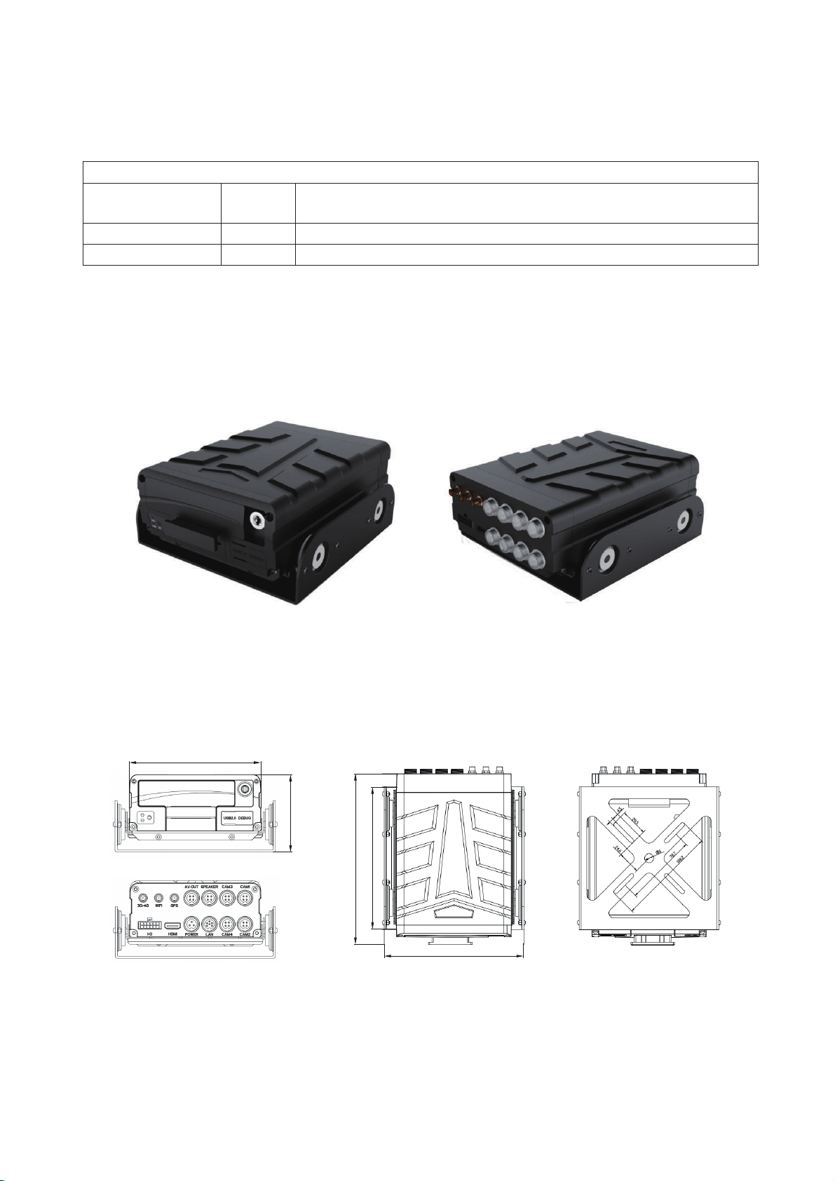
2.4.1. MDVR outlook........................................................................................................5
2.4.2. MDVR size and installation holes...........................................................................5
2.4.3. Front panel and back panel......................................................................................6
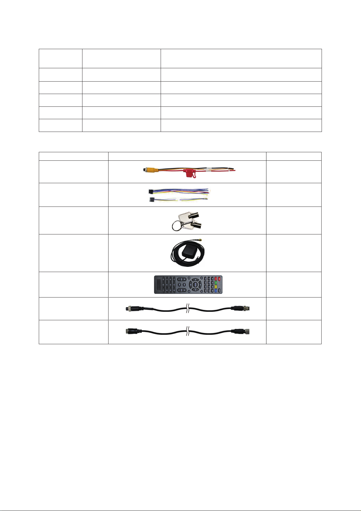
2.4.4. Accessories ........................................................ ......................................................7
3. MDVR Installation Guide............................................................................................................. 7
3.1. Preparation before installation ......................................................................................7
3.2. Wiring method.................................................................................................................8
3.3. Booting ............................................................................................................................. 8
4. MDVR Operation Guide ............................................................................................................... 9
4.1. Remote Control Function Key Guide........................................................................... 9
4.2. Main menu framework .................................................................................................10
4.3. Operation and configuration........................................................................................10
4.3.1. User login.............................................................................................................. 10
4.3.2. System operation and configuration......................................................................10
5. Common Shortcut Settings and Solutions for Possible Issues ....................................................27
5.1. Shorcut settings ............................................................................................................ 27
5.1.1. Wiring test and boot ..............................................................................................27
5.1.2. IO serial port usage ...............................................................................................27
5.2. Related issues...............................................................................................................28
5.2.1. Why no record after the device is turned on?........................................................28
5.2.2. Why does the mdvr restart frequently when installed in the car?.......................... 28
5.3. GPS related issues.......................................................................................................29
5.3.1. Why can't I see the GPS location information on the device?...............................29
5.3.2. The device is online, why can't I see the vehicle location information? ...............29
5.4. Appendix ........................................................................................................................30

2
1. introduction
1.1. Purpose of writing
WDR-4405MC(Rev.2) User Manual was written to enable users to master the
features and functions of this product with the help of this manual, to correctly install
and use the product, and to facilitate the daily work of technical support engineers and
the maintenance work of product engineers.
1.2. Security alert
To ensure users can use this product for a long time, safely and
satisfactorily, please read the following warnings carefully before installing and
using this product:
All installation and maintenance must be performed by professional technicians
The normal working voltage range of the device is DC 8V~36V. Please note that
the power input should not be connected reversely. Please ensure the stability of
the power input line. The output cannot be short-circuited.
The device outputs 12V external voltage, which is only used for camera power
supply. It is not allowed to connect any non-recommended equipment.
Correctly connect the ground wire of the device to the ground wire of the vehicle
to form a loop.
The equipment should be installed in a dry and ventilated environment to avoid
moisture, rain and vehicle cleaning and flushing position, keep the equipment
away from heat, dust and strong magnetic field.
Please install the equipment as far as possible on the vehicle where the vibration
is weak, to improve the stability of the equipment and prolong the service life.
Do not stack debris within 20cm around the installation equipment, and do not
have heavy objects on it to ensure the heat dissipation.
The storage devices and modules on the device do not support hot swap. Do not
insert or remove storage devices or modules while the device is powered on.
Please perform regular maintenance on the storage device( hard disk or SD card):
copy the video data to the computer and format it to protect and extend the
performance and service life of the storage device.
Do not open or disassemble the equipment without the guidance of a professional
technician.

3
2. Product Introduction
2.1. Product Overview
WDR-4405MC(Rev.2) is a cost -effective, scalable device specially designed for in-
vehicle video surveillance and remote monitoring. It adopts high-speed processor and
embedded operating system, combined with the most advanced H.264/H.265 video
compression/decompression technology and GPS positioning technology in the IT
field. WDR-4405MC(Rev.2) supports up to 4 channels 1080P recording, with 5
recording formats (CIF/D1/960H/720P/1080P optional) to record the driving
information locally.
WDR-4405MC(Rev.2) products are simple and elegant, with super vibration resistance,
flexible for installation, powerful and reliable.
2.2. Main Feature
Function
Function Description
Video
1. Support 1~4 channels of real-time audio and video local
recording;
2. Supported recording mode (taking PAL as an example):
4 ch CIF, 25 FPS; 4 ch D1, 25 FPS; 4 ch 960H, 25 FPS;
4 ch 720P, 25 FPS; 4 ch 1080P, 25 FPS;
3. Support PAL system, NTSC system;
4. Support recording OSD overlay, such as time, channel name,
license plate number, GPS, speed
5. Support storage device automatically overwritten when full
and
alarm video file protection
Storage
Hard disk supports 2TB capacity, SD card supports 256GB
capacity
Playback
1.Support local 4-channel audio and video sync playback
2. Support PC Client playback and analysis
3. Support traditional playback functions such as play, pause,
slow play, fast forward, fast backward
Vehicle record
1. It can record driving information such as vehicle speed, GPS
data and oil quantity;
2. Alarm linkage can be realized through the reserved 4pcs I/O
input ports;
3. Support local records, view driving information

4
2.3. Specification
2.3.1. List of Product Function Specification
Specification Parameter
System
Operation language
English
Operation interface
Graphic operation interface(OSD menu)
Password security
Two-level administration:User/Administrator password
Video
Video input
Support 4CH D1/720P/1080P AHD video mixed inputs
Video output
1ch video output(V-OUT), 1ch HDMI video output
TV system
NTSC / PAL (NTSC@120 frame 1080P / PAL@100frame 1080P)
Image compression standard
H.264 / H.265 main profile
Resolution
Support 1080P, 720P, 960H, D1, CIF
Dual stream
Support
Video display
1ch/4ch display; Supports full screen display of event triggers
Audio
Audio input
4ch audio input
Audio output
1ch audio output(A-OUT)
Recording method
Synchronous recording in audio&video
Image
processing&storage
Local record format
CIF / D1 / 960H / 720P / 1080P optional
Video streaming standard
ISO14496-10
Video bitrate
CIF:512Kbps ~ 128Kbps,
D1/960H : 1536Kbps ~ 512Kbps (recommend spec)
720P : 3072Kbps ~ 768Kbps
1080P: 5120Kbps ~ 1024Kbps,
4 grades optional, Highest : Best / Lowest : general
Audio bitrate
40KB/s
Data storage
Standard : 1x SATA HDD/SSD 1TB, up to 2TB; and 1x SD card, up to 256GB
Alarm
Alarm input
4ch alarm input
Alarm output
2ch alarm output, highest output level: 12V
RS232 interface
Support
RJ45 Network interface
Support 1*6 pin aviation port to RJ45 network interface, support local
network connecting with server
USB interface
Support 1*USB interface for software upgrading and record file copy
IR interface
IR extension interface,support remote control data reception
GPS system
Support build-in GPS module; geographic coordinates and speed could be written into coding streaming.
G-sensor
Build-in G-Sensor; support triaxial motion detection and user setting of X, Y and Z coordinates
Matching software
Playback analysis in PC
Video playback in PC, and analyze vehicle info in files
Software upgrading Upgrading maintenance
USB / Hard disk / SD card upgrading
Dimension
Dimension
153.0(W)
x74.0(H) x187.4(D) mm

5
2.3.2. Product performance parameters
2.4. Product characteristics
2.4.1. MDVR outlook
Front panel Back panel
Electrical parameter
Power input 8 ~ 36V
Power input:
+
8V
~+
36V; always < 8V or >36V, auto power-off will start and enter into
protect mode.
Power output
12V
Power output: 12V
(
+/-0.2V
)
; max current 1A
Operating temperature
-20°C ~ +80°C
Referring to excellent ventilation conditions
2.4.2. MDVR size and installation holes
125.6
[BACK][TOP][BOTTOM]
74.0
156.0
187.4
[FRONT]
153.0

6
2.4.3. Front panel and back panel
Front panel definition as below shown:
Panel classification
Definition
Hard disk box, sd card slot
It is hard disk, sd card
Led indicator light
Show device operating status
IR
Receive remote control keys
Hard disk lock
Unable to start without locking the device.It will automatic
HDD case, SD card
LED light
HDD lock
USB and Debug
Front panel
standby once you open the lock during the using.
USB
Used for firmware upgrading and video file export and
mouse operation
Debug
Device software debugging interface
Back panel definition as below shown:
Back panel
Interface Name Description
Power Power input interface 8V~36V wide voltage power input interface
GPS GPS antenna interface GPS antenna interface

7
I/O
Alarm input and output
interface, I/O interface
Alarm input and output interface (input high level >
4V and low level < 3V valid, alarm output +12V)
AV-OUT Audio & video output
Display output interface(connect to monitor)
LAN IPC interface IPC/ local network interface
Speaker Intercom interface Intercom interface for remote intercom
HDMI HDMI output interface HDMI output interface
CAM 1-4 Camera input interface Camera input interface
3. MDVR Installation Guide
3.1. Preparation before installation
1. Tools: cross screwdriver, set copper wrench, electrical waterproof tape, cable tie,
wire stripper (oblique pliers), needle-nosed pliers, 12V---36V test pencil (multi-
meter) and so on.
2. Make sure that there is a storage medium(SD card/hard disk) for recording storage.
3. Select the location where the terminal equipment is installed: mainly consider the
wiring safety and convenience of installation, avoid high temperature, ensure
2.4.4. Accessories
Description
Picture Quantity(PCS)
Power cable 1
I/O cable 1
Key 2
GPS
antenna(optional) 1
Remote
con
trol(optional) 1
External camera
interface cable
External AV-out
interface cable
4
1
( Truck )
( Car )

8
waterproof and shockproof.
a) Waterproof: choose a location that is not easy to enter the water, and keep
away from the air conditioner as much as possible to prevent condensation from
accumulating inside and outside the terminal equipment when the temperature
changes, which seriously affects the service life of the product;
b) Shockproof: the terminal cannot be suspended or installed in a long-term
vibration position;
c) Anti-high temperature: the terminal should avoid the high temperature part
inside the car;
d) Wiring: some large vehicles have a total control switch. At this time, the
installation position of the terminal equipment should also consider the connection of
the power cable. The wiring should be wrapped and secured with electrical
waterproof tape and cable tie.
3.2. Wiring method
Wiring from the rear panel, details of each interface definition can be seen from 2.4.4
Rear Panel Interface Definition:
POWER: Red line connects to input positive (PWR+)
Blackline connects to input negative (PWR-)
Yellow line connects to start signal (ACC)
CAM (1-4): one port for one camera
AV OUT: GND: 12V power output negative
12VDC: 12V output positive
AUDIO: output audio signal
CVBS_OUT: output CVBS (video) signal
Note:
1. Confirm that the battery voltage is between 8-36V, otherwise the equipment will be
burned out.
2. Pay attention to the insulation of the power cable to prevent the power supply from
short-circuiting the battery.
3.The equipment power supply must take power from the positive and negative poles
of the battery, can not be grounded to make the ground, the ground will produce a
negative pulse to interfere with the normal operation of the host.
3.3. Booting
In System Settings -> Power On/Off
If it is set to ignition mode(ACC), it needs to meet three conditions to start:
a) POWER that requires POWER+ to connect to high level, PWR- to ground
b) POWER ACC connects to the ACC ignition wire of the car
c) Needs to lock the electronic lock on the front panel
When initial booting, the default isACC ignition mode

9
4. MDVR Operation Guide
4.1. Remote Control Function Key Guide
Remote control buttons and functions:
LOGIN
When the MDVR has a password, press
the LOGIN button to enter the password.
Because the system does not have a
recovery and reset function, please
remember the password.
4 screen split key
Four screen split
key
number keys
1, 2, 3, 4
Under the monitor screen, switch
between four screens and single screen.
Press the four screen split button to
display 4 screens. Under the monitor
screen, press the corresponding number
key to display the corresponding
channel on one screen: 1--channel 1; 2-
- Channel 2; 3--channel 3; 4--channel 4;
Used for digital input on the input
interface.
Up, down, left, right direction keys, PTZ
control direction keys
Auto, Preset, Call,
Zoom +, Zoom -,
Focus +, Focus -,
Aperture +, Aperture
-, PTZ, PRESET,
RECALL, BRUSH
PTZ control function key
【ENTER】
Confirm key
RETURN
Go back to the previous submenu.
Finally exit the setup menu and exit to
the monitor screen;
CANCEL Delete key / backspace
+-
Backspace and forward spacekey in edit
box; PgUp/PgDn key
F1、F2、F3、F4 Backup key

10
4.2. Main menu framework
GPS 信
4.3. Operation and configuration
4.3.1. User login
When password switch is turned on, click the menu button will pop up the login
menu, and the user needs to enter password to identify himself. As longs as
password is entered correctly, the menu interface will be automatically entered.
When password switch is turned off, click the menu button will directly enter the
setting menu, and the login interface will not pop up.
4.3.2. System operation and configuration
Description:
All the settings of the following submenus will be valid after confirming [Save],
otherwise the setting is invalid.
The digital input can be entered directly by using the number keys on the
remote control or by using a soft keyboard. Character and pinyin input must
Setup
Storage
manageme
Status
Monitor
screen
Video
search
Maintainance
Menu
Storage
device
Data export
Basic info
3/4G info
Playback
Export
Video
Display
Time&Date
User
Record
Network
Alarm
Peripheral
Vehicle
About
Parameter
Upgrade
Rebooting

11
be implemented through the soft keyboard.
Main Menu: Display all main settings: system setup, video search, disk management (storage),
system information(status), system maintenance
4.3.2.1. System setup
System management settings include below submenu: display, time and date, user,
record, network, alarm, peripherals, vehicle.
①Display setting
Device name: display device name
Device ID: input through the soft keyboard, must be unique to avoid conflict. used
to connect with CMS platform.
SYS(CVBS system): CVBS display output system
Resolution(VGA): HDMI output display resolution setting
Split screen: boot channel display
Margin set: adjust the display size
Language: set the system display language
Login duration: set the login duration. If timeout will exit the login menu and return

12
to preview
Start guide: help users understand software operations
②Time and date setting: set time and date
Date and time: set the date and time, select the date with the mouse, enter the
number keys to manually set the time
Date format: three formats, year/month/day, month/day/year, day/month/year
Time format: select time (12/24 hours) format display
Zone(GPS time synchronization): on/off. Select on, when device boots every time,
and when the GPS signal is valid, the system time error will be automatically
corrected.
DST(Summer Time): On/Off, set the daylight saving timestart timeaccording to
different regions
Time zone: drop-down selection to set time zone and time zone offset
③User settings: login password settings

13
Switch: On/Off; select Off, you can log in to the setting interface without entering
the password; when you open, you must enter the user name and password to log
in to the setting interface.
User name and password can be set by yourself (please keep your username and
password properly)
④Record setting
1. Record attribute: set record attribute
Encode format: set H264/H265 encoding format
Record stream type: select main stream or substream recording
Record file format: video file format selection (currently only .asf).
File duration: set the length of a single video file.
Pre-record duration: alarm pre-recording duration setting (max 20s) .
Delay record duration: set the delay recording time after alarm (max 20s) .

14
2. Main stream setting: set the main stream encoding and recording parameters
Main stream setting: you can set the recording enable, resolution, frame rate, image
quality, and volume.
3. Substream setting: set substream encoding and recording parameters
Sub stream settings: you can set the recording enable, resolution, frame rate, image
quality
4. Camera attribute: set camera attributions
Camera settings: you can set the recognition mode (automatic, manual), type,
resolution, system, mirror flip.
Note: the main stream, sub-stream, camera attribution settings have shortcuts

15
⑤Network setting
1. Wired network
Switch: wired network setting switch
IP : set the network IP address
Network related parameters like subnet mask, default gateway, primary DNS,
secondary DNS server can be set
2. WIFI setting
STA mode
Switch: WIFI setting switch
WIFI mode: set STA-auto, STA-manual, AP
Encryption method: set the encryption method
Password: Set WIFI password
Automatically obtain IP address: check to automatically obtain the IP address
If unchecked automatically obtain IP address, you can manually set the IP address,
subcode mask, and default gateway
AP mode:

16
Name: set the SSID name of the WIFI hotspot
Password: set the password of the WIFI hotspot
Allow networking: turn on networking (AP hotspot network)
Networking: set wired or 3/4G networking
⑥Alarm: Alarm Settings
1. I/O input: I/O input setting
I/O input: I/O enable, trigger level, linkage setting (buzzer, I/O output, snapshot,
Ch pop-up, record, etc.) can be set.
2. Speed: speed alarm setting
Speed: you can set speed alarm enable, over speed alarm, low speed alarm, parking
alarm, alarm linkage setting (buzzer, I/O output, record).
Note: The linkage setting can be set only when enabled.

17
3. G_sensor:G_sensor alarm setting
Horizontal installation: you can set forward parallel, forward vertical, reverse
parallel, reverse vertical
(1)Scene mode: you can set harsh acceleration alarm, harsh deceleration alarm,
harsh turn alarm, incline alarm, linkage setting
(2)Value mode: you can set Y reverse alarm, X direction alarm, Z direction alarm,
linkage setting (buzzer, I/O output, record)
Note: The linkage setting can be set only when enabled.
4. Motion detection setting
Motion detection: you can set the recording enable, mode, trigger value (can set
the trigger range for triggering motion detection and sensitivity), linkage setting
(buzzer, I/O output, record)
Note: with shortcuts

18
⑦Peripherals
1. RS232 serial port peripherals
Device type: select the peripheral type and select the corresponding setting for the
corresponding device.
Parameter setting: set corresponding parameters (baud rate, data bit, stop bit,
check mode, etc.) according to the corresponding peripheral devices
2. Network device
Device type: select the peripheral type and select the corresponding setting for the
corresponding device.

19
⑧Vehicle:
1. Vehicle info
Plate number: set the corresponding license plate number of the device
Driver Name:set the corresponding driver name
Phone Number:set the corresponding phone number
Company:set the corresponding company name
2. Location service
Position Mode:set device position mode(BD、GPS、or BD/GPS mixed)
Update Interval(s):set the time interval for uploading device GPS data to the
platform(for platform upload)
Other manuals for WDR-4405MC
1
Table of contents
Other Weldex DVR manuals