Weldex WDR-4405MC User manual

User Manual
Product Name:4Channel Mobile DVR
Product Model:
WDR-4405MC
Version:V1.0
0

CONTENTS
Chapter 1: Product Application and Parameter ............................................................................. 2
1.1 Brief Introduction.................................................................................................................... 2
1.2 MDVR Notice ......................................................................................................................... 3
Chapter 2: Interace Definition and Function Description ............................................................. 5
2.1 MDVR Outlook and Dimension ............................................................................................. 5
2.2 Remote Control Instruction..................................................................................................... 6
Chapter 3: System Menu Instruction............................................................................................... 7
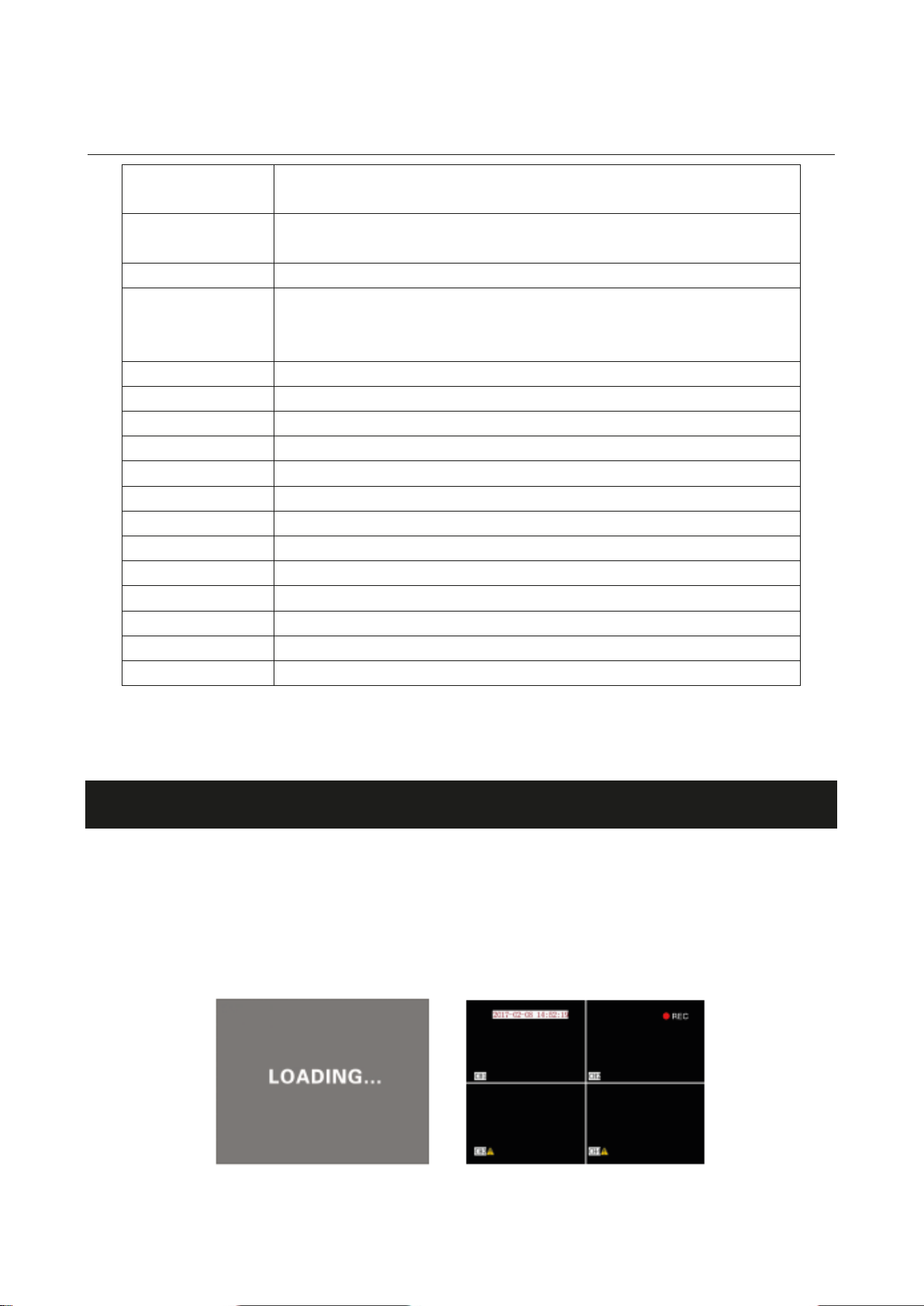
3.1 MDVR Start Up and Log In.................................................................................................... 7
3.2 System Menu Framework ....................................................................................................... 9
3.3 System Setup........................................................................................................................... 9
3.3-1 Basic Setup ................................................................................................................. 10
3.3-2 Power Setup (see Figure 3-9) ..................................................................................... 10
3.3-3 Password Setup (Figure 3-10) .................................................................................... 10
3.4 Record Setup (Figure 3-11)................................................................................................... 11
3.4-1 Normal Setup (Figure 3-13)........................................................................................ 11
3.4-2 Channel Setup (Figure 3-14) ...................................................................................... 12
3.4-3 Schedule Setup (Figure 3-15) ..................................................................................... 13
3.4-4 Sub-Stream (Figure 3-16) ........................................................................................... 13
3.5 Vehicle Info ........................................................................................................................... 14
3.5-1 I/O Setup..................................................................................................................... 14
3.5-2 G-Sensor Setup ........................................................................................................... 15
3.5-3 Speed Setup ................................................................................................................ 15
3.6 Tools...................................................................................................................................... 16
3.6-1 Configure Manage and Log Search ............................................................................ 16
3.6-2 Montion Detection ...................................................................................................... 17
3.7 System Information............................................................................................................... 19
3.8 Playback ................................................................................................................................ 19
Chapter 4: Normal Settings Shortcut Control .............................................................................. 21
4.1 Cable Connecting Test and Power On .................................................................................. 21
1
4.2 Text Input .............................................................................................................................. 21
4.3 Recording Set........................................................................................................................ 22
4.4 PTZ Connection and Setup ................................................................................................... 24
4.5 Playback Recording on Computer ........................................................................................ 25
FAQ............................................................................................................................................. 26
GPS FAQ: ............................................................................................................................ 27

Chapter 1: Product Application and Parameter
1.1 Brief Introduction
Form 1: MDVR Product Specification and Parameter
2
Item
Parameter
Specification
System
Language
English/Chinese
OSD
Graphic User Interface(OSD menu)
Password
User password/Administrator password
Video
Input
4CH composite video input
Output
Display
1CH/4CH display
Standard
PAL/NTSC
Image Compression
H.264 Main profile, 100fps
Audio
Input
4CH audio input
Output
1ch audio output(A-OUT), 1ch composite audio output
(AV-OUT)
Recording Mode
Synchronous recording in audio&video
Image
Processing &
Storage
Video format
D1/HD1/CIF optional
Video Stream
ISO14496-10
Video Bit Rate(kbps)
D1:2048 ~ 400kbps
HD1: 2048 ~ 400kbps
CIF: 1536 ~ 128kbps
8 levels settings optional, highest: level 1; lowest: level 8
Audio Bit Rate
8KB/s
Storage
Support 2.5” HDD, Max.2TB; Support 1*SD card, Max
128GB
Alarm
Input
6CH alarm input
Output
2CH alarm output, high level 12V output
Communication
Port
RS485 Interface
Support 2 RS485 interface
RS232 Interface
Support 1 RS232 interface
RJ45 Interface
Support 1*RJ45 network interface used for connecting
local network and communicating with server
USB Interface
Support 1*USB interface for software upgrading and
record file copy
Extended
Interface
Control Panel
Connect to bus station reporter or control panel
Audio Power amplifier
Support 2CH audio power amplifier output
GPS
Support built-in GPS module, Geographical co-ordinates, driving speed can be
written in coding flow
G-Sensor
Build-in G-Sensor
Software PC Playback
Play back video on computer and analyze vehi
cle information from
recording file
Software
Upgrading
Support USB upgrading, HDD upgrading and SD card upgrading
1ch video output(V-OUT), 1ch composite video
output(AV-OUT), 1ch CVBS video output(EXTENSION)

Form 2: MDVR Basic Electrical Parameter List
Item Parameter Specification
Power Input DC 8 ~ 36V +8V ~ + 36V, long time lower than 8V or above than 36V,
power off automatically and system enter protection mode
Power Output
Vehicle Key
Signal
Video Input
Impedance
Video Output
Voltage
SD Card
Interface
12V 12V(±0.2V), Max.: 2A
≤4V OFF
≥5V ON
75Ω75Ωfor each video input impedance
2Vp-p Output 2Vp-p CVBS analog signal, monitor input
impedance must fit 75Ω
I/O Interface <4V Low level alarm
≥4V High level alarm
1*SD card
1. Compatible with common brands in market; 1 SD card
supports 128GB max;
2. SD card for storage; support record and system
upgrading, ect.
Operation
Temperature -40℃- 80 ℃Natural environment, well-ventilated
3
1.2 MDVR Notice
To ensure your MDVR’s satisfactory performance and extend working life;please read and consider the
following factors before installation:
1. Please comply with all electronic products standards, vehicles’ and other connections’ installation policy when
installing your MDVR.
2. Power Supply and grounding
MDVR power supply direct input range is 8 ~ 36V DC; Please do NOT connect reversely and short circuit is
not permitted for output. Please note the power supply capacity of power cable. MDVR is still charged even when
it is shut down, so please be careful to avoid short circuit. Power supply must be disconnected before connecting
exterior devices. MDVR output is DC 12V, only to be used for camera. Please do NOT connect other electrical

4
equipment before consulting with a certified professional. MDVR sensor input mode is level. External voltage
below 4V is low level; above 4V but lower than 30V is high level; above 30V may damage device. Correctly
connect the device grounding cable to vehicle grounding cable to form a loop.If it is not in operation for long
periods of time, please cut off the power supply completely to extend MDVR life.
3. Humidity Requirements
Please install your MDVR within a dry environment to avoid moist, drip or water spray; do NOT install your
MDVR in sunken places where liquid may seep in or wet places where liquid may drop;
Please do NOT touch your MDVR with wet hands; do NOT touch your MDVR if you are standing in water or
getting into other liquids, it may cause electric shock.
4. Installation Position of the MDVR
To extend the life of the device, please install your MDVR in a place with weaker vibration, such as back of
driver’s seat. MDVR should be installed in a well ventilated place;it should be kept at least 6” (15cm) away from
other devices on the same level for better ventilation and heat emission. MDVR can NOT be installed in enclosed
spaces, such as vehicle trunk. Frontal mount or side mount is allowed.
External cables must have enough space and flame retardant protections to ensure it will not cause electrical fires
due to bending or shaking abrasions. Make sure MDVR is kept away from any heat sources and the area around
MDVR is cleared. Do NOT put anything on top of the MDVR.
5. Device Security
Make sure the driver and passengers can not intervene or damage any MDVR part, camera, cable or other
accessories. Do NOT install MDVR beside other restricted devices of vehicle. Please keep vehicle engine turned
off when installing to avoid any damage to the device.
Installation Notes:
1. MDVR contains electronic parts, please handle with care during transportation.
2. Installation and maintenance must be done by certified and trained professionals.
3. MDVR can NOT be installed in places where liquid or water erosion may occur.
4. Installation parts and accessories must be suitable to carry weight of MDVR.
5. Make sure MDVR is kept away from heat sources, dust and strong magnetic field.
6. Make sure there are no sundries on MDVR.
7. Please do NOT pour water directly onto the MDVR when cleaning the vehicle.
8. It is NOT recommended to connect other devices to MDVR power supply.
9. Please do NOT insert any objects into MDVR during its operation.
10. Please do NOT open or disassemble MDVR unless done by a trained and certified professional.
11. Replacing any module is not recommended when MDVR is working.

Chapter 2: Interface Definition and Function Description
2.1 MDVR Outlook and Dimension
Front Panel Back Panel
5
[Outlook]
[Dimension]

2.2 Remote Control Instruction
6

Power on / off Press twice the MDVR will restart.(Soft start key)
Note: this button has not been enabled yet
Login
This button is available if password has been set. Please keep your password
in safe because MDVR has no system reset function
ENTER Check system information
Channel Switching
Switching displayed channel between 4 channels and 1 channel. After
pressing this button, the switching will be: 4ch to ch1 to ch2 to ch3 to ch4
then to 4ch
Return
Back to last menu until local monitoring video
Pause / Step
Pause and step forward when playback, back to normal with “Play”
GOTO Jump to chosen point when playback
Frame Frame playing
Play Normal playing(Still display when pause)
Forward Play forward when playback, four selections: 2X / 4X / 8X / 16X
Rewind Rewind when playback, four selections: 2X / 4X / 8X / 16X
Stop Recording Stop manual recording
Recording
Start manual recording
Next
Turn to next file / page when playback
Previous
Turn to previous file / page when playback
PTZ control PTZ control
F1, F2, F3 F1 is shortcut key; F2 and F3 is backup
Chapter 3: System Menu Instruction
3.1 MDVR Start Up and Log In
Turn on MDVR after power supply and other accessories has been correctly assembled and carefully inspected.
Figure 3-1 is system loading picture; Figure 3-2 is the areas monitored by camera. Press “LOGIN” like Figure 3-3
to enter system menu, see Figure 3-4.
7
Figure 3-1 Figure 3-2

Figure 3-3 Figure 3-4
INSTRUCTION:
DEV NUM: MDVR serial number, user can define it. The number will be shown on the right of login menu,
please input as the number shown below. The number must be unique in one server. Please check 3.3 for number
setting.
USER: User name, including “Admin” and normal “User”. Normal user can not change the settings, they only can
access log search and playback video recording, check system information etc. Only the administrator can change
all settings.
PSW: Password. Input password against user name, and then login system. Use “Cancel” to delete and re-input if
you have entered wrong password.The default “User” password is 000000,and the default “admin” password is
111111.
System menu contains seven main menu options: SYSTEM, RECORD, VEHICLE, TOOLS, PLAYBACK,
MODULE AND INFO, see Figure 3-4.
CAUTION:
1. All Sub-menu setting must be saved after it has been changed; otherwise, the new settings will be invalid.
2. Function is selected with check box filled, otherwise, it is not.
3. Input numbers with number keys on the remote control or soft keyboard. Input letters only can with the soft
keyboard. You can go back to the main menu with the “RETURN” key.
8

3.2 System Menu Framework
3.3 System Setup
System Setup is the first menu option of main menu. Include three items: BASIC, POWER and PASSWORD. see
Figure3-6 and Figure 3-7.
Figure 3-6 Figure 3-7
9

3.3-1 Basic Setup
Setting system time and some other basic parameters, see Figure 3-8.
1. DATE TYPE: press “ENTER” to switch time displaying format between Y-M-D and D-M-Y.
2. DATE / TIME: remove cursor to locate, then press “ENTER” to choose and press “+” or “-“ to set, at last
Figure 3-8 Figure 3-9
press “ENTER” again to confirm.
3. COMPANY NAME / VEHICLE NUM / DRIVER NAME / LINE NUM: press “ENTER” to pop out soft
keyboard, then use arrow button and “ENTER” to set
4. AUTO TIMING: if this function is turned on, MDVR will automatically update the time via GPS depending
on where the vehicle is located.
5. HOMEPAGE: two options – “QUAD” and “DEV STA”. QUAD will display a normal four channel video
monitoring; DEV STA will display normal four channel video monitoring and system information.The same
as we press the “ENTER”button.
3.3-2 Power Set (see Figure 3-9)
1. POWER MODE: Three options – TIME, ACC and Delay mode.
TIME: MDVR turns on as it is set by the user (POWER ON TIME / POWER OFF TIME);
ACC: This is the default setting; MDVR turns on when the vehicle engine starts;
2. POWER OFF DELAY: delay time range is 3-240mins. MDVR will keep working after vehicle engine turned
off if this set in “ON”.
3.3-3 Password Setup (Figure 3-10)
1. Password can be switched “ON” or “OFF”.
2. Only Administrator can modify password. Default admin password is “111111”;
Default user password is “000000”;
10

Figure 3-10
3.4 Record Setup (Figure 3-11)
Four sub menus: NORMAL, CHANNEL, SCHEDULE and SUB-STREAM. MDVR will start recording once
power is on. User can define recording mode as their requirement.
Figure 3-11 Figure 3-12
3.4-1 Normal Setup (Figure 3-13)
1. SYSTEM: PAL or NTSC.
2. REC MODE: three options – AUTO / ALARM / TIME.
3. PACKET TIME: recording packing time, four options – 15 / 30 / 45 / 60mins.
4. OVERWRITTEN: MDVR will overwrite previous recording after HDD is full with “ON”, otherwise, it will
not.
5. VOLUME OUT: 1 – 15 levels.
6. ALM PRE-REC TIME / ALM REC DELAY: pre-recording time (0 – 60s) before alarm happens and delay
recording time (30 - 900s) after alarm is over.
7. ALM OUTPUT TIME: extended alarm device working time (5 – 240s).
11

8. REC PROTECT TIME: alarm recording saving time. Alarm recording will not be overwritten in the time even
the HDD is full. Six options – 1 / 3 / 5 / 7 / 10 / 15 days.
9. REC VEHICLE INFO: two options – ON / OFF. “ON” means MDVR will save the alarm and GPS information
when recording. User can check the information by playback.
Figure 3-13 Figure 3-14
3.4-2 Channel Setup (Figure 3-14)
Define settings for each channel, such as RES (resolution), FPS (frame per second), QUAL (video quality) etc.
REC (resolution): D1 / HD1 / CIF.
FPS (frame per second): 1 – 25 fps level settings (25 is real time).
QUAL (video quality): 1 – 8 quality level settings, 1 is the best, 8 is the worst, default is 3. Switch “ENABLE” to
“OFF” to turn off any channel if you don't need it.
MIC: MDVR will record audio with “ON” – camera must have an internal microphone or have an external audio
recording device connected.
12

3.4-3 Schedule Setup (Figure 3-15)
Figure 3-15
The user can set recording schedule here when recording
mode is “TIME”. Remove cursor to set the time with
“+” or “-” keys.
3.4-4 Sub-Stream (Figure 3-16)
Figure 3-16
Sub-stream parameters will impact video definition and connection between MDVR and CMS, of course, the
main determinant of video quality and network transmission fluent is local network condition.
RESOLUTION: two options – CIF / QCIF.
BITS RATE & FRAME RATE: single channel bit rate and frame rate, the default bit rate is 96bps, and the default
frame rate is 10fps. Users can define setting here base on local network condition. Please check the table below
for the detailed rate settings between bit and frame.
13

3.5 Vehicle Info
Include Three sub menus: I/O, SPEED and G-SENSOR.
Figure 3-17 Figure 3-18
3.5-1 I/O Setup
Figure 3-19
Define alarm input here. User can assign names to each sensor to suit their specifications, such as “front door”,
“back door” or “brake” etc.
“ENABLE” is sensor ON or OFF. User can set recording mode as “ALARM”, and then determine recording and
alarm should be open or not. As users’ setting, high / low level may trigger alarm, usually, users will use high
level(>5V) to trigger alarm, see diagram as figure 2-13.
14

3.5-2 G-Sensor Setup
Figure 3-20
X / Y / Z shows three axes of vehicle – top and bottom, left and right, front and back. G-senor will detect vehicle
condition, if condition changes cross over defined parameters, MDVR will record and trigger alarm as per users’
setting. Defined parameter can be tested, please check chapter 4.3 Part 3 for more details.
“ADJUST” is to clear previous setting and return to zero. Please check and clear to back to zero before new
setting.
3.5-3 Speed Setup
Figure 3-21
SPD SOURCE: two options - GPS / VEHICLE, press “ENTER” to switch.
1. If your MDVR contains the GPS option, select “GPS”, MDVR will detect the vehicle speed automatically and
relays the information to control center via 3G network. (Basic M-DVR has no 3G/4G functions)
2. If selecting “VEHICLE”, MDVR requires an external pulse sensor to measure vehicle speed ratio
(coefficient=pulse / speed). Pulse sensor connects to SPEED-A and SPEED-B. Speed ratio will be calculated by
defined speed and captured pulse.
15
3. SPD UNIT can be switched between “KM” and “MPH”. The “LOW SPD” and “HIGH” can be enabled as user
setting, speed limitation as “THRESHOLD”. Alarm recording will be executed if it is “ON”(recording mode must
be “Alarm”).

3.6 Tools
Figure 3-22 Figure 3-23
Four sub menus: CONFIGURE, LOG,DETECTION,.
3.6-1 Configure Manual Manage and Log Search
Figure 3-24 Figure 3-25
User can utilize three functions under configure mange – export configure, load new configure and
reset setting.and format the HDD or SD card.
Export configure: MDVR will save the user’s setting as a file in HDD.
Load new configure: MDVR will load the user’s setting form a file.
Reset Setting: MDVR will go back to factory default setting.
16

Please format HDD before the first use in your MDVR.
Note: all saved information will be deleted while formatting, please make sure all useful information have been
backed up and removed before formatting.
Back to factory default setting may be helpful when some unconventional issues happen on your
MDVR.
MDVR will save all the system’s information automatically, such as system power on, user login, user setting,
network setting, video loss, video playback, motion detection etc. Input “START TIME” and “END TIME”, then
select search type (ALL / ALARM / USER) to search.
3.6-2 Motion Detection
Figure 3-26
When motion is detected in the user selected area, MDVR will trigger alarm, and then save alarm message in
system log file as “MD alarm.” If the alarm is triggered consecutively or in multiple locations in 30s, the system
will save alarm message every 30s. User can check alarm message in Log Search. MDVR will record alarm video
if user sets recording mode as ALARM.
CAUTION:
Motion Detection Recording Steps:
1.MENU – RECORD – NORMAL, select “ALARM”
2.Set “ALM PRE_REC TIME” and “ALM REC DELAY”, better to set 2mins for consecutive video.
3.MENU – TOOL – DETECTION, set motion, sensitivity and area.
MOTION AREA SETTING INSTRUCTION (Figure 3-27)
17

1. Enter motion area setting from “CONFIGURE”, move cursor and press “ENTER” to select a beginning cell
(selected cell will become yellow when cursor stays and dark green after cursor moved).
2. The user can define the area in which they may want to detect by moving the cursor from one cell to another
diagonally. The area set by the user will be indicated in dark green.
3. Press “RETURN” to return to previous menu to save setting. “SENSITIVITY” has three levels – LOW,
MIDDLE and HIGH. The “HIGH” can detect light-ray changes; the “LOW” can only detect motion.
CAUTION: Press both of “ENTER” and “CANCEL” at the same time will erase the selected area. All setting
must be saved after done.
18
Figure 3-27

3.7 System Information
Figure 3-35
Enter “Enter” from main menu; MDVR will appear system information like Figure 3-35 (press F1 from
remote control under 4CH local view can enter the sub menu). User can check firmware, hardware, MCU
information and HDD status. Press “ENTER” to enter other information.
3.8 Playback
A: SEARCH INSTRUCTION
Enter “PLAYBACK” menu, then search record as per different record type and HDD/SD1/SD2 to play back
record. Support time and date search, the green cell means record is alive.
REC TYPE: ALL and ALARM optional;
19
Other manuals for WDR-4405MC
1
Table of contents
Other Weldex DVR manuals