Wellav UMH160R User manual

Professional HD
Integrated Receiver Decoder
User Manual
V1.02-N

1
Preface
About This Manual
This manual provides introductions to users about how to operate the device correctly. The
content includes introduction to product installation, product characteristics and product
settings, etc.
It is highly suggested users to go through this document before actually operating the
device.
Intended Readers
This manual is suggested to be studied by the following readers:
Technical Service Engineer
Maintenance Engineer
Test Engineer
Sales Engineer
Symbols Definition
For the symbols that might appear in this document, the meanings they represent are as the
following:
Symbol
Meaning
There is highly potential danger. If it cannot be avoided, it will lead to the deaths or
serious injury.
There is medium or low potential danger. If it cannot be avoided, it will lead to medium
or slight injury.
There are potential risks. If ignore these texts, it may cause damage to the device,
data loss, equipment performance reduce or unpredictable results.

2
Tips that help you to solve problems or save your time.
Remarks. Additional information to the text, in order to emphasize something.
Revision History
The revision history lists the modification history. The newest one contains all the
modifications of the past revision.
V1.00-N: First revision of the manual. (Date: October, 15th, 2012)

3
Contents
1About This Product.......................................................................................................... 4
1.1Introduction................................................................................................................ 4
1.2 Safety........................................................................................................................ 4
1.3 Architecture ............................................................................................................... 5
1.4 Methods of Operation................................................................................................ 7
1.4.1 Operation through WEB UI............................................................................. 7
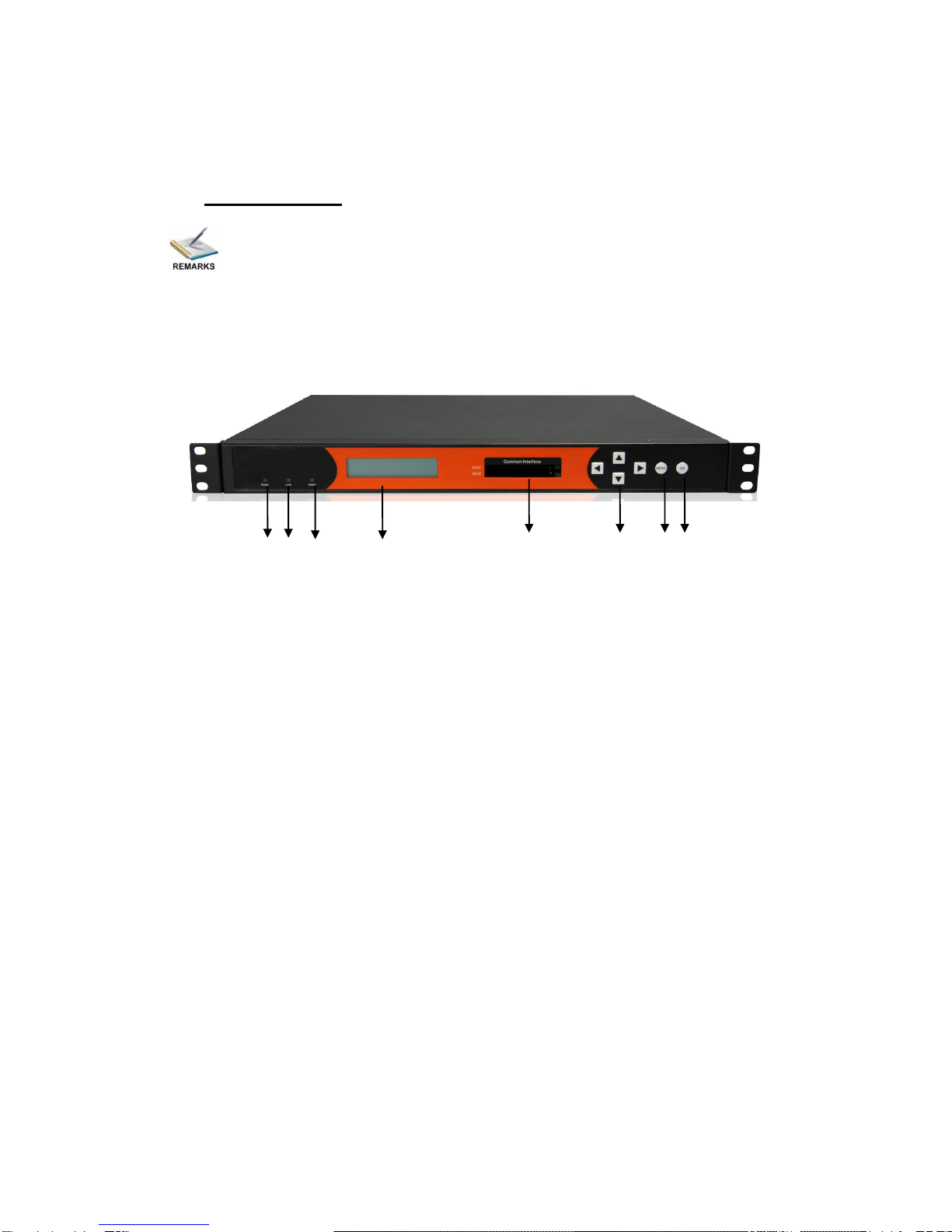
1.4.2 Operation through Front Panel Operation...................................................... 7
1.5 Technical Specifications............................................................................................ 8
1.5.1 Physical Specifications ................................................................................... 8
1.5.2 Performance and Capacity............................................................................. 8
1.5.3 Interfaces and Protocols................................................................................. 8
2Installation..................................................................................................................... 10
2.1 Installation Procedure ............................................................................................. 10
2.2 Preparation before Installation................................................................................ 10
2.3 Check Package and Accessories.............................................................................11
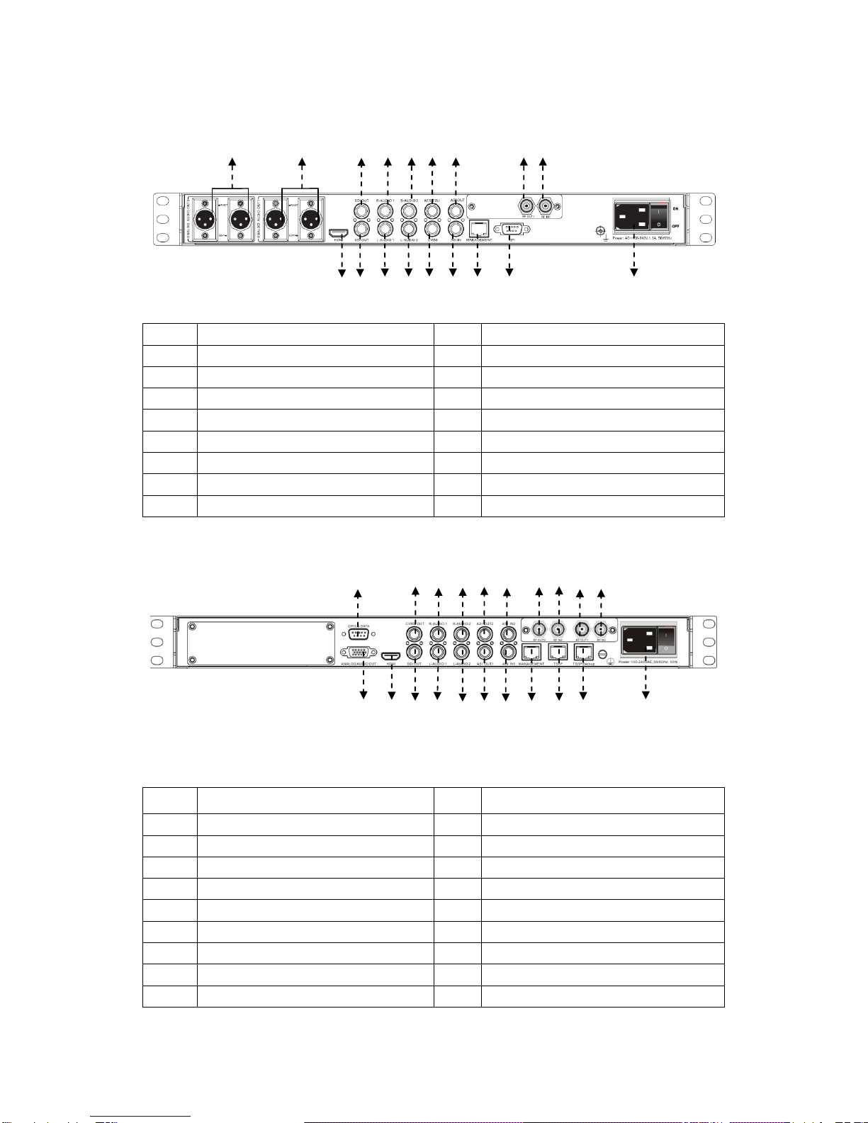
2.4 Equipment Wiring and Connection..........................................................................11
2.4.1 Connection Setup for RF Signal Input.......................................................... 12
2.4.2 Connection Setup forASI signal input.......................................................... 12
2.4.3 Connection Setup forASI signal input.......................................................... 13
3Operation Guide............................................................................................................ 14
3.1. Operation Overview................................................................................................ 14
3.2. Powering Up and Initialization................................................................................ 14
3.3. Front Panel Operation............................................................................................ 14
3.3.1 Front Panel Menu Structure.......................................................................... 15
3.3.2 Front Panel Operation Guide........................................................................ 18
3.4.WEB UI Operation (Recommended) ...................................................................... 19
3.4.1 WEB Management Connecting .................................................................... 19
3.4.2 Parameters Configuration............................................................................. 21
3.5. Operation Verification............................................................................................. 45
3.5.1 Signal Reception Verification........................................................................ 45
3.5.2 Descrambling Function Verification.............................................................. 46
3.5.3 Decoding Function Verification..................................................................... 46
3.6. Preparation before Officially Operation.................................................................. 47
3.6.1 Clear all useless data.................................................................................... 48
3.6.2 Configure the equipment with working data................................................. 48
3.6.3 Full checking before implementation............................................................ 48
4FAQ ............................................................................................................................... 49
5Terminology................................................................................................................... 51

4
1 About This Product
1.1Introduction
This product is a new generation integrated receiver decoder to support the growing
demands for multi-format, multi-standard video delivery and distribution. It can receive
digital signals from several of inputs (DVB-S/S2, DVB-C (optional), DVB-T/ISDB-T (optional)
and ASI), decrypt, and process/select programs to various outputs including CVBS, HDMI,
SD/HD SDI and ASI. It supports multi-channel descrambling, multiplexing, external
table/data insertion, transcoding and transmodulating. It also supports video decoding with
two audio channels. With remote web-based management interface, it is ideal to support
advanced application such as content distribution, real-time signal conversion and
transmission.
1.2 Safety
To avoid electric-shock hazards, do not open the receiver; refer service to qualified
personnel only.
Do not expose the device in the sunlight, and keep it away from the heat source.
Do not block ventilation holes of the device so that air can circulate freely.
Switch the device off whenever it remains out of service for an extended period.
Be sure to turn the device off and disconnect the AC power cord before cleaning the
receiver surface.
The apparatus shall be connected the mains socket outlet with a protective earthing
connection
The appliance coupler used as the disconnect device shall remain readily operable.
This product has gone through regulated EMC test and meets with EMC safety
requirement.
( Such tests are conducted in a controlled EMC environment. A controlled
EMC environment exists in a building where the installation has been designed

5
having special regards to EMC, and where technical personnel are present with
experience of EMC technology.)
1.3 Architecture
The equipment of this section is shown in schematic diagram. It is subject
to change for improvement on the real product without advanced notice.
Front Panel
12 3 4 5 6 7 8
PIC-1.3-1
1. Power status indicator: This LED light is turned on when the IRD is power on.
2. (Signal) Lock status indicator: This LED light is turned on when a channel is locked.
Otherwise there is no channel locked.
3. Alarm status indicator: This LED flickers when there is something abnormal. For
example, the strength of the input signal is too weak.
4. Display screen: This LCD screen can show the program and configuration information.
5. CI SLOTS: There are two CI slots for various CAS CAM (PCMCIA) modules.
6. KEY PADS:
Up/Down/Left/Right arrow keys: To change channels, to adjust volumes and
configure the IRD.
Menu: To enter the menu and the quit function of the sub menus.
OK: To confirm the operation in the setup.

6
Rear Panel (UMH160R-Base)
14 15 17 3 579 12 13
1 17 2 46810 11 16
PIC-1.3-2
1
HDMI Output
2
L-Audio 1
3
R-Audio 1
4
L-Audio 2
5
R-Audio 2
6
CVBS
7
AES/EBU
8
ASI Out
9
ASI IN
10
MANAGEMENT
11
GPI
12
RF IN
13
RF Out
14
Balanced L/R Analog Audio Out2
15
Balanced L/R Analog Audio Out1
16
Power switch
17
SDI Out (Optional)
Rear Panel (UMH160R-AD)
11 4 689 10 17 18 12 13
1 2 3 5 7 9 10 14 15 16 19
PIC-1.3-3
1
Analog Audio Out
2
HDMI Out
3
SDI Out
4
CVBS
5
L-AUDIO1
6
R-AUDIO1
7
L-AUDIO2
8
R-AUDIO2
9
ASI Out
10
ASI IN
11
GPI
12
RF LOOP OUT 2
13
RF IN2
14
MANAGEMENT
15
TS/IP
16
TS/IP
17
RF LOOP OUT 1
18
RF IN 1
19
Power switch

7
1.4 Methods of Operation
1.4.1 Operation through WEB UI
Operate the IRD remotely through WEB UI. The WEB UI operation supports:
Functions
Description
Related Items
Parameters
Setting
WEB UI allows users to
conduct operations of
parameters
configuration,
modification and setup.
Signal receive setup
CI setup
Decoder setup
Status
Monitoring
Support real-time
monitoring on running
status of input signal,
CI descrambling, etc.
RF signal strength indication
CI slot/CAM information
HW/SW version information
Upgrade
Support unit upgrade
through WEB UI
1.4.2 Operation through Front Panel Operation
Operation through front panel control buttons; users can configure all the parameters as the
followings:
Functions
Description
Related Items
Parameters
Setting
Allows users to
conduct operations of
parameters
configuration,
modification and setup.
Signal receive setup
CI setup
Decoder setup
Status
Monitoring
Support real-time
monitoring on running
status of input signal,
CI descrambling, etc.
RF signal strength indication
CI slot/CAM information
HW/SW version information

8
1.5 Technical Specifications
1.5.1 Physical Specifications
Items
Index
Power
AC90~260V, 50/60Hz
Max. Power Consumption
Approx 50W
Size
1RU
Dimension
484mm (L) ×274mm (W) ×44mm (H)
Net Weight
Approx 3.8Kg
Gross Weight
Approx 5Kg
1.5.2 Performance and Capacity
Items
Index
ASI Max. Input Bitrate
100Mbps
ASI Max. Output Bitrate
100Mbps
Decoder Max. Resolution
1920 X 1080i
CI Max. Output Bitrate
100Mbps
1.5.3 Interfaces and Protocols
Physical Connector Interfaces
Inputs
IP input (UMH160R-AD )
ASI input
Interface: 1 x 1000 Mbps
Interface: 2 ASI inputs, 75Ω
IP Encapsulation: UDP/RTP
MPEG Format: 188/204 Bytes per
TS
MPEG TS: MPTS and SPTS
Max bit rate: 120 Mbps (per TS)
Input processing: Up to 12
Sockets, max at 72 Mbps per
socket
DVB-S/S2 Input
QAM RF Input (optional)
Input Frequency: 950~2150 MHz
Frequency Range: 48~862 MHz
Constellation: QPSK, 8 PSK
Modulation Mode:
16/32/64/128/256 QAM

9
Outputs
IP output (UMH160R-AD )
ASI output
Interface: RJ 45
Interface: 2 ASI outputs, 75Ω
IP Encapsulation: UDP/RTP
MPEG Format: 188/204 Bytes per
TS
MPEG TS: MPTS and SPTS
Max bit rate: 120 Mbps (per TS)
Output processing: Up to 12
Sockets, max at 72 Mbps per
socket.
The physical connector design is subject to change without advanced notice
(either the connector type or specific connector location) according to user’s sepcifc
order, performance improvement, or for better user experience.

10
2 Installation
2.1 Installation Procedure
2.2 Preparation before Installation
Before installation, the installation personnel should read through and confirm the
followings:
Go through this user manual.
Has the knowledge of digital television system.
Has defined the sources, racks allocation, and set-up plan system wiring.
Knows how to operate this unit and parameters configuration.
Go through related engineering design documents about the system.
Preparation before
Installation
Check Package
and Accessories
Setup Connection
(signals, wiring)
Parameters
Configuration
System Debug
Finish

11
2.3 Check Package and Accessories
The IRD package includes the following accessories:
Base Unit x1
Power cord x1
Earth cord x1
BNC cord x1
BNC-RCA cord x2
User Guide Disc x1
2.4 Equipment Wiring and Connection
To avoid electric shock and damage to the equipment, before setting up the
wiring connection, please power off the equipment and all other connected external
devices. The equipment and external devices must be grounded. Powering on the
equipment only after all the wiring connection is completed.
Connection Diagram (For UMH 106R-base)
PIC-2.4-1

12
Connection Diagram (For UMH 106R-AD)
PIC-2.4-2
In actual application, not all connection interfaces need to be connected with
signal/external devices. Please connect according to actual application purpose.
To ensure a smooth communication between the management PC and the
IRD, please try to connect the IRD management port to a switch without large data
processing.
2.4.1 Connection Setup for RF Signal Input
Connect signal to tuner input (either RF1 or RF2 input) with a RF cable.
Connect the IRD “Management” port to a switch, set up a management network with
the management PC.
Connect the IRD with the monitor via HDMI, SDI or CVBS ports.
2.4.2 Connection Setup for ASI signal input
Connect ASI signal to IRD “ASI IN” port with a BNC cable.
Connect the IRD “Management” port to a switch, set up a management network with
the management PC.
Connect the IRD with the monitor via HDMI, SDI or CVBS ports.

13
2.4.3 Connection Setup for ASI signal input (UMH160R-AD)
Connect IP signal to IRD “TS/IP” port with a twisted cable.
Connect the IRD “Management” port to a switch, set up a management network with
the management PC.
Connect the IRD with the monitor via HDMI, SDI or CVBS ports.

14
3 Operation Guide
3.1. Operation Overview
This chapter provides information on how to operate the IRD through front panel and WEB
UI. User can select the most proper operation method to set up the unit.
3.2. Powering Up and Initialization
Before powering-up the device, make sure that all cabling is correctly
connected (refer to chapter 3.4 of this manual). The device is correctly connected to
the power inlet and grounded.
Switch on the equipment through the rear power switch, and the unit is powered up and
starts the initialization.
The LCD screen is lighted up, and display information as following:
The initialization takes about 20 seconds to complete, and then the IRD shows the IP
address information as following:
If the unit fails to initialize and hangs at the “booting”stage, swtiching off the
device and then powering up again may help. If the device still fails to initialize,
please contact your service representative for help.
3.3. Front Panel Operation
Ways of operation: use the 6 navigation keys on front panel: Up / Down / Left / Right / Menu /
UMH160R IRD
IP: 192.168.001.016
UMH160R IRD
Booting…

15
Ok to configure the IRD parameters. The configuration and settings are displayed through
front panel LCD.
3.3.1 Front Panel Menu Structure
For UMH 160R-BASE:
1st Layer
2nd Layer
3rd Layer
4th Layer
Default Settings
Inputs
Source Select
ASI
Tuner 1
Tuner 2
Receiver
ASI
Tuner 1
LNB Frequency
5150MHz
Satellite Frequency
3840MHz
Symbol Rate
27500KBaud
LNB Voltage
Off
LNB 22KHz
Off
LNB Type
C Band
Tuner 2
LNB Frequency
5150MHz
Satellite Frequency
3840MHz
Symbol Rate
27500KBaud
LNB Voltage
Off
LNB 22KHz
Off
LNB Type
C Band
Source Config
RF Auto-Switch
Disable
ASI Auto-Input
Disable
Source
Standard Set
DVB
Outputs
Program
Setup
Decoder
Program
Program Playlist
The 1st program

16
Setup
Video
Video standard
Auto
Aspect Ratio
Auto
Video Format
1080i
Audio
Audio Volume
0
Audio Mixer
Stereo
Audio1 Language
Audio2 Language
Subtitle
Subtitle Standard
EBU
Subtitle Language
EBU
System
Local Setup
DHCP Enable
On
Local IP Address
192.168.0.16
Local Network Mask
255.255.255.0
Local Gateway
192.168.1.1
Trap IP Address
000.000.000.000
MAC Address
HW Version
Properties
SW Version
FW version
Factory
Setting
NO
Alarm Setting
Off
Status
Input status
ASI
ASI Status
TS Rate
Tuner 1
Tuner 1 Status
FEC Rate
BER
Frequency Offset
Frequency Tune

17
RF Level
C/N
TS Rate
Tuner 2
Tuner 1 Status
FEC Rate
BER
Frequency Offset
Frequency Tune
RF Level
C/N
TS Rate
Output
Status
Program No.
1st program
information in
program list
PCR PID
Audio PID
Video PID
PMT PID
CI Status
CI Slot1
EMPTY
CI Slot2
EMPTY
CA
Common
Interface
CIMultiDecryntMode
MultiPMT
CAM MAX Bittraate
72Mbps
Biss Setting
Biss Mode
Biss-1 Mode
Biss-1 Setup
Biss Key
Biss-E Setup
Biss-E Id
Biss-E Key
DTMF
1
Front Panel Menu Structure (For UMH 160R-AD)
1st Layer
2nd Layer
Default Settings

18
Ethernet
Host IP Address
192.168.1.98
Host Subnet Mask
255.255.255.0
Host Gateway
192.168.1.1
Host MAC Address
Trap IP Address1
000.000.000.000
Trap IP Address1
000.000.000.000
System
Language
English
Factory Setting
No
Power Alarm
Clear Power Alarm
Eth Control
Reset Eth
Version
Software version
Hardware version
3.3.2 Front Panel Operation Guide
Enter “Menu”:
oPress “MENU” button to enter main menu.
Exit Menu/Back to parent Menu
oUpon completion of configuration settings, press “MENU” button until you
go back to the Parent Menu.
Enter Sub-Menu
oPress MENU button to enter main menu.
oSelect a sub-menu by pressing arrow UP and arrow DOWN button.
oPress OK button on the selected sub-menu.
To change parameter
oStep 1: Enter main menu by pressing MENU button.
oStep 2: Scroll sub-menu by pressing arrow UP and arrow DOWN button,
and press OK button to change the selected sub-menu.
oStep 3: To change parameter settings, press arrow RIGHT and arrow LEFT
button to move the cursor in which change must be made.

19
oPress arrow UP button and arrow DOWN to input / select an appropriate
setting, then press OK button to save.
3.4. WEB UI Operation (Recommended)
Accessing the equipment via Web can be very convenient for remote configuration of the
equipment. Relative to the front panel settings WEB operation can provide a more friendly
man-machine interface, and with less limits in space. WEB Management is recommended.
3.4.1 WEB Management Connecting
Connection Instruction for UMH 160R-Base:
PIC-3.4-1
Connection Instruction for UMH 160R-AD:
PIC-3.4-2
1. Connect the “MANAGEMENT” port of the IRD to a network switch and connect the
management PC/server to the same network switch.
Other manuals for UMH160R
1
Table of contents