Wells WVU96 User manual

WELLS BLOOMFIELD, LLC
265 Hobson St. • Smithville, TN 37166
telephone: (800) 264-7827
wells-mfg.com
IMPORTANT: DO NOT DISCARD THIS MANUAL
This manual is considered to be part of the appliance and is to be given to the OWNER or
MANAGER of the restaurant, or to the person responsible for TRAINING OPERATORS of
this appliance. Additional manuals are available from your WELLS DEALER.
THIS MANUAL MUST BE READ AND UNDERSTOOD BY ALL PERSONS USING OR
INSTALLING THIS APPLIANCE. Contact your WELLS DEALER if you have any
questions concerning installation, operation or maintenance of this equipment.
OWNERS MANUAL
VENTLESS UNIVERSAL
HOOD SYSTEM
for
ELECTRIC
COOKING
APPLIANCES
MODEL
WVU96
Manual Includes
INSTALLATION
USE & CARE
EXPLODED VIEW
PARTS LIST
WIRING DIAGRAM
522-2
2M-Z23216 REV C (08-22)
Model WVU-96

LIMITED EQUIPMENT WARRANTY
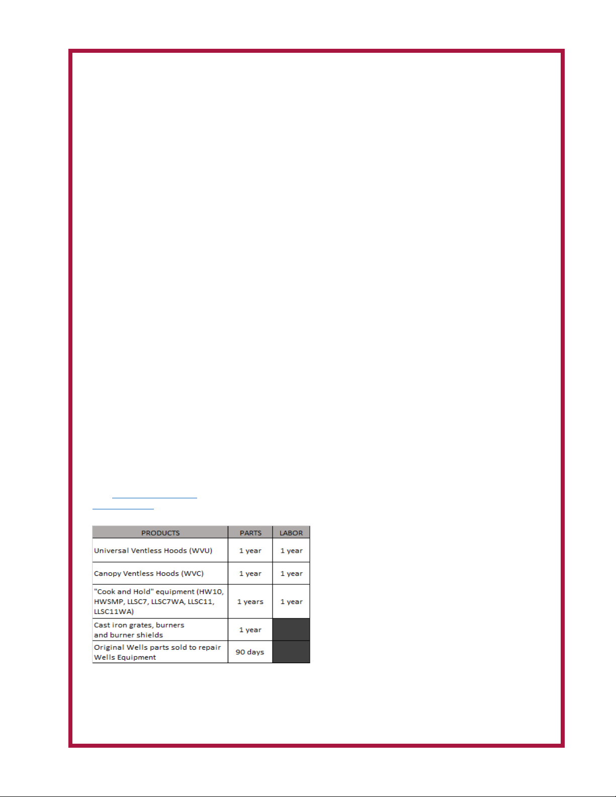
Wells Manufacturing warrants to the original purchaser of new Wells
products to be free from defects in material or workmanship, under normal
and proper use and maintenance service as specified by Wells and upon
proper installation and start-up in accordance with the instructions
supplied with each Wells unit. Wells’ obligation under this warranty is
limited to a period of one [1] year from the date of original installation, or
eighteen [18] months from original invoice date, whichever occurs first.
Defects that occur as a result of normal use, within the time period and
limitations defined in this warranty, will at Wells’ discretion have the parts
replaced or repaired by Wells or a Wells-authorized service agency.
THIS WARRANTY IS SUBJECT TO ALL LISTED CONDITIONS
Repairs performed under this warranty are to be performed by a Wells
authorized service agency. Wells will not be responsible for charges
incurred or service performed by non-authorized repair agencies. In all
cases, the nearest Wells-authorized service agency must be used. Wells will
be responsible for normal labor charges incurred in the repair or
replacement of a warrantied product within 50 miles (80.5 km) of an
authorized service agency. Time and expense charges for anything beyond
that distance will be the responsibility of the owner. All labor will need to
be performed during regular service hours. Any overtime premium will be
charged to the owner. For all shipments outside the U.S.A. and Canada,
please see the International Warranty for specific details. It is the
responsibility of the owner to inspect and report any shipping damage
claims, hidden or otherwise, promptly following delivery. No mileage or
travel charges will be honored on any equipment that is deemed portable.
In general, equipment with a cord and plug weighing less than 50 lb. (22.7
kg) is considered portable and should be taken or shipped to the closest
authorized service agency, transportation prepaid.
CONTACT
Should you require any assistance regarding the operation or maintenance
of any Wells Manufacturing; phone or email our service department. In all
correspondence provide the model number and serial number of the unit
needing service; include the voltage or gas type.
Normal Business Hours: 8:00 a.m. to 4:30 p.m. Central
Telephone: 800-264-7827 Tech Service Option 2
Email: TechService@partstown.com
www.Wells-Mfg.com
WARRANTY EXCLUSIONS
THE FOLLOWING WILL NOT BE COVERED UNDER WARRANTY.
Wells’ sole obligation under this warranty is limited to either repair or
replacement parts, subject to the additional limitations detailed
below. This warranty neither assumes nor authorizes any person to
assume obligations other than those expressly covered by this
warranty.
• Any product which has not been used, maintained, or installed in
accordance with the directions published in the appropriate
installation sheet and/or owner’s manual, including incorrect gas or
electrical connection. Wells is not liable for any unit which has been
mishandled, abused, misapplied, subjected to harsh chemicals,
modified by unauthorized personnel, damaged by flood, fire, or other
acts of nature [or God], or which have an altered or missing serial
number.
• Installation, labor, and job checkouts, calibration of heat controls,
air and gas burner/bypass/pilot adjustments, gas or electrical system
checks, voltage and phase conversions, cleaning of equipment, or
seasoning of griddle surface.
• Replacement of fuses or resetting of circuit breakers, safety
controls, or reset buttons.
• Replacement of broken or damaged glass components, quartz
heating elements, and light bulbs.
• Labor charges for all removable and consumable parts in gas
charbroilers and hotplates, including but not limited to burners,
grates, and radiants.
• Any labor charges incurred by delays, waiting time, or operating
restrictions that hinder a service technician’s ability to perform
service.
• Replacement of parts that fail or are damaged due to normal wear
or labor for replacement of parts that can be replaced during a daily
cleaning routine, such as but not limited to silicone belts, PTFE non-
stick sheets, control labels, knobs, bulbs, fuses, quartz heating
elements, baskets, racks, and grease drawers.
• Any economic loss of business or profits.
• Non-OEM parts. Use of non-OEM parts without Wells’ approval will
void the warranty.
• Units exceeding one [1] year from original installation date, or more
than eighteen [18] months from original invoice date, whichever
comes first.
ADDITIONAL WARRANTIES
• Specific/chain-specific equipment may have additional and/or
extended warranties.
The foregoing warranty is in lieu of any and all other warran�es
expressed or implied and cons�tutes the en�re warranty.
xi

M522 p/n 2M-Z23216 OpM WVU- Universal Hood
1
Thank You for purchasing this Wells Manufacturing appliance.
Proper installation, professional operation and consistent maintenance of this appliance will ensure
that it gives you the very best performance and a long, economical service life.
This manual contains information and instructions for the ventless ventilation hood, its use and care.
For information regarding cooking appliance(s), please refer to the manufacturer’s operation manual.
Note: Wells Ventless does not qualify for free prepaid freight. Wells Ventless is made to order and is
non-refundable.
TABLE OF CONTENTS
ELECTRICAL SPECIFICATIONS
INTRODUCTION
Model Volts Amps Power Supply
WVU96 208/240V 8.0 For supply connection use #12 AWG copper wire only.
WARRANTY xi
ELECTRICAL SPECIFICATIONS 1
FEATURES & OPERATING CONTROLS 2-3
PRECAUTIONS & GENERAL INFORMATION 4
INSTALLATION 5
Unpacking & Inspection 5
Components 5
Under-Hood Appliance Limitations 6-7
Service Technician Installation Notes 8-9
Base Assembly 10-11
Electrical Installation 12-13
ANSUL® INSTALLATION & SETUP 14-15
Filter Installation 16
OPERATION 17
Operation Lights 17
CLEANING INSTRUCTIONS 18-19
DISCHARGE DIRECTION CHANGE 20
REQUIRED MAINTENANCE & MAINTENANCE LOGS 21-25
TROUBLESHOOTING SUGGESTIONS 26
WIRING DIAGRAM 27
EXPLODED VIEW & PARTS LIST 28-37
PARTS & SERVICE 38
CUSTOMER SERVICE DATA 38
APPLICATION FOR VENTLESS APPROVALS 39-40

2
M522 p/n 2M-Z23216 OpM WVU- Universal Hood
FEATURES & OPERATING CONTROLS
IL2391a
12 11
13
14
20
19
15
24
10
9
43 5 6
7
8
16
17
2
22
23
21
1
18
Ventilator Section Operating Features & Controls

M522 p/n 2M-Z23216 OpM WVU- Universal Hood
3
FEATURES & OPERATING CONTROLS continued
FEATURES & OPERATION CONTROLS
ITEM
NO DESCRIPTION COMMENT
1VENTILATOR EXHAUST DUCT,
TOP Exit point for ventilator airow - on top of unit. DO NOT BLOCK
2VENTILATOR EXHAUST DUCT,
FRONT
Exit point for ventilator airow - on front of unit. DO NOT
BLOCK
3 VENTILATOR FAN Provides air movement for ventilation
4HI-EFFICIENCY/CHARCOAL
FILTER PACK
Removes grease and smoke particles. Also assists in cooking
odor removal.
5 NAMEPLATE Gives manufacturer, make and model description. Also list
voltage and amperage data.
6FIRE SUPPRESSION TANK Container for ANSUL® Low-pH Liquid re suppression uid.
7ACTUATOR ASSY Triggers deployment of suppression uid through manual pull
station or electric detection.
8 ANSUL® CARTRIDGE Propels suppression liquid through suppression manifold and
nozzles.
9 MANUAL PULL STATION Provides a means of manual activation of the re suppression
system. PULL ONLY IN CASE OF FIRE!
10 ADJUSTABLE LEGS Allows the unit to be leveled.
11 AIR WALL A wall of air that moves the grease and smoke particles into the
lter system.
12 DISCHARGE NOZZLES Fire suppression media discharges here, (6 places 48”, 12
places 96”)
13 ELECTRICAL DETECTORS
Designed to activate at certain temperature. Activates (i.e. re
on the cooktop) activates re suppression system. Should be
checked every 6 months during ANSUL® Service Inspection
14 APPLIANCE LIGHT ON when hood power switch is ON. Illuminates cooking area.
15 GREASE DRIP TRAY Collects grease/moisture dripping from bae lter (16)
16 BAFFLE FILTER Extracts and drains most greases and moisture from the air
ow.
17 PRE-FILTER ASSEMBLY
Comprises the PRE-FILTER FRAME and a replaceable PRE-
FILTER. Stops large particles of grease from reaching the
FILTER PACK for reduced maintenance costs.
18 ELECTRICAL CONNECTION BOX Houses electrical components
19 GROUND LUG Ground wire of power connection connects here.
20 EQUIPMENT INTERFACE
CONTACTOR
Energizes cooking appliances only while ventilator section is
sensed as operational.
21 BUILDING FIRE ALARM RELAY Reports re alarm condition to building re management
system.
22 DETECTION END OF LINE
RELAY
Prevents appliance operation if a fault is found in detection
circuit.
23 SUPPLY CONNECTION
TERMINAL BLOCK Provides connection point for electrical circuitry
24 FILTER INTERLOCK SWITCHES Proper installation of bae lter and lter pack closes these
switches in ventilator sensor circuit
Table of contents
Other Wells Ventilation Hood manuals
Popular Ventilation Hood manuals by other brands

Gorenje
Gorenje S3 IHGC963S4X manual

KOBE
KOBE ISX2136SQB-1 Installation instructions and operation manual

U.S. Products
U.S. Products ADVANTAGE-100H Information & operating instructions

Kuppersberg
Kuppersberg DUDL 4 LX Technical Passport

Framtid
Framtid HW280 manual

Thermador
Thermador HGEW 36 FS installation manual