Wellsys WS 15000 User manual
1
WS15000 Field Guide

2
SPECIFICATIONS
Model Name WS15000
Rated Voltage AC 120 V/60 Hz
Allowable Pressure 14-100 psi (1~7kgf/cm2)
Power
Consumption MAX 4.5 A (505 W)
Weight 71.9 lbs (32.6kg)
Refrigerant/Refrigerant Weight R-134a (1.48 oz ± 0.03 oz)
Design Pressure 280 psig (19.3 bar) (High Side)
Dimensions 360 W x 550D x 450 H (mm) (14.2 W x 21.7 D x 17.7 H (in))
Place of Installation Indoor
Storage
Hot Water 1.25L (42.3oz)
Ice 6.6 lbs (3 kg) (MAX)
Climate Class N Class (32 °C ± 1 °C) (89.6 °F ± 33.8 °C)
Safety Device Overheating Protector, Water Level Detector,
Water Leakage Shut-Off Valve, Fuse
Power Cord 1.9m (6.3ft) (74.8in)
IP Class IPX1
Room Temp Maximum: 100 °F (37.7 °C), Minimum: 50 °F (10 °C)
Source Water Temp Maximum: 90 °F (32.2 °C), Minimum: 40 °F (4.5 °C)
Relative Humidity 55% at 78 °F (25.5 °C)

3
ICE LED ICE LED will be on when the ice is ready
to be served, and blink while dispensing.
ICE DISPENSE BUTTON Push the button to dispense ice.
LED UV LED LED UV LED will be on when the product
is in operation (Yellow).
FILTERED LED FILTERED LED will be on when the product
is in operation (White).
HOT WATER LED HOT WATER LED will be on when the product
is in operation (Red).
HOT WATER SELECT
BUTTON Push the button to select hot water.
AMBIENT WATER LED AMBIENT WATER LED is on when the ambient water
is selected (White).
AMBIENT WATER
SELECT BUTTON Push the button to select ambient water.
WATER LED WATER LED will be on when the product.
WATER DISPENSE BUTTON Push the button to dispense ambient/hot water.
ICE DISPENSE SPOUT Ice is dispensed from ICE DISPENSE SPOUT.
WATER DISPENSE SPOUT Water is dispensed from WATER DISPENSE SPOUT.
DISPENSE BUTTONS
LED UV
WATER
FILTERED
AMBIENT
HOT
ICE
4
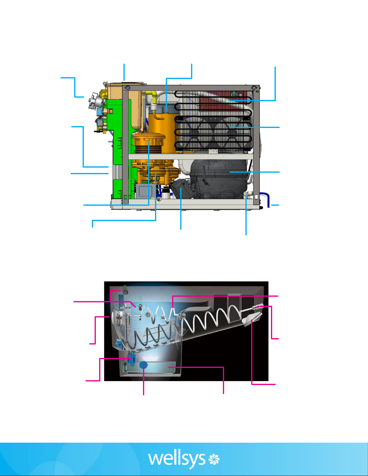
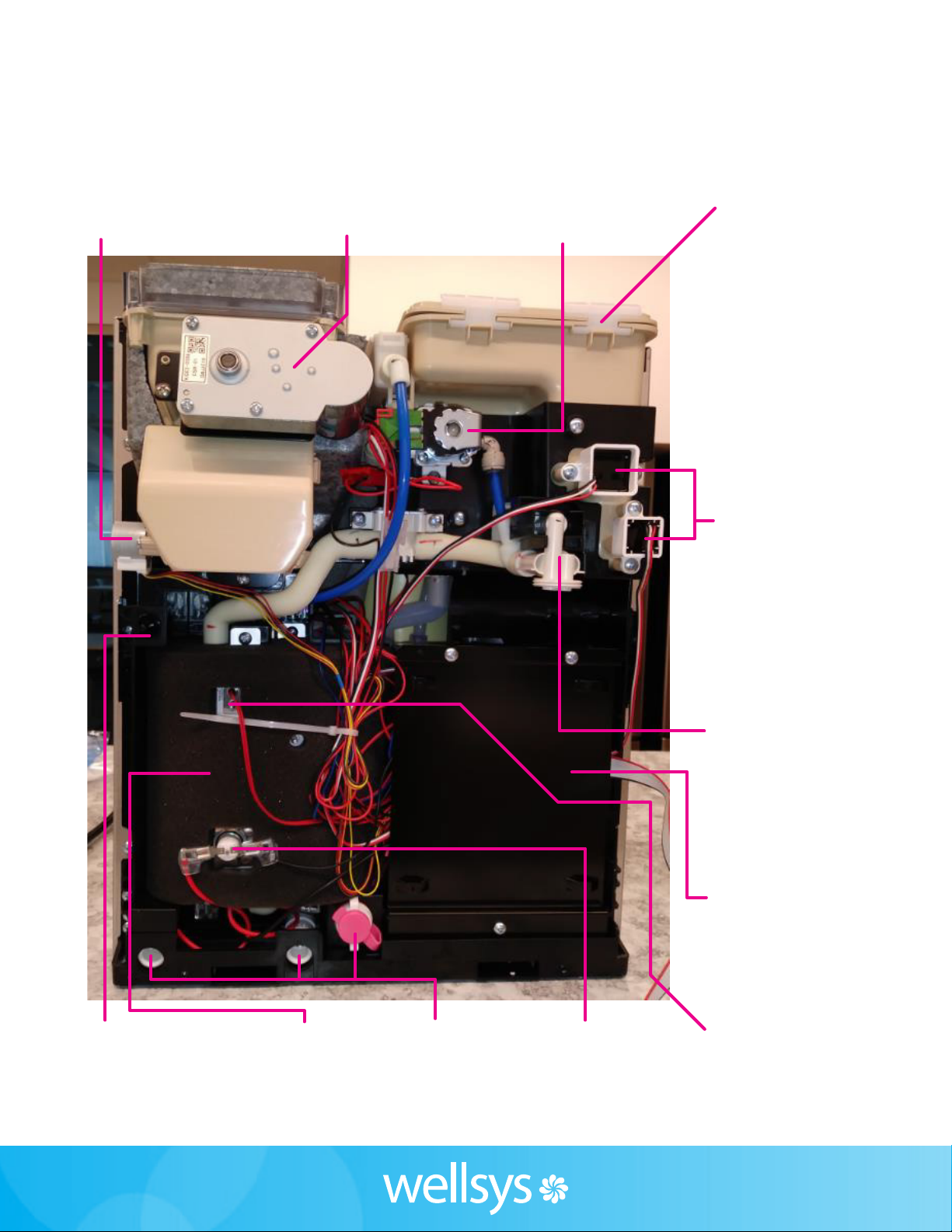
INTERIOR VIEW
RIGHT SIDE & ICE BIN
Ice Dispense
Motor
41-1911-1
Condenser
91-3616-0
Gear Motor
Transmission
Cutter Auger
Motor
Compressor Start
Components
Ice Melt
Reservoir
Leak Detector
UV Sensor
Reservoir Evaporator
Control
Board
41-2046-0
Fans
Hot Tank
91-3611-0
Compressor
21-0864-0
Gear Motor
91-3608-0
Full Bin Sensors
41-2058-0
41-2059-0
Cutter Auger
21-0848-0
Dispense
Auger
21-0867-0
Dispense
Door
91-3698-0
Level Sensor
41-1432-2
Water-In
5
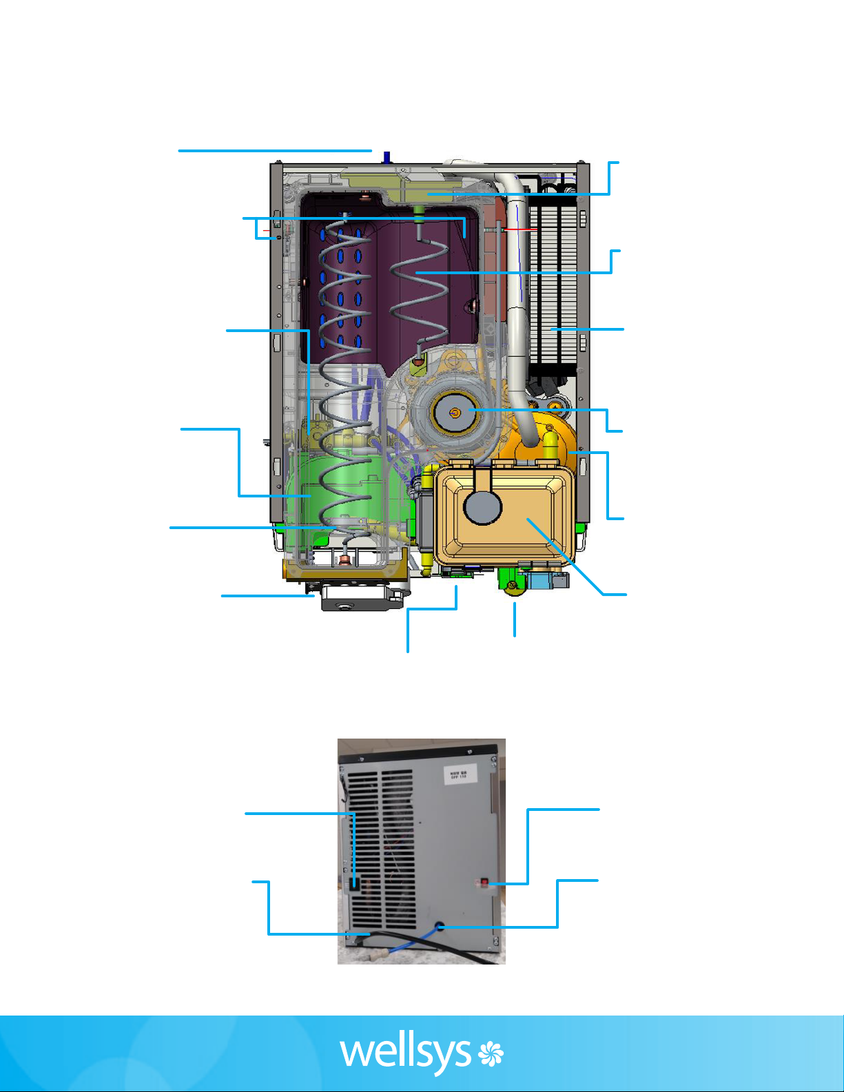
INTERIOR VIEW
TOP & BACK
Full Bin Sensors
41-2058-0
41-2059-0
Hot Solenoid
41-1768-3
Control Board
41-2046-0
Main Power
Switch
Hot Tank
Switch
Power Cord Water-In
Dispense Nozzle
91-3612-0
Gear Motor
91-3608-0
Condenser
91-3616-0
Reservoir
Evaporator
Hot Tank
91-3611-0
Cutter Auger
Motor
Cutter Auger
21-0848-0
Water-In
Dispense
Auger
21-0867-0
Ice Dispense
Motor
41-1911-1
6
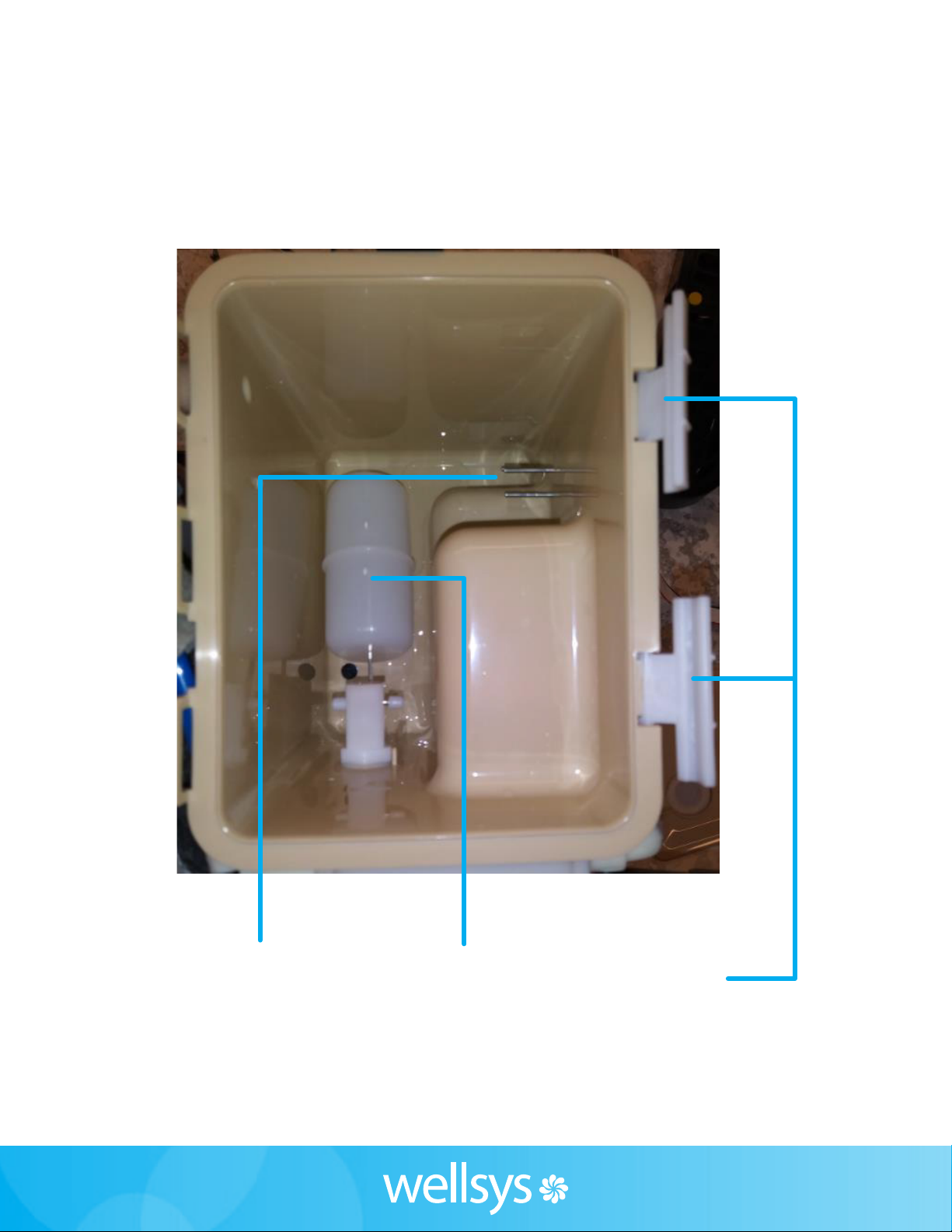
INTERIOR VIEW
WATER RESERVOIR
Level Sensor
41-1432-2
Locking
Clips
Float

7
INTERIOR VIEW
LEFT SIDE
Full Bin Sensor
41-2058-0
41-2059-0
Water-In
Leak Detector
UV Light
Hot Solenoid
41-1768-3
Level Sensor
41-1432-2
Pump
41-1405-0
Ice Dispense
Motor
41-1911-1
Damper Door
Motor
41-1285-0
8
INTERIOR VIEW
Damper
Door Motor
41-1285-0
Ice Dispense
Motor
41-1285-0
Ambient
Dispense
Solenoid
Reservoir
Hot
Dispense
Solenoid
Level
Sensor
41-1432-2
31-0577-1
Dispense
Nozzle
91-3612-0
Control
Board
41-2046-0
Hot Tank
91-3611-0
Hot Thermistor
41-0308-0
Safety
Switch
Resettable
Thermal
Cut-O
Drain
9
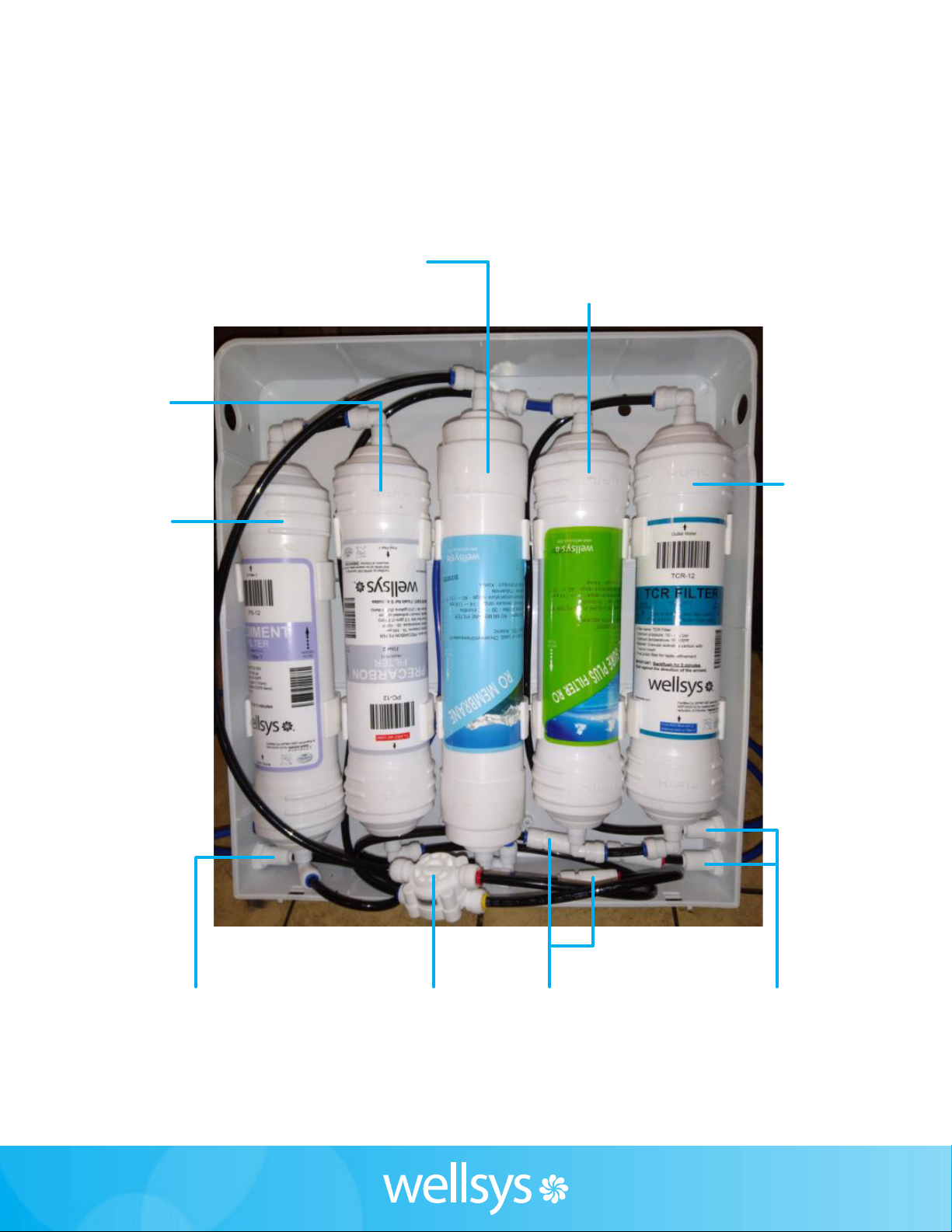
INTERIOR VIEW
FILTER ENCLOSURE
RO Membrane
HF EX3R(P)
Bulkhead
803-504-20
Bulkhead
803-504-20
ASO Valve
900-503-00
Check Valve
WSUCV
Precarbon
Filter
HF EX2(P)
Sediment
Filter
HF EX1(P)
Bio-Sure
Plus Filter
HF EX4R(P)
Post
Carbon
Filter
HF EX4R(P)
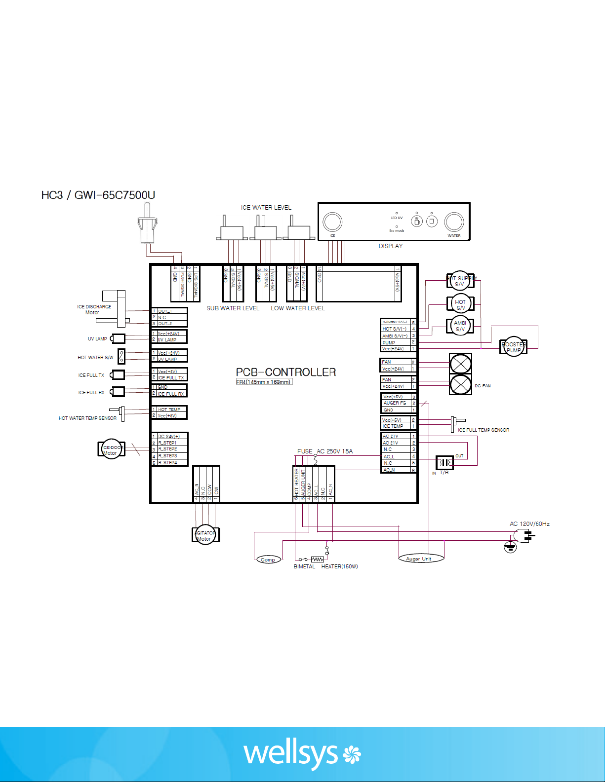
10
WIRE DIAGRAM
Other manuals for WS 15000
2
Table of contents
Other Wellsys Ice Maker manuals


