CAT-OWLG/OWLS-QSG-V1.0 EN ed. 01/2021 Welotec GmbH
Welotec GmbH
www.welotec-sensors.com
Zum Hagenbach 7
D-48366 Laer
+49 2554 9130 00
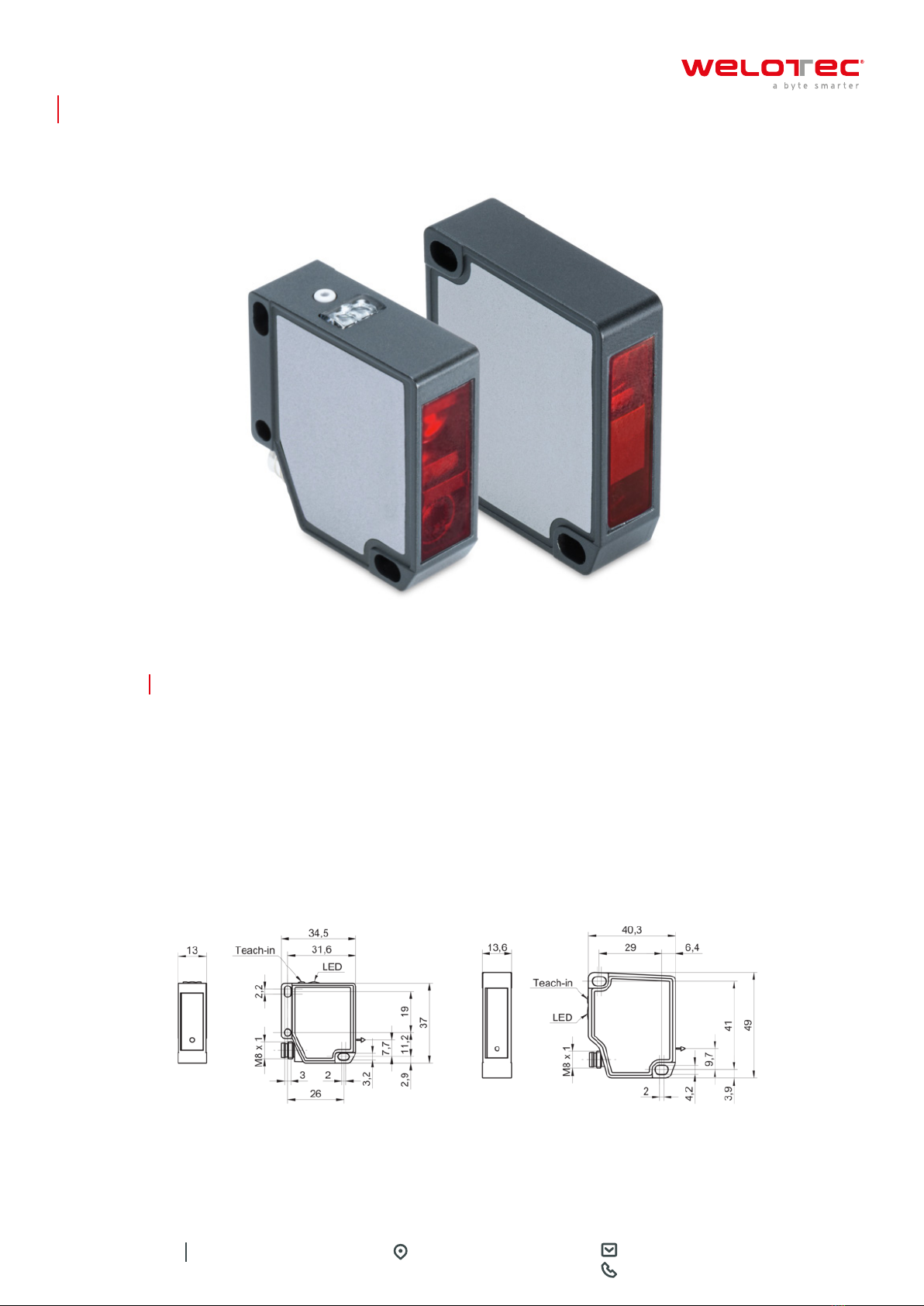
OWLG/OWLS Series
TEACHING AN ANALOG MEASUREMENT FIELD
Instruction:
a) Briefly press the Teach button.
•Red LED lights up (teach button is active).
If the red LED does not light up, restart the sensor or connect the teach-in line to +Vs for 15 seconds.
b) Press and hold the teach button for 5 seconds.
•- Red LED blinks.
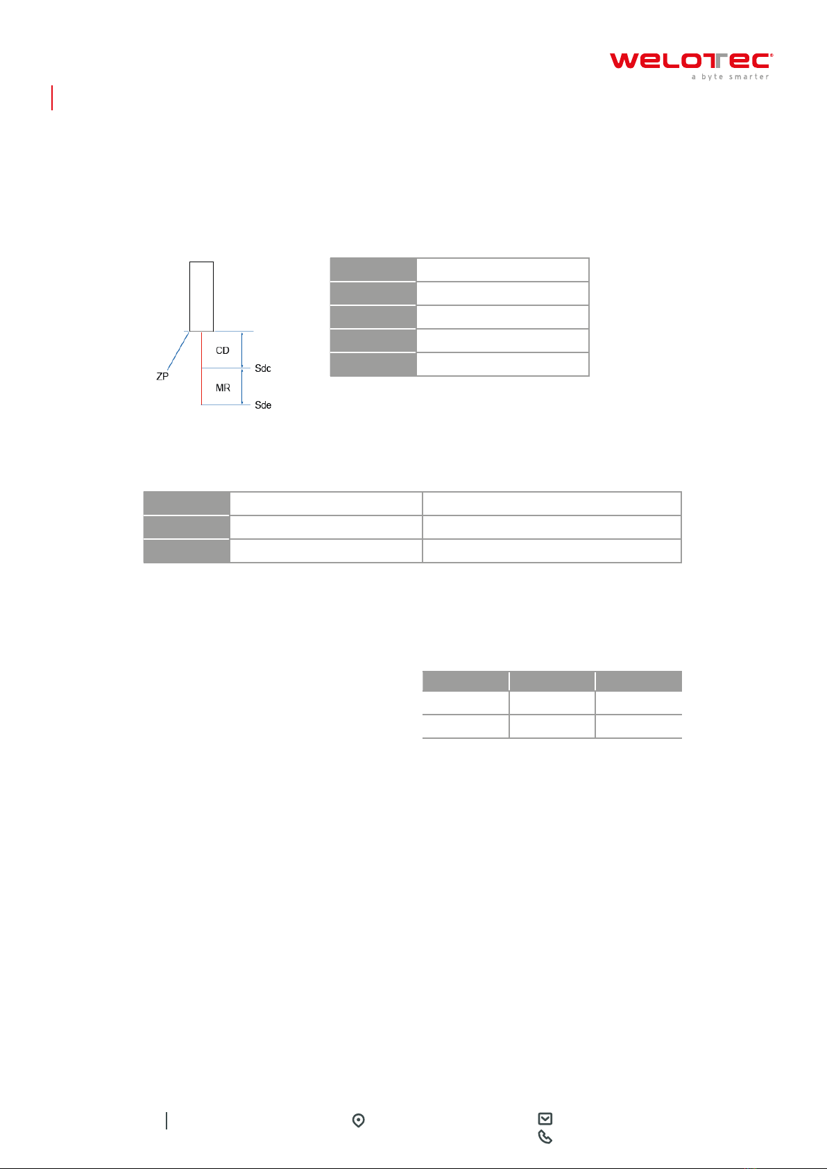
c) Teach min. limit of analog measurement range (distance at which min. voltage or min. current is displayed):
Place the measurement object on position 1 (P1) and briefly press the teach button.
•Red LED lights up for 3 seconds and then continues to blink evenly.
d) Teaching in the max. limit of the analog measurement range (distance at which max.voltage or max. current is
displayed): Place the measurement object on P2 and briefly press the teach button.
Result:
•Teach-in ok: Red LED lights up for 3 seconds and then blinks briefly. Afterwards, the sensor goes back to
operating mode.
•Teach-in not ok: Red LED blinks for 5 seconds. Afterwards, the teaching process is aborted without the
parameterization being performed.
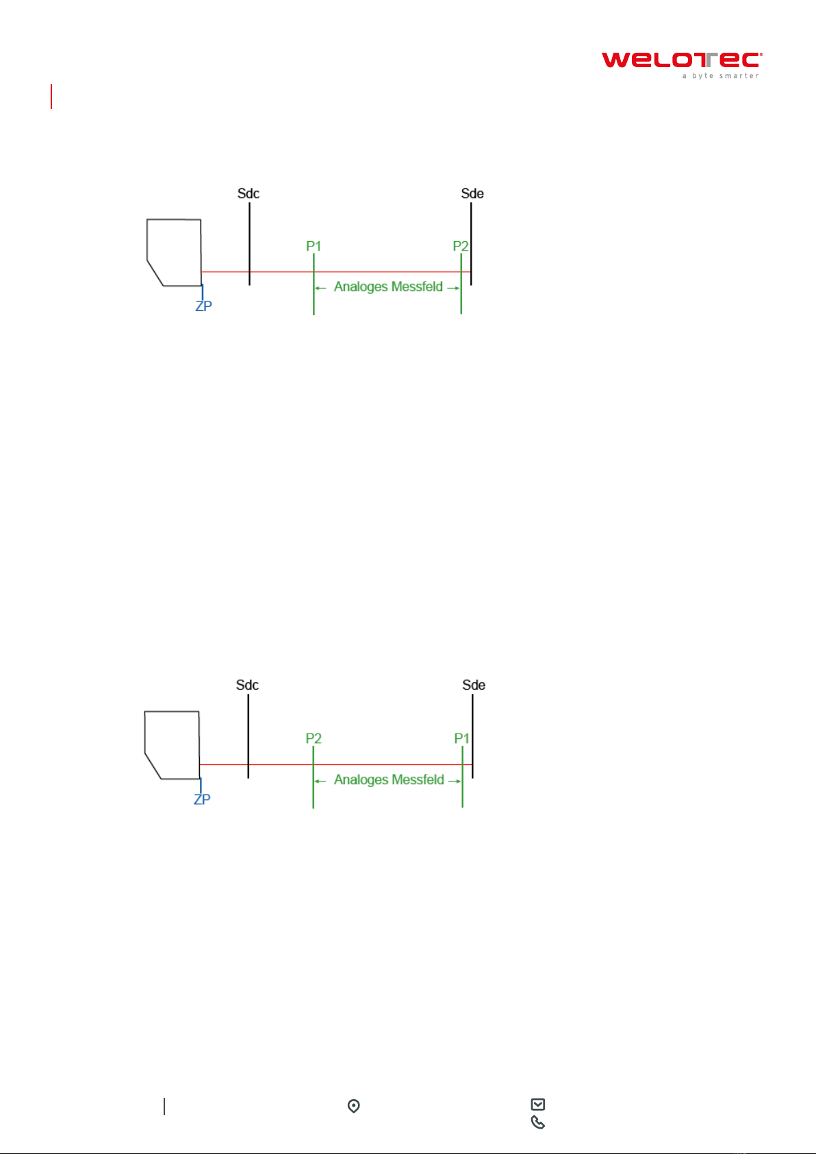
Notice:
The characteristic curve of the analog output can be inverted by the teaching process (negative gradient). To do
this, teach the maximum distance for P1 and the minimum distance for P2.
RESETTING TO FACTORY SETTINGS
Instruction:
a) Briefly press the Teach button.
•Red LED lights up (teach button is active).
If the red LED does not light up, restart the sensor or connect the teach-in line to +Vs for 15 seconds.
b) Press and hold the Teach button for 15 seconds (after 5, the red LED will start blinking, but do not release the
Teach button).
Result:
•Teach-in ok: Red LED lights up.Afterwards, the sensor goes back to operating mode.
•Teach-in not ok: Red LED blinks for 5 seconds.Afterwards,the teach process is aborted without the parame-
terization being performed.
Shifting the limits of the analog measuring field allows you to adjust the resolution of the analog output. By
narrowing the analog measuring field, smaller distance changes can be displayed.